Note: Descriptions are shown in the official language in which they were submitted.
CA 02203766 2004-09-21
77071-1
A Printer for Printing Compact Discs (CD)
The present invention relates to a printer for
imprinting individual flat substrates.
DE 43 28 011 A1 describes an apparatus that is
used for applying a plurality of coats of lacquer to sheet-
metal panels. Printing, in particular printing that
contains a register, is not foreseen for this apparatus, and
is not possible using such an apparatus. In addition, the
space between two lacquer application cylinders of two
immediately adjacent lacquer application mechanisms is
greater than the length of the sheets that are to be
lacquered.
DE 29 38 291 B2 describes a multi-ink printer used
to imprint a flat plate that is coated immediately
thereafter. The multi-ink printing is effected by the
flexographic printing method, which is a high-pressure
process. The pattern or plate cylinder is inked with a
plurality of inks next to each other and applies its ink
application onto a plate that is to be imprinted.
EP 0 581 378 A1 discloses a printer that is used
to imprint individual flat substrates, for example compact
disks (CDs) by multi-ink printing. The substrates that are
to be imprinted are delivered to a plurality of printing
mechanisms that are arranged one behind the other. The
printing points of the printers are spaced apart at a
distance that is greater that the diameters or length of the
substrates.
EP 0 518 892 B1 describes short-ink printing
machines that have no inking zones.
1
CA 02203766 2004-09-21
7771-1
It is the task of the present invention to create
a printer for multi ink imprinting of individual flat
substrates, preferably compact disks.
This task has been solved by a printer for
printing individual flat substrates, with a length or a
diameter using multi-ink printing, with a feed system for
the substrates that are to be imprinted, a plurality of
printing mechanisms that are arranged one behind the other,
as viewed in the direction of production, and whose
immediately adjacent printing points are separated by a
constant distance and an output device for the imprinted
substrates, characterized in that in each instance the
distance between two print points of two immediately
adjacent printing mechanisms is smaller than the distance or
the diameter of the substrates that are to be imprinted.
The advantages inherent in the present invention
are that the so-called planographic printing process that
uses no damping solution can be used for mufti-ink printing
in order to imprint compact disks. Starting spoilage can be
reduced because co-called short zone inking systems that
have no inking zone can be used. Several streams of
2
CA 02203766 1997-04-25
' wo 96/13386 PCT/DE95/01459
compact disks can be imprinted at the same time, although
the motives do not have to be identical. It is possible
to eliminate supporting systems along the path of
movement followed by the substrates between the printing
machines.
One embodiment isshown in the drawings appended hereto
and is described in greater detail below. The drawings
show the following:
Figure 1: a diagrammatic front view of one embodiment of
the printing machine according to the present
invention;
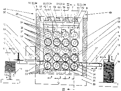
Figure 2: a cross section on the line II-1I in Figure 1.
The printer 1 is used to imprint plastic disks 2, in
particular compact disks, referred to he-reafter as disks
2. Viewed in the direction of production, this consists
essentially of a separating device 3 for the disks 2 that
are stacked, a feed apparatus that is used to move the
disks 2 that are to the imprinted from the separating
device 3 to a first printing mechanism 6, a plurality--
for example, four--of printing mechanisms 6 to 9, a
3
CA 02203766 1997-04-25
wo 96/13386 PCT/DE95/01459
conveyor system 11 to move the imprinted disks 12 to a
holding system 13 for the imprinted disks 2.
It is preferred that each of the printing mechanisms 6 to
9 be set up for printing without the use of damping
solution using so-called ultraviolet printing ink; it is
also preferred that no machine has a device to adjust the
thickness of the ink film across the inking zone.
l0 Each of the printing mechanisms 6 to 9 has a left-hand 21
and a right-hand 22 side wall; the upper and the lower
end of each of these is bolted to a frame 26 with an
upper 23 and a lower 24 cross plate. Depending on the
number of colors that is desired, the printing mechanisms
6 to 9 are arranged closely together as viewed in the
direction of production; if two-color printing is
desired, two printing mechanisms 6, 7 are arranged next
to each other, and if four-color printing is desired,
four printing mechanisms 6 are set up in this way.
A space a, for example of 100 mm, for example between the
print locations 27 to 29 and 31, is left between each two
immediately adjacent printing mechanisms 6/7 (27, 28), or
printing mechanisms 7/8 (28/29), or printing mechanisms
8/9 (29/31); according to the present invention, this
4
CA 02203766 2004-09-21
77071-1
space is smaller than the diameter, say 120 mm, of the disks
that are to be imprinted. This ensures that the disks 2 are
always securely clamped in at least one print point 27 to
29, 31 as they move through the printing mechanisms 6 to 9,
and thus cannot move uncontrolled, in such manner as to
become damaged.
Thus for all practical purposes, they move through
the printing mechanisms 6 to 9 without slipping, and are
imprinted.
As viewed in the vertical direction in which the
ink flows, each of the printing mechanisms 6 to 9 consists
of the frame 26 in which the following are accommodated: an
ink box 32 with preferably a negative doctor blade 33, an
engraved roller 34 on which the doctor blade 33 is adjusted
negatively, an ink transfer roller 36, a print forme support
roller 37 that carries a printing plate that is preferably
suitable for non-damping-solution printing, a rubber blanket
supporting roller 38 that supports a back cloth, and a
counter-pressure roller 39 that has a rubber coating.
Printing plates which can be used are manufactured and sold
for example by the company Toray under the name "waterless
Toray printing plates". When ready for printing, the
rollers 34 to 39 are all of the same diameter. However,
5
CA 02203766 1997-04-25
- wo 96/13386 PCT/DE95/01459
the raster roller 34 can be of twice the diameter or of
half the diameter of the other rollers 36 to 39.
The ink box 32 consists of a five -sided closed box and
is used to hold the ultraviolet printing ink; the
engraved roller 34 dips into this. The doctor blade 33
closes the ink box 32 offfrom below and is used to apply
the ink evenly across the whole width of the engraved
roller 34 or an appropriate partial length, insofar as a
plurality of adjacent rows of disks 2 are to be
imprinted.
The type forme is secured in the known manner, e.g., by
means of clamping rails, to the type forme carrier roller
37. The rubber blanket of_the offset blanket carrier
roller is, for example, cemented onto it.
The counter-pressure roller is arranged directly beneath
the rubber blanket carrier roller 38, and together with
this forms a print point 27, or 28, or 29, or 31, each of
which is in the form of an adjustable print gap. The
counter-pressure roller 39 can be swung away from the
rubber blanket carrier roller 58 by means of adjusting
eccentric 41, 42 in order to stop the printing operation.
The adjusting eccentrics 41, 42 are in the form of
6
CA 02203766 1997-04-25
wo 96/13386 PCT/DE95/01459
eccentric sleeves that a mounted in the left-hand 21 or
the right-hand 22 side walls so as to be simultaneously
rotatable. Left-hand 43 or right-hand 44 shaft journals
are installed in each eccentric bore of the eccentric
adjusters 41, 42 so as to be able to rotate. On the
right-hand shaft ends 44 carries in each instance a spur
pinion 46 between the counter-pressure roller 39 and the
right-hand eccentric adjuster 42 and there is another
spur pinion 47 installed on the end of the right-hand
shaft end 44 that extends beyond the side wall 22; this
is locked to the shaft.
The engraved roller 34, the ink transfer roller 36, the
type form carrier roller 37, the rubber blanket carrier
roller 38, and the counter-pressure roller 39 are each
supported in the side walls 21, 22. On their right hand
cylinder journals there is in each instance a spur-tooth
pinion 66 tQ 79 and 47 between the roller body and the
right-hand side wall 22 and this is locked to the shaft.
The pinions 66 to 69 and 47 have the same number of teeth
and form a gear train. Power is applied to this by way of
the pinion 47.
Because of the close side-by-side arrangement, and the
tight spacing between the printing mechanisms in a frame
7
CA 02203766 1997-04-25
- wo 96/13386 PCT/DE95/01459
48 it would be practically impossible to gain access to
the rollers of the printing mechanisms 6 to 9. For this
reason, it is preferred that the printing mechanisms 27
to 31 can be moved out at one side, transversely to the
direction of production, whereupon they are uncoupled
from their drives 71 and, remaining withinthe frame, can
be withdrawn until their rollers 36 to 39 are easily
accessible.
Thus, all of the printing mechanisms 6 to 9 are arranged
in a common frame 48 so as to be movable vertically
perpendicular to the direction of production, and can be
locked. The frame 48 consists of an upper front plate
49, and upper rear plate 51, a right-hand plate 52, and
left-hand plate 53, an upper plate 54, and a lower plate
56. The upper plate 54 is about half the width of the
lower plate 56. At the level of the print points 27 and
31, the right-hand plate 52 and the left-hand plate
53 each have an opening 57, or 58, respectively, that is
high enough and wide enough to pass the disks that are to
be imprinted to the first printing mechanism 6 and to
remove the imprinted disks 12 from the last printing
mechanism 9.
8
CA 02203766 1997-04-25
wo 96/13386 PCT/DE95/01459
The frame 48 is open -at the front, and the upper plate 54
covers-the lower plate to only one half its depth.
Between the front plate 49 and the rear plate 51, secured
so as to "hang" on the upper plate 54 or secured standing
on the lower plate 56, there is an upper side rod 59 or a
lower guide rod 61 for each printing mechanism 6 to 9,
and each of these is of a "keyhole" cross section. The
upper guide rod 59 is used to guide an upper front guide
piece 60 an upper rear guide piece 62. The lower guide
l0 rod 61 is used to guide a lower front guide piece 63 and
a lower rear guide piece 64. The guide pieces 62 to 64
each have two dished shells that enclose the cylindrical
part o.f the guide rods 59 or 61, respectively. The upper
guide pieces 60, 62 are secured so as to "stand" on the
cross plate 23, the lower guide pieces 63, 64 are secured
so as to "hang" on the lower side of the lower cross
plate 24. Guide rods 58, 61 and guide pieces 62 to 64
form in each instance a slide guide, with the dished
shells of the guide pieces 62 to 64 being matched to the
part of the guide rods 61, 62 with the round cross
section. In each instance, the guide rods 58, 61 and the
guide pieces 62 to 64 form a slide guide with the half
dish sections of the guide pieces 62 to 64 being matched
to the parts of the guide rods 61, 62 with the round
cross section.
9
CA 02203766 1997-04-25
wo 96/13386 PCT/DE95/01459
The displacement path of the printing mechanisms 6 to 9
is such thatthe printing mechanisms 6 to 9 can be moved
forward out of their working position so that work can be
performed on their rollers. When this is done, the pinion
47 is disengaged from a matching pinion 71, which forms
the drive for the printing mechanisms 6 to 9. The pinion
47 is half as wide as the pinion 71. The pinion 71
together with a helical-toothed pinion 72 is supported so
as to be rotatable on a first journal end 73 of a journal
74 that extends into the housing 48. The pinions 71 and
72 are connected to each other such that they cannot
turn. The journal 74 is supported in the rear plate 51
such that it cannot rotate, although it can been moved
horizontally along its longitudinal axis. A second
journal end 76 that extends out of the rear plate 51 ends
in an end casing 77 that is secured to the outside of the
rear plate 51. There is a threaded bore in a face side
78 of the casing 77 and a thread of the adjusting screw
79 fits into this. One end of the adjusting screw 79 is
connected positively and rotatably with the face side of
the journal end 75. The parts 72 to 79 are components of
a circumferential register adjusting device 81 that is
provided for each printing mechanism 6 to 9.
CA 02203766 1997-04-25
wo 96/13386 PCT/DE95/01459
A locking crank 82 that has arms of unequal length is
secured to the outside of the right-hand side wall 22,
between the roller journal ends of the ink transfer
roller 36 and the print forme carrier roller 37. The
short arm 83 of this locking crank 82 is directed upward.
A thread of an adjusting screw 84 that is used to set a
side register engages in a threaded bore in the right-
hand plate 51. One end of the adjuster screw 84 touches a
vertical face surface of the locking column 82. Just
above a face side of the short arm 83, a support crank 86
with a bearing bore is screwed onto the inside of the
right-hand plate 51. A double-arm locking crank 87 is
supported on the bearing crank 86 so it can pivot and can
be driven. One end of a first lever arm 88 of the locking
crank 87 that is fitted with a roller 85 presses the
locking crank 82 against the adjusting screw 84 when it
is in the locked state by means of the roller 85. One end
of a second lever arm 89 of the locking crank 87 is
connected to one end of a piston rod 91 of a double-
acting pneumatic cylinder 92 so as to pivot. The
pneumatic cylinder 92 rests on the right-hand plate 51.
If the piston rod 91 of the pneumatic cylinders 92 is
extended then each of the printing mechanisms 6 to 9 is
locked on the rear plate 51 by the roller $5so as to
maintain the register. If the piston rod 91 is retracted,
11
CA 02203766 1997-04-25
wo 96/13386 PCT/DE95/01459
the locking crank 87 is pivoted such that the roller 85
releases the arm 83 and thus the printing mechanism 6 to
9 that is selectively unlocked that has been released and
can be withdrawn.
The helical pinions 72 of the printing mechanisms 6 to 9
are always engaged. Power is applied to the printing
system by way of a notched belt 93 that is locked onto
the pinion 72 of the last printing mechanism 9 so as to
to be unable to rotate independently. A speed-governed D.C.
motor 94 is used as a driver and this drives a notched
disk 93 that is flanged onto the pinion 72, by means of a
drive belt. The separating device 3 can be similar to a
sheet feed for a sheet-fed rotary printing mechanism,
although much smaller. The disks 2 that have been stacked
and which are to be imprinted are fed from a prepared
stack~l4 by a suction lifter 15 that can move both
horizontally and vertically, in time with the printing
process, and are passed to the feed system 4 and then
moved to the first print point 27. Within the print
points 27 to 31 the disks 2 or 12 a gripped by the rubber
blanket carrier roller 37 and the counter-pressure roller
39 and moved by these as they are being imprinted, to the
next printing mechanism 7 to 9 or from the last printing
mechanism 9 onto a conveyor belt of the conveyor system
12
CA 02203766 1997-04-25
wo 96/13386 PCT/DE95/01459
11. While they are being moved onto the feed mechanism 4
the disks are oriented both longways and cross ways so
that they are precisely positioned and are moved into the
first print point 27 in step with the printing process,
and then moved on. From there, the disks 12, clamped into
the particular previous print point 27 to 31, move into
the next print point 28 to 31. This ensures that the
register is maintained precisely as the disks are moving
from printing mechanism to printing mechanism.
The imprinted disks 12 are lifted from the conveyor belt
or the conveyor belts of the conveyor system 11 by means
of a suction lifter 16 that is controlled in time with
the printing process, and set down onto an output stack
17 of an output stack machine 18. On their way from the
last printing mechanism 9 to the output stack 17 the
disks 12 that have been imprinted with ultraviolet
printing ink pass through the drying section of an
ultraviolet dryer 19.
13