Language selection

Search

Patent 2203822 Summary

Third-party information liability

Some of the information on this Web page has been provided by external sources. The Government of Canada is not responsible for the accuracy, reliability or currency of the information supplied by external sources. Users wishing to rely upon this information should consult directly with the source of the information. Content provided by external sources is not subject to official languages, privacy and accessibility requirements.

Claims and Abstract availability

Any discrepancies in the text and image of the Claims and Abstract are due to differing posting times. Text of the Claims and Abstract are posted:

  • At the time the application is open to public inspection;
  • At the time of issue of the patent (grant).
(12) Patent Application: (11) CA 2203822
(54) English Title: AIRBAG MODULE FOR PASSENGER SEAT
(54) French Title: SAC GONFLABLE POUR FAUTEUIL PASSAGER
Status: Deemed Abandoned and Beyond the Period of Reinstatement - Pending Response to Notice of Disregarded Communication
Bibliographic Data
(51) International Patent Classification (IPC):
  • B60R 21/207 (2006.01)
(72) Inventors :
  • BOHN, STEFAN (Germany)
  • WISSEL, WILLI (Germany)
(73) Owners :
  • TRW AUTOMOTIVE SAFETY SYSTEMS GMBH
(71) Applicants :
  • TRW AUTOMOTIVE SAFETY SYSTEMS GMBH (Germany)
(74) Agent: ROBIC AGENCE PI S.E.C./ROBIC IP AGENCY LP
(74) Associate agent:
(45) Issued:
(22) Filed Date: 1997-04-25
(41) Open to Public Inspection: 1997-10-27
Examination requested: 1997-09-25
Availability of licence: N/A
Dedicated to the Public: N/A
(25) Language of filing: English

Patent Cooperation Treaty (PCT): No

(30) Application Priority Data:
Application No. Country/Territory Date
196 16 940.2-21 (Germany) 1996-04-27

Abstracts

English Abstract


The invention concerns an airbag module for the passenger
seat in a motor vehicle. The module is characterized by a
cylindrical compressed-gas reservoir (i), a tube (2) that
encloses the reservoir (1) and has gas-outlet openings (3)
distributed along it, two lateral components (4) that are
stamped out of sheetmetal and can be forced together along
with the tube (2) by the compressed-gas reservoir (1), and an
air sack (5) that is provided with a section enclosing the
tube (2), that is secured to the tube (2) by means similar to
tensioning straps, and that is folded over the tube (2).


French Abstract

Sac gonflable pour le fauteuil passager d'un véhicule motorisé. Le sac comprend : un réservoir cylindrique à gaz comprimé (i); un tube (2), qui entoure le réservoir (1), et sur lequel sont réparties des ouvertures de sortie du gaz (3); deux éléments latéraux (4) fabriqués de tôle emboutie, et ayant la faculté d'être compressés, l'un contre l'autre avec le tube (2), par le réservoir à gaz comprimé; et un sac à air, plié au-dessus du tube (2), dont une partie entoure le tube (2), et qui y est fixé par un dispositif ressemblant à des courroies de serrage.

Claims

Note: Claims are shown in the official language in which they were submitted.

Claims
1. Airbag module for the passenger seat in a motor
vehicle, characterized by a cylindrical compressed-gas
reservoir ( 1 ), a tube ( 2 ) that encloses the reservoir ( 1 ) and
has gas-outlet openings ( 3 ) distributed along it, two lateral
components ( 4 ) that are stamped out of sheetmetal and can be
forced together along with the tube ( 2 ) by the compressed-gas
reservoir ( 1 ), and an air sack ( 5 ) that is provided with a
section enclosing the tube (2), that is secured to the tube
(2) by means similar to tensioning straps, and that is folded
over the tube ( 2 ),
2. Airbag module as in claim 1 but with the
provision that the air sack (5) is secured by being clamped
between the tube ( 2 ) and the lateral components ( 4 ).
3. Airbag module as in Claim 1 or 2, characterized
in that the lateral components ( 4 ) have round and cup-shaped
areas (14 & 15) shaped into them that allow them to fit into
the tube ( 2 ).
4. Airbag module as in Claim 3, characterized in
that the cup-shaped areas (14 & 15) are provided with cutouts
(16 & 17) for securing the compressed-gas reservoir ( 1 ).
5. Airbag module as in Claim 3, characterized in
that the lateral components ( 4 ) are provided with one or more
structures (11 & 12) that project radially out beyond the
cup-shaped areas ( 14 & 15 ) , allowing them to engage matching
- 7 -

cutouts (6 & 7) in the tube (2) and accordingly maintaining
the correct angle between the tube ( 2 ) and the lateral
components (4).
6. Airbag module as in Claim 3, characterized in
that at least one lateral component (4) is provided with a
cutout (20) or similar structure in the cup-shaped areas (14
& 15) that, in conjunction with a matching bevel ( 21 ) of
similar structure on the compressed-gas reservoir ( 1 ),
maintains the correct angle between the tube (2) and the
lateral component ( 4 ).
7. Airbag module as in one of Claims 1 through 6,
characterized in that the lateral components ( 4 ) are provided
with levels ( 8 ), bores ( 8 ) and similar structures for
securing the module in the instrument panel or interior of
the vehicle.
8. Airbag module as in Claim 7, characterized in
that the lateral components (4) are designed to secure an
auxiliary tube ( 10 ) (or an auxiliary rod) above the folded
air sack (5) and axially paralleling the tube (2), to which a
cap for the module can be secured by a rebound strap or
similar structure.
9. Airbag module as in one of Claims 1 through 8,
characterized in that it is enclosed in a protective cover
(13).
- 8 -

Description

Note: Descriptions are shown in the official language in which they were submitted.


CA 02203822 l997-04-2~
AIRBAG MODUr,~. FOr~ ~A-q,g~lf'~ SEAT
2 ~h~ pre~ent ill~ellti~n c~licerns an airbal~ module ~or
~i the p~qsQn~r se~t in a mc~t~1- v~hi.c]e.
4 AiT bag n~o~ulr~ for passetl~er s~at~ i.n motor
v~hicle~ a~e illr~r~sirlgly bein~ off~red for sal~ ~5 options
6 and even as oriyinal egUiplr,Q~ y ~he aU~:O!IlOtiVe illdu.~try.
7 Con~iderable effo,~ts are on tlle ot~er hand l~eing mad~ to
8 ratir~n~1;7~ Lhe manuLacture o~ ord~r t~ remain
9 intQrn.qtionAlly comp~at;iLive. Thi6 meall~ tha~ aaaes~or~
p~qcpn~r-seat airbags mu~t be providHd ~s cheaply as
11 pos,si~le.
12 The ~e~ult i~ thilt an assembly oL th~
13 afo~eT~elltion~d genufi must be ~esigne.d a~ ideal~y as po~ble
14 from t~le aspects o~ m~t~.rials, manufacture, and inqtallation.
This objec~ i5 attaill~d in accordanc~ with tl~e
16 present inverltion by an ~i~4~g modul~ o~ the a~oresaid genus
lî characl:erized by a cylindrical aon~lpressed-gas reqe~voir, a
18 tube that enclosQs t~le re~ervoir an~ ~la~ outlet openings
19 di~tribute~ along it, twu lateral c~ n~ ~s of ~I~ae~
that ca~l be ~r~n~inrl~d alon~ with ~he tube by the compressed-
~1 gas ~servoir, and an air ~ack ~lith a sectiOTI that enalose~
22 ~he tuber is ~ecured to the tube by me~ns similar to
23 t~n~i~ninq straps, and tha~ is ~olded ov~r tlbe tube.
24 The present inven~ion deIi~es from the reali~tion
~5 that such moahl~9 do not r~quire a comple~ely clos~d ho~sing

CA 02203822 l997-04-2~
and tha~ th~ compre~sed-ga~ rescrvoi~ el~ can parti.cip~te
2 to a Illore (~onsi~r~hlA~ ~ax~en~ than has previcu~iy be~n
3 supposed in provislir~g a p~q~P~J~r-side airbag with
4 A; ~ n~l 9~.a~ility.
S A~.l that is neeaded ta in~tall dnd ~urQ th~ ~ioldtld
air ~ack are a ~ub~ to enalose tl1e compr~ss~d-ga~ r~servoir
7 and t~O later~ nent R that c~n be t~nc~r~l together
8 alonq witll the re~ervoir into a ~in~le as~emPly, ~uch an
9 as~embly will lleed no lonyitudinal wall~ because the fol~ed
air saak is its~Alf ~ ql ly ~t~ble ellough. Irhe air 3ack
11 can ~ protsCt~d by a aov~ while being ~hipped a~
1~ irl~talled. such a cov~r, ho~ev~r, is by no mean~ a~w~ys
13 n~ e~ss~ry and r~present~ ollly ~ practical a~vanced ve~sion of
14 t~le pre~el1t inverltioll.
1~ ~side ~rola the compres~ed-gas res~rvoir and the air
1~ sa~k ~cc~rdin~ly, only t~le tube and the ~,wo lateral ~ -r-.nL
17 a~e ~ s~ry, and th~ ~e~ervoir .,~n be sim~ltalleously
18 exploited as a mean:3 of appl~irl~ ten~ion.
l9 ~he ldteral ~nAn~ can be ~imple punched and
20 stamped she~t:r,letal ~ctions that are easy to ~dap~ ~o arly
~l desired requirement. It CUIl ~r e:~ample be o~ a~va~ltage ~or
22 the late~al ~ s to h~ve rc: und and cup-~haped areas
23 shaped inta them that all~w t~l~3m to fit into the tube. ~he
24 ba~es of the tube ~c~ordin~ly aon~titut~, in conjunction with
area~ or the q~ - ~ r ~al that ~xtend out of thl:3 cup--~h~ped

CA 02203822 1997-04-2~
area~ and in~o the r~lan~ of orlgin, a seau~e alld
2 dimen~ionally ~tqble a~ociaLion l~etween t}l~ tu~ d the
3 lateral . -~nt~. It will also be practical tor the
4 cGmpress~d-~a3 re~s~voir, the tube, and the. lateral
S ~ s to ~e providQd witll Illements thA~ u~e an~ularly
6 precise .9~ so ~chat a ~ nn:llly ~kabl~a a~semL~ly can
7 ~e produced Witll only ~he ~n~i~n;T~g ~arl~, which ;n~ ,c
the comE~reYsed-~Jas reservoir.
g Advi~nt~ou~ 'icat~nq a1ld ~ iT'~ oL the
present inv~ntion ~r~ rq~ited in the subsidiary cl3ims, 2
11 througb 9. one ~ o~ tn~ p~s~nt in~r~tl~n will n~w
12 be ~rP~ d with r-3fer~llc4 ~ th~ ~-n~in~ drawing,
1 3 wherein
14 Pigure 1 i~ ~ peL~yl~(;Live view o~ a compress~d-ga3
re3erv0ir,
16 Figure ~. illustr~t~ an associated ~a~-dl3tributing
17 tube,
18 Figure 3 il~ trates two lateral co~lpollents
tt~cheq togeth~r ~y an .~ ry tube,
Figure 4 illustr~t~Q ail a~sembl~ ~ompo~ed ol the
21 ~~ Y illustra~ced in Fi~ur~s 1 through ~, and
22 Figur~ s ~B a xec~tion tllrough an air~ag modulc
23 without ~ ~, 7 ~7-gas reseIvoir.
2~L ~he comp~ssse~-gAs ~e~e~roir ~ illu~tratecl in
~5 P~igure 1 h~ a tl1rsaded conn c~or 22 at the top and a

CA 02203822 1997-04-2~
pr~jççtiny flF~Ilge 23 at ~:h~ hottom. Fl~llye ~3 ha~ a naL~o~r
2 bevel ~1 th~t engag~s a ~utout 20 in a lateral ~ L 4
3 (Fig. 3), r~;nt-;linin~ the corre~t anglQ ~twe~n ~ s~d-
4 gas re~ervoir 1 anu the lat~aJ I .qnt~
Figur~ 2 i] lustrates a tube 2 that hOl ' 2
6 ~t~mpr~;s~d-~a~ reservoir 1. DiF3tributed along tube 2 are
7 outl~3t ar~ninfJC 3 f~r the gas ~hat i~ suddenly r~ l when
8 the air sack i~ ~tuated, slightly con~trictill~ th~ flow oL
9 ~a~ and evenly distrl~uting it to the air ~ack ov~ the tntal
cro~s-~ction of it~ intake. ~ube 2 ha~ a ClltOUt 6 and 7 at
11 each end. Cutouts G an~ 7 operate in ~onjunction with
12 radially out~ard projecting structures 11 and 12 in th~ cup-
13 ~haped areas 1~ and 15 of lateral ,:: n, .~ 4 (E~ig. 3~ and
1~ maintain th~ L~ at the aorre~ angle to tube 1.
~i~ure 3 illustrat:e~ two lateral l?~ts 4 that
16 have been produced in all approp~iat~ shape by s~ampin~ and
17 rlln~l~;n~ them ont of xheetmetal. C~ t~ d axe fastene~
18 together by an auxiliary ~ube 10 ~or auxiliar~ rod). ~ound
19 and cup-~haped areas 14 and 15 that: ~xtend inw~rd, toward the
;" ~ nq tub, Lllat i~ nav~ be~n IJt~.du~:_d by cutting and
21 shaping. Cup-3haped area~ 14 and 15 al~low lat~r~
22 4 to fit radially tight into t~be 1. Cup-sh~ped areas 1~ and
23 15 are also provid~d witn radially outward proj~ating
24 ~tructur~s 11 and 12 that all~w lateral ~ t~ ~ I.o
2~ engilge autout 6 ~d 7 at the ~ o~ tU~R I (eig. 2) ar~d

CA 02203822 l997-04-2~
~laintain the~ t th~ ~or~ct an~le to each otl~er . Al so
2 provided in lateral c~ ~ . ~s 4 ar~ cutouts 16 an~l 17. l'h~
3 diameter of eac~ ~ut~ut 16 and 17 matches that o:~ co~pre~sed-
4 gas res~:rvoi7~ 1 or it8 tllreacled colms~Lor ~ he
purpos~ o~ cutout Z0 isr a~ has b~en her~into~oJe ~l~e~ifi-ad,
6 to maint~in, in conjun~ti4n with the narrow bev~l 21 ~n the
7 ~lange 22 on aompress~d-gas reservoir 1 ~Fig. 1~, the correcc
B angle betw2en t~le ~e~ervoir an~ ]ateral C. ~llu~ lLs 4,
9 The~e are d ~iO ~tl~er })ev~a].~ ~ qnd bores g jrl
lat~ral c ~ ~ 4 for sQcuring ~,he airba~ modllle in the
li v~hicle. ~ur~hermore, lateral ~ - ~ 4 hqve exten~lolls 18
1~ ~nd 19 for s~ in~ an ~ ry tube 10. 7~ ry tube 10
13 is need~ for attachlng arl (ullill~qtrat~d) airbag~ d~lle cap
lOs and optionally ~or auglDenting the. ~?rl~:ion exerted on the
c~ by compressed-ga~3 re3ervoir l.
16 ~i~ure 4 illu~trate~ th* ,.~:~nt~ illu~t~ted in
17 FigurQ.s 1 through 3 a~s~ .ed ~ut wl.th no nut Oll threaded
18 connector 22 . ~h~ illustr~tion is ~ n~ih l C~ in i.tself
19 and will not be tliscuss~d herein.
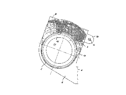
Figur~ 5, ~inal.ly, i~ a tran~ver~e s~3ction throu~h
21 the a~se~rbly illustra~ed in ~igul~ 4 without a~n~ essed-ga~
22 re~ervo~ 1 bu~ ~'7ith a $olded ~ir ~ac~c 5 qnd a protect~ve
23 cover 1-~. The l~t1:er ~Jill n~t b~ ne~ess~ry il ~olded ~ir sack
24 5 is inheren~ly ~ qinn~l ly sta~le enough. ~llch ~tability
ZS oan e~ily lle ellgureù :~y ~ nting th~ t va~iwla goiut~

CA 02203822 l997-04-2
. 1 that ~ill not pre~Terl~ it ~3:0ll~ unfol:lin~ in an . ~J~ y~
2 ~vi~lent .Ln tlle ovel-head vie.w al-e on~3 la1;eral ~c ~ Pnt ~ with
3 an e~tensioll la ~o~ ~et:uring an ~llsili~ry i:ube 10 (or
4 auxiliary rod ~ ~or att:aahin~ a pi~-oting lid . Also ~videllt are
a cup-~hap~ are~ 15 ~ a cutout 17 and }~evels B, wb.~are~y
6 th~ diam~ter of ~Jt:out 17 ecluals th~t o4 th~ nillu~trat~3
7 compr~ss~d-gas re~ervoir l.
~h~ airbay in aacorda~ae with the p~e~ent il venti~
9 has fe~ and ~a~ily prod~aed ,- - n, ~ Lq. It can be co~t-~
eff~ctively mallu:~actured ~lld is easy t~ 3taLl, w~ler~l~y
11 bevels ~ and bores 9 c~n easily be adap~:ed to various
12 ins~all3nent ~ituations~. Compress~d-~a~ ~2~3ervvi~
13 exploited as a te~l~iol~ing deviae foL attachi!lg lat~r~l
n, q 4 ~o tube 2. Only a singl~ ~cr~w Will be neede~ tc~
combin~ a~1 th:3 components witll 1;h~ exce~tion ~:E air sack g
16 in~o a ~ingl~ e~y. Ai~ ~3ack 5 it361:E can b~ secured ~o
17 tubf~ 2 in a known way by mean~ s~lul~r ~o tencinnin~J straps.
19
21
22
23
24
- 6 -

Representative Drawing
A single figure which represents the drawing illustrating the invention.
Administrative Status

2024-08-01:As part of the Next Generation Patents (NGP) transition, the Canadian Patents Database (CPD) now contains a more detailed Event History, which replicates the Event Log of our new back-office solution.

Please note that "Inactive:" events refers to events no longer in use in our new back-office solution.

For a clearer understanding of the status of the application/patent presented on this page, the site Disclaimer , as well as the definitions for Patent , Event History , Maintenance Fee  and Payment History  should be consulted.

Event History

Description Date
Inactive: IPC deactivated 2019-01-19
Inactive: First IPC assigned 2018-06-06
Inactive: IPC assigned 2018-06-06
Inactive: IPC expired 2011-01-01
Application Not Reinstated by Deadline 2000-04-25
Time Limit for Reversal Expired 2000-04-25
Deemed Abandoned - Failure to Respond to Maintenance Fee Notice 1999-04-26
Inactive: Abandoned - No reply to s.30(2) Rules requisition 1999-04-13
Inactive: S.30(2) Rules - Examiner requisition 1999-01-13
Inactive: Status info is complete as of Log entry date 1998-04-02
Inactive: Application prosecuted on TS as of Log entry date 1998-04-02
Letter Sent 1998-03-12
Letter Sent 1998-02-27
Inactive: Multiple transfers 1997-12-17
Application Published (Open to Public Inspection) 1997-10-27
Request for Examination Received 1997-09-25
Request for Examination Requirements Determined Compliant 1997-09-25
All Requirements for Examination Determined Compliant 1997-09-25
Inactive: Correspondence - Formalities 1997-07-24
Inactive: Single transfer 1997-07-24
Inactive: First IPC assigned 1997-07-22
Inactive: IPC assigned 1997-07-22
Inactive: Filing certificate - No RFE (English) 1997-07-10
Inactive: Applicant deleted 1997-07-10

Abandonment History

Abandonment Date Reason Reinstatement Date
1999-04-26

Fee History

Fee Type Anniversary Year Due Date Paid Date
Application fee - standard 1997-04-25
Registration of a document 1997-07-24
Request for examination - standard 1997-09-25
Registration of a document 1997-12-17
Owners on Record

Note: Records showing the ownership history in alphabetical order.

Current Owners on Record
TRW AUTOMOTIVE SAFETY SYSTEMS GMBH
Past Owners on Record
STEFAN BOHN
WILLI WISSEL
Past Owners that do not appear in the "Owners on Record" listing will appear in other documentation within the application.
Documents

To view selected files, please enter reCAPTCHA code :


To view images, click a link in the Document Description column (Temporarily unavailable). To download the documents, select one or more checkboxes in the first column and then click the "Download Selected in PDF format (Zip Archive)" or the "Download Selected as Single PDF" button.

List of published and non-published patent-specific documents on the CPD .

If you have any difficulty accessing content, you can call the Client Service Centre at 1-866-997-1936 or send them an e-mail at CIPO Client Service Centre.

({010=All Documents, 020=As Filed, 030=As Open to Public Inspection, 040=At Issuance, 050=Examination, 060=Incoming Correspondence, 070=Miscellaneous, 080=Outgoing Correspondence, 090=Payment})


Document
Description 
Date
(yyyy-mm-dd) 
Number of pages   Size of Image (KB) 
Abstract 1997-04-24 1 18
Description 1997-04-24 6 222
Claims 1997-04-24 2 70
Drawings 1997-04-24 5 135
Drawings 1997-07-23 5 300
Abstract 1997-07-23 1 17
Description 1997-07-23 6 214
Claims 1997-07-23 2 67
Representative drawing 1997-12-04 1 16
Filing Certificate (English) 1997-07-09 1 165
Acknowledgement of Request for Examination 1998-03-11 1 179
Courtesy - Certificate of registration (related document(s)) 1998-02-26 1 118
Reminder of maintenance fee due 1998-12-29 1 110
Courtesy - Abandonment Letter (Maintenance Fee) 1999-05-24 1 186
Courtesy - Abandonment Letter (R30(2)) 1999-06-07 1 172
Correspondence 1997-06-05 1 41
Correspondence 1997-07-23 17 667