Language selection

Search

Patent 2203954 Summary

Third-party information liability

Some of the information on this Web page has been provided by external sources. The Government of Canada is not responsible for the accuracy, reliability or currency of the information supplied by external sources. Users wishing to rely upon this information should consult directly with the source of the information. Content provided by external sources is not subject to official languages, privacy and accessibility requirements.

Claims and Abstract availability

Any discrepancies in the text and image of the Claims and Abstract are due to differing posting times. Text of the Claims and Abstract are posted:

  • At the time the application is open to public inspection;
  • At the time of issue of the patent (grant).
(12) Patent Application: (11) CA 2203954
(54) English Title: MEANS FOR LOCATING AN EYELID ASSEMBLY TO A CONTINUOUS INK JET PRINTHEAD
(54) French Title: DISPOSITIF SERVANT A POSITIONNER UN VOLET PAR RAPPORT A UNE TETE D'IMPRESSION A JET D'ENCRE CONTINU
Status: Deemed Abandoned and Beyond the Period of Reinstatement - Pending Response to Notice of Disregarded Communication
Bibliographic Data
(51) International Patent Classification (IPC):
  • B41J 2/165 (2006.01)
  • B41J 2/17 (2006.01)
(72) Inventors :
  • BOWLING, BRUCE A. (United States of America)
  • AYERS, SCOTT D. (United States of America)
(73) Owners :
  • SCITEX DIGITAL PRINTING, INC.
(71) Applicants :
  • SCITEX DIGITAL PRINTING, INC. (United States of America)
(74) Agent: MARKS & CLERK
(74) Associate agent:
(45) Issued:
(22) Filed Date: 1997-04-29
(41) Open to Public Inspection: 1997-10-30
Examination requested: 2002-04-16
Availability of licence: N/A
Dedicated to the Public: N/A
(25) Language of filing: English

Patent Cooperation Treaty (PCT): No

(30) Application Priority Data:
Application No. Country/Territory Date
08/640,235 (United States of America) 1996-04-30

Abstracts

English Abstract


An eyelid assembly is precisely aligned
to a catcher in a continuous ink jet printhead. An
eyelid linkage mechanism associated with the eyelid
assembly, fastens to the ink jet printhead to
provide pivot areas that allow the eyelid assembly
to rotate in and out of the catcher . A fixture
precisely holds and locates the eyelid linkage
mechanism to accurately register the eyelid assembly
to the catcher. The accurately registered eyelid
linkage mechanism is then bonded to the printhead
frame, and the eyelid assembly can be secured to the
eyelid linkage mechanism using a pivot pin.


French Abstract

Un volet est aligné avec précision avec un récupérateur dans une tête d'impression à jet d'encre continu. Un mécanisme d'actionnement associé au volet est fixé à la tête d'impression pour offrir des zones de pivotement au volet afin que celui-ci puisse entrer et sortir du récupérateur par rotation. Une pièce de fixation est utilisée pour retenir et positionner avec précision le mécanisme d'actionnement du volet par rapport au récupérateur. Le mécanisme d'actionnement est soudé au cadre de la tête d'impression et le volet peut être fixé à son mécanisme d'actionnement au moyen d'un axe.

Claims

Note: Claims are shown in the official language in which they were submitted.

-7-
What is claimed is:
1. A means for precisely aligning an eyelid
assembly to a catcher in a continuous ink jet
printhead comprising:
an eyelid linkage mechanism associated
with the eyelid assembly;
a fixture for precisely holding and
locating the eyelid linkage mechanism to accurately
register the eyelid assembly to the catcher;
a bonding means for bonding the eyelid
linkage mechanism to the printhead frame in
reference to the catcher, to provide pivot areas
that allow the eyelid assembly to rotate in and out
of the catcher; and
securement means to secure the
accurately registered eyelid assembly to the eyelid
linkage mechanism.
2. A means for precisely aligning an eyelid
assembly to a catcher as claimed in claim 1 wherein
the pivot areas comprise a pivot point where the
eyelid rotates.
3. A means for precisely aligning an eyelid
assembly to a catcher as claimed in claim 1 wherein
the securement means comprises a pivot pin.
4. A means for precisely aligning an eyelid
assembly to a catcher as claimed in claim 1 wherein
the eyelid linkage mechanism is precisely held and
located by the fixture that accurately registers to
the catcher assembly via catcher alignment holes and
associated mating pins.
5. A means for precisely aligning an eyelid
assembly to a catcher as claimed in claim 1 wherein

- 8 -
the fixture is temporary.

Description

Note: Descriptions are shown in the official language in which they were submitted.


CA 022039~4 1997-04-29
-- 1 --
MEANS FOR LOCATING AN EYELID ASSEMBLY
TO A CONTINUOUS INK JET PRINTHEAD
Technical Field
The present invention relates to
continuous ink jet printing and, more particularly,
to a method for registering the linkage that locates
an eyelid assembly to a continuous ink jet
printhead
Backqround Art
Ink jet printing systems are known in
which a printhead defines one or more rows of
orifices which receive an electrically conductive
recording fluid from a pressurized fluid supply
manifold and eject the fluid in rows of parallel
streams. Printers using such printheads accomplish
graphic reproduction by selectively charging and
deflecting the drops in each of the streams and
depositing at least some of the drops on a print
receiving medium, while others of the drops strike a
drop catcher device.
When the ink j et printhead is not in
operation, means must be provided to seal the
printhead so that ink does not dry in the catcher
face area, or weep from the jets and soil the
apparatus or adj acent work surfaces . It is
desirable, therefore, to attach an eyelid assembly
to a printhead to allow the starting and shutdown of
the ink jet printer without requiring the use of a
separate catch pan, which must be placed between the
printhead and the recording means during startup and
shutdown of the printer.
The eyelid diverts the flow of ink from
a resonator back into the printhead while the
printer is running but not printing. In prior art

CA 022039~4 1997-04-29
-2 -
eyelid assemblies, screws are used to fasten pivot
plates into an ink jet printhead. A fixture is used
to locate these pivot plates to an unimportant part
of the printhead The optimum relationship is
between the catcher and the eyelid assembly.
Without this relationship, tolerance is added by the
assembly of many parts. Clearance holes for
securing the pivot plates with screws also add
additional tolerance. Screws require multi-
directional assembly instead of the desired uni-
directional assembly, which adds labor costs.
Furthermore, screws inherently increase part count
to a product, which is also undesirable. Whatever
means is used to align the catcher to the eyelid
assembly, the more precise an alignment is, the
better the eyelid operates.
It is seen then that there exists a need
for a precise eyelid assembly registration means
which can be used with continuous ink jet
printheads.
Summary of the Invention
This need is met by the registration
system and method according to the present
2s invention, wherein mounts and linkage for locating
an eyelid assembly for a continuous ink jet
printhead are precisely registered. The precision
design establishes a direct locational relationship
between the catcher and the eyelid assembly. This
accuracy is assured by eliminating screws and their
clearance holes, and by fixturing directly to the
catcher via precise alignment apertures in the
bottom of the catcher.
In accordance with one aspect of the
present invention, an eyelid assembly is precisely

CA 022039~4 1997-04-29
-3 -
aligned to a catcher in a continuous ink jet
printhead. An eyelid linkage mechanism associated
with the eyelid assembly, fastens to the ink jet
printhead to provide pivot areas that allow the
eyelid assembly to rotate in and out of the catcher.
A fixture precisely holds and locates the eyelid
linkage mechanism to accurately register the eyelid
assembly to the catcher. The eyelid linkage
mechanism is bonded to the printhead frame in
reference to the catcher, to provide the pivot areas
that allow the eyelid assembly to rotate in and out
of the catcher. The accurately registered eyelid
assembly is then secured to the eyelid linkage
mechanism .
Accordingly, it is an obj ect of the
present invention to provide precise registration of
the linkage mechanism that locates an eyelid
assembly to a continuous ink jet printhead. It is
an advantage of the present invention to provide
such a registration method and system wherein the
optimum relationship between the catcher and eyelid
assembly is realized.
Other objects and advantages of the
invention will be apparent from the following
description, the accompanying drawings and the
appended claims.
Brief Description of the Drawinqs
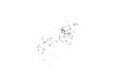
Fig . 1 is an exploded view of an ink j et
printhead structure illustrating alignment between
the ink jet printhead and the eyelid assembly, in
accordance with the present inventioni and
Fig. 2 illustrates achievement of the
precision locational relationship of Fig. 1, between
the eyelid assembly and the catcher, using a

CA 022039~i4 l997-04-29
-4 -
temporary f ixture .
Detailed Descri~tion of the Preferred Embodiments
F~eferring to Figs. 1 and 2, precise
registration between an eyelid assembly and a
continuous ink jet printhead, according to the
present invention, is shown. A typical ink jet
printhead, generally designated 10, includes a
resonator 2, a catcher 3, and an eyelid assembly 1.
An eyelid linkage mechanism, or pivot
plates 4, fasten to and travel with the ink jet
printhead 10. The pivot plates are bonded into
place, such as with an instant adhesive that is
wicked or placed between identified bond sites 8 of
the eyelid linkage 4 and a printhead frame 5. The
pivot plates provide pivot areas that allow the
eyelid assembly 1 to rotate in-and-out of the
catcher 3, thereby diverting ink from the resonator
2 when actuated into the ink path and sealing
against the catcher 3. The eyelid assembly l can be
disconnected from the printhead 10 by pulling a
pivot pin 7, receivable into pivot apertures 13,
from the eyelid assembly 1 and linkage plates 4.
The eyelid assembly 1 stays with the printer and the
linkage plates go with the printhead.
Continuing with Figs. 1 and 2, the
precision design according to the present invention
succeeds by establishing a direct locational
relationship between the catcher 3 and the eyelid
assembly l. This accuracy is ensured by eliminating
screws and their clearance holes, and by fixturing
directly to the catcher 3 via precise alignment
holes 6 located in the bottom of the catcher 3.
Fixture 9 precisely holds and locates the eyelid
links 4, and accurately registers to the catcher

CA 022039~4 1997-04-29
assembly via the catcher alignment holes 6 and
associated mating pins 11. This creates the most
accurate possible relationship between the eyelid
assembly 1 and the catcher 3 by bypassing all of the
hardware between these parts via the f ixture . A
bonding means can then be applied to bond sites 8,
associated with the precisely aligned eyelid
assembly 1 and catcher 3, to permanize the
relationship between these parts. The bonding means
can be any suitable means, including instant
adhes ive .
Referring to Fig. 1, the bond sites 8
preferably have a surface finish of lO0-200 RMS to
enhance mechanical interlocking of the bonding
means. The printhead frame 5 utilizes capillary
channels 12 to feed instant adhesive between the
eyelid links 4 and the printhead frame 5 to the bond
sites 8. An instant adhesive can be pre-applied to
the printhead frame 5 or the eyelid links 4, as long
as the positioning of the parts takes place before
the adhesive dries, typically within 45 seconds.
Industrial ApplicabilitY and
Advantaqes
The present invention is useful in the
field of ink jet printing, and has the advantage of
maximizing print quality by allowing the print media
to be particularly close to the printer. The
present invention provides the further advantage of
providing a precisely registered sealing surface
between the eyelid assembly and the printhead.
Finally, the registration system and method of the
present invention provides the advantage of
eliminating screws, thereby saving labor and
3 5 assembly costs .

CA 022039~i4 1997-04-29
-- 6 --
Having descrlbed the invention in detail
and by reference to the preferred embodiment
thereof, it will be apparent that other
modifications and variations are possible without
s departing from the scope of the invention defined in
the appended claims.

Representative Drawing
A single figure which represents the drawing illustrating the invention.
Administrative Status

2024-08-01:As part of the Next Generation Patents (NGP) transition, the Canadian Patents Database (CPD) now contains a more detailed Event History, which replicates the Event Log of our new back-office solution.

Please note that "Inactive:" events refers to events no longer in use in our new back-office solution.

For a clearer understanding of the status of the application/patent presented on this page, the site Disclaimer , as well as the definitions for Patent , Event History , Maintenance Fee  and Payment History  should be consulted.

Event History

Description Date
Inactive: IPC from MCD 2006-03-12
Application Not Reinstated by Deadline 2004-04-29
Time Limit for Reversal Expired 2004-04-29
Deemed Abandoned - Failure to Respond to Maintenance Fee Notice 2003-04-29
Letter Sent 2002-05-22
Request for Examination Received 2002-04-16
Amendment Received - Voluntary Amendment 2002-04-16
All Requirements for Examination Determined Compliant 2002-04-16
Request for Examination Requirements Determined Compliant 2002-04-16
Letter Sent 1998-02-25
Application Published (Open to Public Inspection) 1997-10-30
Inactive: Single transfer 1997-10-22
Amendment Received - Voluntary Amendment 1997-10-22
Inactive: First IPC assigned 1997-08-01
Inactive: IPC assigned 1997-08-01
Filing Requirements Determined Compliant 1997-07-23
Inactive: Filing certificate - No RFE (English) 1997-07-23
Inactive: Courtesy letter - Evidence 1997-05-27

Abandonment History

Abandonment Date Reason Reinstatement Date
2003-04-29

Maintenance Fee

The last payment was received on 2002-04-08

Note : If the full payment has not been received on or before the date indicated, a further fee may be required which may be one of the following

  • the reinstatement fee;
  • the late payment fee; or
  • additional fee to reverse deemed expiry.

Please refer to the CIPO Patent Fees web page to see all current fee amounts.

Fee History

Fee Type Anniversary Year Due Date Paid Date
Application fee - standard 1997-04-29
Registration of a document 1997-10-22
MF (application, 2nd anniv.) - standard 02 1999-04-29 1999-03-17
MF (application, 3rd anniv.) - standard 03 2000-05-01 2000-03-27
MF (application, 4th anniv.) - standard 04 2001-04-30 2001-03-21
MF (application, 5th anniv.) - standard 05 2002-04-29 2002-04-08
Request for examination - standard 2002-04-16
Owners on Record

Note: Records showing the ownership history in alphabetical order.

Current Owners on Record
SCITEX DIGITAL PRINTING, INC.
Past Owners on Record
BRUCE A. BOWLING
SCOTT D. AYERS
Past Owners that do not appear in the "Owners on Record" listing will appear in other documentation within the application.
Documents

To view selected files, please enter reCAPTCHA code :


To view images, click a link in the Document Description column. To download the documents, select one or more checkboxes in the first column and then click the "Download Selected in PDF format (Zip Archive)" or the "Download Selected as Single PDF" button.

List of published and non-published patent-specific documents on the CPD .

If you have any difficulty accessing content, you can call the Client Service Centre at 1-866-997-1936 or send them an e-mail at CIPO Client Service Centre.


Document
Description 
Date
(yyyy-mm-dd) 
Number of pages   Size of Image (KB) 
Representative drawing 1997-12-09 1 6
Cover Page 1997-12-09 1 44
Abstract 1997-04-29 1 15
Description 1997-04-29 6 186
Drawings 1997-04-29 2 33
Claims 1997-04-29 2 33
Drawings 1997-10-22 1 31
Filing Certificate (English) 1997-07-23 1 165
Courtesy - Certificate of registration (related document(s)) 1998-02-25 1 118
Reminder of maintenance fee due 1998-12-30 1 110
Reminder - Request for Examination 2002-01-02 1 117
Acknowledgement of Request for Examination 2002-05-22 1 179
Courtesy - Abandonment Letter (Maintenance Fee) 2003-05-27 1 176
Correspondence 1997-05-27 1 34