Language selection

Search

Patent 2203987 Summary

Third-party information liability

Some of the information on this Web page has been provided by external sources. The Government of Canada is not responsible for the accuracy, reliability or currency of the information supplied by external sources. Users wishing to rely upon this information should consult directly with the source of the information. Content provided by external sources is not subject to official languages, privacy and accessibility requirements.

Claims and Abstract availability

Any discrepancies in the text and image of the Claims and Abstract are due to differing posting times. Text of the Claims and Abstract are posted:

  • At the time the application is open to public inspection;
  • At the time of issue of the patent (grant).
(12) Patent: (11) CA 2203987
(54) English Title: WASHING MACHINE PULLEY AND FLUID RING
(54) French Title: POULIE ET ANNEAU DE BALANCE DE MACHINE A LAVER
Status: Expired and beyond the Period of Reversal
Bibliographic Data
(51) International Patent Classification (IPC):
  • D06F 37/24 (2006.01)
  • D06F 37/22 (2006.01)
(72) Inventors :
  • VANDE HAAR, EVAN R. (United States of America)
(73) Owners :
  • MAYTAG CORPORATION
(71) Applicants :
  • MAYTAG CORPORATION (United States of America)
(74) Agent: FINLAYSON & SINGLEHURST
(74) Associate agent:
(45) Issued: 2002-10-08
(22) Filed Date: 1997-04-29
(41) Open to Public Inspection: 1997-12-05
Examination requested: 1999-07-15
Availability of licence: N/A
Dedicated to the Public: N/A
(25) Language of filing: English

Patent Cooperation Treaty (PCT): No

(30) Application Priority Data:
Application No. Country/Territory Date
08/659,170 (United States of America) 1996-06-05

Abstracts

English Abstract


An improved clothes washing machine is provided
with a one-piece pulley and fluid balance ring. The
fluid ring is integrally formed with the pulley and is
cantilevered from the pulley. The fluid ring is thus
in an offset vertical plane relative to the belt track
of the pulley so as to prevent interference with the
pulley belt. The fluid ring includes a plurality of
concentric annular fluid chambers each of which-are
partially filled with fluid to provide a counterbalance
to an unbalanced load of clothes in the washing
machine. In an alternative embodiment, the fluid ring
is integrally formed with the pulley and spaced
radially inwardly from the pulley belt track.


Claims

Note: Claims are shown in the official language in which they were submitted.

The embodiments of the invention in which an exclusive
property or privilege is claimed are defined as follows:
1. A clothes washing machine comprising:
a cabinet;
a tub supported in the cabinet;
a drum rotatably mounted within the tub and adapted to
receive clothes to be washed;
a drum shaft extending axially from the drum and defining
an axis of rotation for the drum;
a motor within the cabinet with a rotatable drive shaft
extending from the motor;
a drive pulley mounted on the drive shaft;
a driven pulley mounted on the drum shaft;
a pulley belt trained about the drive pulley and the
driven pulley for imparting rotation to the drum;
a fluid balance ring extending from the driven pulley.
2. The clothes washing machine of claim 1 wherein the fluid
balance ring is formed integrally with the driven pulley.
3. The clothes washing machine of claim 1 wherein the fluid
balance ring extends radially from the driven pulley.
4. The clothes washing machine of claim 1 wherein the fluid
balance ring has a diameter greater than the diameter of the
driven pulley.
5. The clothes washing machine of claim 1 wherein the fluid
balance ring has a diameter smaller than the diameter of the
driven pulley.
6. The clothes washing machine of claim 1 wherein the fluid
balance ring extends axially from the driven pulley.
7

7. The clothes washing machine of claim 1 wherein the fluid
balance ring includes multiple annular fluid chambers each
being partially filled with fluid.
8. The clothes washing machine of claim 1 wherein the fluid
balance ring includes a plurality of concentric annular
chambers molded integrally with the driven pulley, and a lid
sealably mounted over the chambers to retain fluid therein.
9. The clothes washing machine of claim 1 wherein the driven
pulley has a belt track for engaging the pulley belt and the
fluid balance ring is offset with respect to the belt track.
10. An improved clothes washer having a rotatable drum for
receiving clothes to be washed and a drive motor for rotating
the drum, the improvement comprising:
a pulley for operatively connecting the drive motor to
the drum; and
a fluid balance ring integrally formed with the pulley.
8

11. The improved clothes washer of claim 10 wherein
the fluid balance ring extends axially and radially
from the pulley.
12. The improved clothes washer of claim 10 wherein
the fluid balance ring includes a plurality of
concentric annular chambers each being partially filled
with fluid.
13. The improved clothes washer of claim 10 wherein
the fluid balance ring is located radially outward from
the pulley.
14. The improved clothes washer of claim 10 wherein
the fluid balance ring is located radially inwardly
from the pulley.
15. A method of balancing an unbalanced load of
clothes in a washing machine, the machine including a
rotatable drum for holding the clothes being washed, a
motor to rotate the drum, and a pulley to drivingly
connect the motor and the drum, the method comprising:
extending a fluid balance ring from the pulley for
rotation with the drum, the ring including at
least one annular chamber; and
partially filling the chamber with fluid whereby the
fluid will counterbalance an unbalanced load
during rotation of the drum and ring.
9

Description

Note: Descriptions are shown in the official language in which they were submitted.


CA 02203987 1997-04-29
WASHING MACHINE PULLEY AND FLUID RING
BACKGROUND OF THE INVENTION
Clothes washing machines commonly are provided
with a fluid ring to correct or counterbalance
unbalanced loads during the spin and wash operations.
The fluid rings are normally mounted at the top edge of
a vertical axis drum or the front edge of a horizontal
axis drum with a front access opening. Other prior art
washing machines include fluid balance rings along the
side wall of a vertical access drum (U. S. Patent
3,494,471), or around the perimeter of the end walls of
a horizontal access drum having an access opening in
the cylindrical side wall (U. S. Patent 5,345,792).
Balance rings have also been provided near the rear
wall of a horizontal access drum (U. S. Patent
3,330,168).
One objective in all known prior art fluid balance
rings is to space the ring radially a maximum distance
from the rotational axis of the drum so as to obtain
the maximum counterbalance effect. In such prior art
devices, the fluid ring is a separate component which
is attached to the drum or the rotating drive shaft of
the drum in various ways. Such construction increases
the manufacturing costs, due to the multiple components
and assembly thereof.
Another objective in counterbalancing devices is
to space the counterbalancing ring axially a maximum
distance from the pivot point of the drum. The pivot
point is typically the bearing support. By extending
axially a maximum distance, the effect of the
counterbalance is maximized. While prior art devices
commonly mount to the open end of the drum, this leaves
the rear of the drum without any counter balancing
mechanism.
1

CA 02203987 1999-10-26
Therefore, a primary aspect of the present invention
seeks to provide an improved fluid ring for washing machines.
Another aspect of the present invention seeks the
provision of a fluid ring formed integrally with the pulley of
a washing machine associated with driving the drum.
Another aspect of the present invention seeks the
provision of a washing machine pulley associated with the drum
and fluid ring having a one-piece molded construction.
Another aspect of the present invention is the
provision of a fluid ring cantilevered from the driven pulley
of a washing machine which counterbalances an unbalanced load
during the operation of the machine.
SUMMARY OF THE INVENTION
An integrally formed pulley and fluid ring is provided
for a clothes washing machine to balance unbalanced loads
during the operation of the machine. The washing machine
includes a conventional drum rotatably mounted in a cabinet. A
shaft extends axially from the drum and defines the axis of
rotation for the drum. A motor with a rotatable drive shaft is
mounted in the cabinet.
The invention in one broad aspect provides a clothes
washer having a rotatable drum for receiving clothes to be
washed and a drive motor for rotating the drum, the
improvement comprising a pulley for operatively connecting the
drive motor to the drum, and a fluid balance ring integrally
formed with the pulley.
Further the invention comprehends a method of balancing
an unbalanced load of clothes in a washing machine, the
machine including a rotatable drum for holding the clothes
being washed, a motor to rotate the drum, and a pulley to
drivingly connect the motor and the drum, the method
comprising extending a fluid balance ring from the pulley for
rotation with the drum, the ring including at least one
2

" CA 02203987 1999-10-26
annular chamber, and partially filling the chamber with fluid
whereby the fluid will counterbalance an unbalanced load
during rotation of the drum and ring.
More particularly, the pulley and fluid ring combination
of the present invention is mounted on the drum shaft and
drivingly connected to the motor by a pulley belt. The fluid
ring is cantilevered from the pulley so as to be offset, and
thereby avoid any interference with the pulley belt. The fluid
ring is formed integrally with the pulley, and includes a
plurality of concentric annular chambers. A lid is sealingly
mounted or welded to the fluid chamber to retain the fluid
therein.
2A

CA 02203987 1997-04-29
BRIEF DESCRIPTION OF THE DRAWINGS
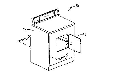
Figure 1 is a perspective view of a horizontal
axis washing machine.
Figure 2 is a sectional view taken along lines 2-2
of Figure 1 and showing a first embodiment of the
combined pulley and fluid ring of the present
invention.
Figure 3 is a perspective view of the pulley and
fluid ring.
Figure 4 is a front elevation view of the pulley
and fluid ring.
Figure 5 is a sectional view taken along lines 5-5
of Figure 4.
Figure 6 is a sectional view of the fluid ring
lid.
Figure 7 is a perspective view of a second
embodiment of the combined pulley and fluid ring of the
present invention.
Figure 8 is a front elevation view of the
alternative embodiment.
Figure 9 is a sectional view taken along lines 9-9
of Figure 8.
DETAILED DESCRIPTION OF THE DRAWINGS
A horizontal washing machine is generally
designated by the reference numeral 10 in the drawings.
The washing machine 10 includes a cabinet 12 with a
door 14 movable between open and closed positions
relative to a front opening 16. The base 18 of the
washing machine includes a plurality of struts or
supports 20 for supporting a tub 22 within the cabinet.
A perforated drum 26 is rotatably mounted within the
tub 22 and has an open forward end through which
clothes are placed into the drum and removed therefrom.
A water tight seal is provided between the perimeter
3

CA 02203987 1997-04-29
edge 24 of the tub 22 and the door 14 when the door is
in the closed position. Water inlet and outlet lines
(not shown) are operatively connected to the tub 22 so
that wash and rinse water can be supplied to the
clothes in the drum 26 and drained from the tub 22.
During the operation of the machine 10, the water in
the tub 22 never rises to a level above the access
opening 16 in the cabinet 12. The water tight seal
between the tub 22 and the door 14 prevents splash out
of water. A motor 28 is mounted in the cabinet 12, and
includes a drive shaft 30 for imparting rotation to the
drum 26, as described further below. The drum 26 is
mounted on a rotational support shaft 27, which is
journalled within bearings 29 in the rear of the tub
22, as seen in Figure 2.
The components of the washing machine 10, as
described above, are conventional and do not constitute
a part of the present invention.
The present invention is directed towards a
combination pulley and fluid ring. More particularly,
a driven pulley 32 is integrally formed through one-
piece molded construction with a fluid ring 34. The
pulley 32 is driven by a belt 36 trained about the
pulley 32 and a pulley 38 on the drive shaft 30 of the
motor 28. By forming the fluid ring 34 integrally with
the pulley 32, the fluid ring 34 can be maintained a
maximum axial extension from the bearings 29.
The fluid ring 34 extends radially and axially
from the pulley 32. As best seen in Figures 2 and 5,
the fluid ring 34 is cantilevered forwardly from the
pulley 32 so as to be offset therefrom. Thus, the
fluid ring 34 does not interfere with the pulley belt
36.
The fluid ring 34 includes a plurality of
concentric annular chambers 40, each of which are
4

CA 02203987 1997-04-29
partially filled with a fluid. A lid or cover 42 is
sealingly mounted over the chambers 40 by plastic
welding or other convenient means. The lid 42 includes
a central opening 43 to fit over the pulley 32.
The pulley 32 includes a central hub 44 so that
the combination pulley and fluid ring is mountable upon
the shaft 27 extending from the rear of the drum 26. A
plurality of spokes 46 extend radially from the tub to
the pulley track 48 of the pulley 32.
In the operation of the washing machine 10, the
motor 28 functions to rotate the drum 26 within the tub
22 via the pulleys 32, 38 and the pulley belt 36. If
an unbalanced load of clothes develops within the drum
26, the fluid within the fluid chambers 40 moves to a
position within the chambers opposite the unbalanced
clothes load, thereby correcting or counterbalancing
the distribution of the load relative to the bearings
31.
In an alternative embodiment shown in Figure 7,
the pulley 50 has a large diameter and the fluid
balance ring 52 is integrally foamed within the
circumference of the pulley 50. The ring 52 has
concentric fluid chambers 54. With the ring 52 spaced
radially inwardly from the pulley track 56, there is no
interference with the belt 36. Also, the ring 52 is
not cantilevered from the pulley 50, as in the first
embodiment. A hub 58 is provided for mounting the
combined pulley and ring to the support shaft 27. A
disc wall 60 extends between the tub 58 and the belt
track 56.
Whereas the invention has been shown and described
in connection with the preferred embodiments thereof,
it will be understood that many modifications,
substitutions, and additions may be made which are
within the intended broad scope of the following
5

CA 02203987 1997-04-29
claims. From the foregoing, it can be seen that the
present invention accomplishes at least all of the
stated objectives.
6

Representative Drawing
A single figure which represents the drawing illustrating the invention.
Administrative Status

2024-08-01:As part of the Next Generation Patents (NGP) transition, the Canadian Patents Database (CPD) now contains a more detailed Event History, which replicates the Event Log of our new back-office solution.

Please note that "Inactive:" events refers to events no longer in use in our new back-office solution.

For a clearer understanding of the status of the application/patent presented on this page, the site Disclaimer , as well as the definitions for Patent , Event History , Maintenance Fee  and Payment History  should be consulted.

Event History

Description Date
Time Limit for Reversal Expired 2007-04-30
Letter Sent 2006-05-01
Inactive: IPC from MCD 2006-03-12
Grant by Issuance 2002-10-08
Inactive: Cover page published 2002-10-07
Inactive: Final fee received 2002-07-30
Pre-grant 2002-07-30
Notice of Allowance is Issued 2002-07-16
Letter Sent 2002-07-16
Notice of Allowance is Issued 2002-07-16
Inactive: Approved for allowance (AFA) 2002-07-05
Amendment Received - Voluntary Amendment 2001-12-28
Inactive: S.30(2) Rules - Examiner requisition 2001-07-05
Amendment Received - Voluntary Amendment 1999-10-26
Inactive: Cover page published 1999-10-05
Letter Sent 1999-08-05
Request for Examination Received 1999-07-15
Request for Examination Requirements Determined Compliant 1999-07-15
All Requirements for Examination Determined Compliant 1999-07-15
Application Published (Open to Public Inspection) 1997-12-05
Inactive: First IPC assigned 1997-08-04
Inactive: IPC assigned 1997-08-04
Letter Sent 1997-07-24
Inactive: Filing certificate - No RFE (English) 1997-07-24

Abandonment History

There is no abandonment history.

Maintenance Fee

The last payment was received on 2001-12-14

Note : If the full payment has not been received on or before the date indicated, a further fee may be required which may be one of the following

  • the reinstatement fee;
  • the late payment fee; or
  • additional fee to reverse deemed expiry.

Patent fees are adjusted on the 1st of January every year. The amounts above are the current amounts if received by December 31 of the current year.
Please refer to the CIPO Patent Fees web page to see all current fee amounts.

Owners on Record

Note: Records showing the ownership history in alphabetical order.

Current Owners on Record
MAYTAG CORPORATION
Past Owners on Record
EVAN R. VANDE HAAR
Past Owners that do not appear in the "Owners on Record" listing will appear in other documentation within the application.
Documents

To view selected files, please enter reCAPTCHA code :


To view images, click a link in the Document Description column. To download the documents, select one or more checkboxes in the first column and then click the "Download Selected in PDF format (Zip Archive)" or the "Download Selected as Single PDF" button.

List of published and non-published patent-specific documents on the CPD .

If you have any difficulty accessing content, you can call the Client Service Centre at 1-866-997-1936 or send them an e-mail at CIPO Client Service Centre.


Document
Description 
Date
(yyyy-mm-dd) 
Number of pages   Size of Image (KB) 
Description 1997-04-28 6 193
Abstract 1997-04-28 1 19
Claims 1997-04-28 4 92
Drawings 1997-04-28 5 127
Claims 1999-10-25 3 89
Description 1999-10-25 7 224
Representative drawing 1999-03-18 1 6
Description 2002-10-06 7 224
Drawings 2002-10-06 5 127
Abstract 2002-10-06 1 19
Courtesy - Certificate of registration (related document(s)) 1997-07-23 1 118
Filing Certificate (English) 1997-07-23 1 165
Reminder of maintenance fee due 1998-12-29 1 110
Acknowledgement of Request for Examination 1999-08-04 1 193
Commissioner's Notice - Application Found Allowable 2002-07-15 1 164
Maintenance Fee Notice 2006-06-26 1 172
Correspondence 2002-07-28 1 31