Language selection

Search

Patent 2204054 Summary

Third-party information liability

Some of the information on this Web page has been provided by external sources. The Government of Canada is not responsible for the accuracy, reliability or currency of the information supplied by external sources. Users wishing to rely upon this information should consult directly with the source of the information. Content provided by external sources is not subject to official languages, privacy and accessibility requirements.

Claims and Abstract availability

Any discrepancies in the text and image of the Claims and Abstract are due to differing posting times. Text of the Claims and Abstract are posted:

  • At the time the application is open to public inspection;
  • At the time of issue of the patent (grant).
(12) Patent: (11) CA 2204054
(54) English Title: FROTH SEPARATION APPARATUS
(54) French Title: APPAREIL DE SEPARATION DE L'ECUME
Status: Expired and beyond the Period of Reversal
Bibliographic Data
(51) International Patent Classification (IPC):
  • B01D 19/00 (2006.01)
(72) Inventors :
(73) Owners :
  • SUPAFLO TECHNOLOGIES PTY. LTD
(71) Applicants :
  • SUPAFLO TECHNOLOGIES PTY. LTD (Australia)
(74) Agent: MARTINEAU IP
(74) Associate agent:
(45) Issued: 2007-01-09
(22) Filed Date: 1997-04-30
(41) Open to Public Inspection: 1997-11-01
Examination requested: 2002-04-19
Availability of licence: N/A
Dedicated to the Public: N/A
(25) Language of filing: English

Patent Cooperation Treaty (PCT): No

(30) Application Priority Data:
Application No. Country/Territory Date
PN 9609 (Australia) 1996-05-01

Abstracts

English Abstract


An apparatus (1) for gating froth from liquid. The apparatus (1) comprises a
feed
conduit (3) to carry partially aerated feed liquid, and separation means to
receive and
separate the feed liquid into a first component consisting substantially of
froth or gas and a
second component consisting substantially of de-aerated liquid or sludge.


Claims

Note: Claims are shown in the official language in which they were submitted.

-7-
CLAIMS
THE EMBODIMENTS OF THE INVENTION, IN WHICH AN EXCLUSIVE PROPERTY OF
PRIVILEGE IS CLAIMED, ARE DEFINED AS FOLLOWS:
1. An apparatus for separating froth from liquid, said apparatus comprising:
a first conduit to carry partially aerated feed liquid;
a centrifugal separator receiving and separating the partially aerated feed
liquid, by
inducing a rotational flow of the feed liquid in a separation chamber, into a
first
component comprising froth or gas as an overflow stream from said separator,
and a
second component comprising de-aerated liquid or sludge as an underflow stream
from
said separator; and
a second conduit for carrying the second component to a downstream process
unit.
2. The apparatus according to claim 1, wherein said centrifugal separator is a
cyclonic separator.
3. The apparatus according to claim 1 or claim2, wherein said centrifugal
separator
comprises a bank of centrifugal separators connected in series or parallel.
4. The apparatus according to any one of claims 1 to 3, further including an
array of
liquid spray jets positioned to spray a liquid onto and break down the first
component
into a third component comprising a liquid.
5. The apparatus according to claim 4, wherein the third component is added to
the
second component downstream of said centrifugal separator.
6. The apparatus according to claim 4, wherein the third component is recycled
upstream of said centrifugal separator and to the feed liquid.
7. The apparatus according to any one of claims 1 to 6, wherein the first
component
is substantially collapsed within said centrifugal separator and the overflow
stream
comprises gas.
8. An apparatus for removal of flotation froth and air from a feed stream,
said
apparatus comprising:

-8-
a first conduit for carrying a partially aerated feed liquid;
a centrifugal separator receiving the partially aerated feed liquid for
inducing a
rotational flow of the feed liquid in a separation chamber to separate the
partially
aerated feed liquid into a first component comprising froth or gas as an
overflow stream
from said centrifugal separator and a second component comprising de-aerated
liquid or
sludge to produce an underflow stream from said centrifugal separator;
a second conduit for carrying the second component to a thickener; and
a thickener comprising a tank in which a dispersed solid component tends to
settle
from solution or suspension toward a lower region of the tank, to be drawn off
from
below the tank, and a relatively dilute liquor is displaced toward an upper
region of the
tank for removal via an overflow launder.
9. A method for separating froth from liquid, said method comprising the steps
of:
conveying a partially aerated feed liquid to separation means, and
centrifugally separating the feed liquid in the separation means, by inducing
a
rotational flow of the feed liquid in a separation chamber, into a first
component
comprising froth or gas, to produce an overflow stream from the separation
means, and
a second component comprising de-aerated liquid or sludge, to produce an
underflow
stream from the separation means.
10. The method according to claim 9, including centrifugally separating the
feed
liquid in a cyclonic separator.
11. The method according to claim 9 or claim 10, including centrifugally
separating
the feed liquid in a bank of centrifugal separators connected in series or
parallel.
12. The method according to any one of claims 9 to 11, including breaking down
any
froth remaining after centrifugal separating into a third component comprising
liquid, by
spraying the froth with liquid through an array of spray jets.
13. The method according to claim 12, including adding the third component to
the
second component, after centrifugally separating the feed liquid.

-9-
14. The method according to claim 12, including recycling the third component,
before centrifugally separating the feed liquid, by adding the third component
to the feed
liquid.
15. The method according to any one of claims 9 to 14, including substantially
collapsing the froth in the first component within the separation means so
that the
overflow stream comprises gas.
16. A method for separating flotation froth and air from a feedstream, said
method
comprising:
conveying a feed stream to separation means;
centrifugally separating the feed liquid in the separation means, by inducing
a
rotational flow of the feed liquid in a separation chamber, into a first
component
comprising froth or gas, to produce an overflow stream from the separation
means, and
a second component comprising de-aerated liquid or sludge, to produce an
underflow
stream from the separation means;
conveying the underflow stream to a thickener; and
separating a solid component dispersed in the underflow stream from the
underflow stream by settling in a thickener tank, for drawing off from below
the tank,
with a relatively dilute liquor being displaced upwardly in the tank for
removal via an
overflow launder.

Description

Note: Descriptions are shown in the official language in which they were submitted.


CA 02204054 1997-04-30
_2_
The present invention relates to a method and apparatus far de-aerating
liquids, or
separating entrained air or froth from liquids or pulps.
The invention has been developed primarily for use with thickeners,
clarifrers, or
concentrators and will be described hereinafter with reference to this
application. It wilt be
appreciated, however, that the invention is not limited to this particular
field of use.
Thickeners, clarifiers and concentrators are typically used for separating
solids from
liquids and are often found in the mining, mineral processing, food
processing, sugar
refining, water treatment, sewage treatment, and other such industries.
These devices typically comprise a tank in which solids are deposited from
to suspension or solution and settle toward the bottom as pulp or sludge to be
drawn off'from
below and recovered. A dilute liquor of lower relative density is thereby
displaced toward
the top of the tank, for removal via an overflow launder. The liquid to be
thickened is
initially fed through a feedline into a feedwell disposed within the main
tank. The purpose
of the feedwell is to ensure relatively uniform distribution and to prevent
turbulence from
t s the incoming feed liquid from disturbing the settling process taking Place
within the
surrounding tank.
In cases where the feed liquid wmpr3ses flotation concentrate, it is normally
at least
partially aerated. The air bubbles, if allowed to pass from the feedwelI into
the main tank,
tend to produce a considerable amount of relatively stable froth on the
surface of both the
2o feedwell and the thickener. This froth can contain a significant proportion
of entrained
solids and thereby tends to reduce the separation efficiency of the thickener.
In addition,
air bubbles can become trapped in the sludge, resulting in slower settling
rates and lower
underflow densities, both of which reduce separation eft'rciency fiuther
stilt.

CA 02204054 1997-04-30
-3-
It is an object of the present invention to overcome or substantially
ameliorate this
problem in the prior art.
Accordingly, the invention as presently contemplated consists in an apparatus
for
separating froth from liquid, said apparatus comprising a feed conduit to
carry partially
s aerated feed liquid, and separation means to receive and separate said feed
liquid into a
first component consisting substantially of froth or gas and a second
component consisting
substantially of de-aerated &quid or sludge.
Preferably, the separation mesas include a centrifugal separator adapted to
induce
rotational flow of the feed liquid in a separation chamber whereby the froth
or gas
t0 component emerges as overflow frnm the separator and the liquid or sludge
compone~
emerges as underflow from the separator. A bank of separators connected in
series,
parallel or a combination of both, may be used to achieve the desired level of
separation.
Jn one preferred embodiment, the centrifugal separator is a cyclone separator.
The apparatus preferably further includes an array of liquid spray jets
positioned to
I5 break down any froth following separation into a third component consisting
substantially
of liquid, which optionally may be added to the second liquid or sludge
component
downstream of the separator or recycled upstream thereof into the feed Liquid.
In a second aspect, the invention consists in a method for separating froth
from
liquid, said method comprising the steps of conveying a partially aerated feed
liquid to
20 separation mesas, and separating said feed liquid into a first component
consisting
substantially of froth or gas and a second component consisting substantially
of de-aerated
liquid or sludge.

CA 02204054 1997-04-30
-4-
preferably, the feed liquid is separated by means of a centtifttgal separator
disposed
such that the froth or gas component emerges from the separator overflow and
the liquid or
sludge component emerges firm the separator underfiow.
The method preferably comprises the fiuther step of breaking down any froth
component by means of liquid spray jets into a third component consisting
substantially of
liquid.
Optionally, the method comprises the fiuther step of recombining the third
liquid
component with tire second liquid component downstream of the separator or
with the feed
liquid upstteam thereof. Alternatively, the overflow and undetflow from the
centrifugal
to separator may be directed to separate downstream ptrocess units.
In the preferred embodiment of both aspects, the invention is used for removal
of
flotation froth and air from the feed to a thickener. The thickener preferably
comprises a
tank in which a dispersed solid component tends to settle from solution or
suspension
toward a lower region of the tank to be drawn og from below whilst a
relatively dilute
Liquor is thereby displaced Inward an upper region of the tank for separation
via an
averffow launder.
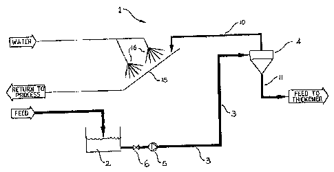
A preferred embodiment of the invention will now be described, by way of
example
only, with reference to the accompanying drawing, which is a schematic flow
diagam
showing the invention as used in conjunction with a thickener.
2o Referring to the drawing, the invention provides an apparatus 1 for
separating liqrad
from froth. The apparatus comprises a sump 2 adapted to receive feed liquid
from an
upstream process, and a feed conduit 3 extending firm the sump to a separation
station 4.
A pump 5 and valve assembly 6 are disposed within the feed conduit 3 to
regulate the flow

CA 02204054 1997-04-30
-5-
of liquid. Alternatively, the separation station 4 may simply TeCeive feed by
gravity flow
from the upstream process.
The separator takes the form of a centrifiigal separation apparatus which bas
been
found, unexpectedly, to be particularly efficient in separating froth from
partially aerated
s pulps by "shearing" the air bubbles from tire solid particles. Whilst a
single separator is
illustrated, it will be appreciated that a plurality of separators connected
in series, parallel
or a combination of both, may also be used depending upon the throughput, the
degree of
separation required, and other variables. In one preferred form of the
invention, a cyclone
type centrifugal separator is used.
Io Within the centrifugal separator 4, the feed liquid is split between the
overflow line
and the underflow line 11. The split betw~n these lines 10 and I 1 can be
controlled as
appropriate by varying several operating parameters of the centrifugal
separator including
the diameter of the separator, the separator length, the angle of the
separator lmrrel, the size
of the inlet undertlow and internai nozzles, the feed pressure and the feed
density. In
testing it has been found, somewhat surprisingly, than with a pattiafly
aerated feed liquid,
and appropriately tuned operating parameters, a relatively small overflow
stream can be
produced which contains the vast majority of the froth, leaving a
proportionately large
volume of de-aerated undertlow liquid having a density similar to that of the
feed liquid.
In the preferred embodiment of the invention, the undetflow line 11 feeds the
de-
aerated liquid from the centrifugal separator to a thickener. This obviates
the problem of
accumulation of excess froth in the thickener and the associated feedwell,
which in prior arI
devices significantly reduces the efficiency of the thickening process. the
froth stream
from the centrifugal separator overflow line 10 is fed to a launder 15 and
broken down with
fine water spray jets L6. This produces a third component consisting of liquid
from the.

CA 02204054 1997-04-30
-6-
spray jets mixes with the liquid froth the collapsed froth, which may be
combined with the
underflow liquid downstream of the centrifugal separator and thence fed to the
thickener,
or else recycled to the feed liquid upstream of the cecrtrifugal separator.
It has also been found, again quite unexpectedly, that by appropriately
controlling
various process parameters of the separator, including flow rate, viscosity,
density, dilution
ratio, rotational speed, chamber shape, and the like, the froth can be
substantially collapsed
within the separator such that the overflow stream consists substantially of
gas, in which
case the supplementary spray jets 16 are not required.
Of course, it will be appreciated that the centrifugal separator aaangement
need not
to necessarily be applied only to thickeners, since the principle of
d~aeration performed by
the centrifugal separators may be used in numerous other applications. There
is also no
specific requirement to recombine the overflow from the cent<ifitgal separator
with the
undertlow or with the feed material. The separated streams may simply be
directed to
discrete downstream process units as required. There is also no need for pumps
if
sufficient pressure head is otherwise available.
Although the invention has been described with reference to specific examples,
it
will be appreciated by those skilled in the art that the invention may be
embodied is many
other forms.

Representative Drawing
A single figure which represents the drawing illustrating the invention.
Administrative Status

2024-08-01:As part of the Next Generation Patents (NGP) transition, the Canadian Patents Database (CPD) now contains a more detailed Event History, which replicates the Event Log of our new back-office solution.

Please note that "Inactive:" events refers to events no longer in use in our new back-office solution.

For a clearer understanding of the status of the application/patent presented on this page, the site Disclaimer , as well as the definitions for Patent , Event History , Maintenance Fee  and Payment History  should be consulted.

Event History

Description Date
Time Limit for Reversal Expired 2012-04-30
Letter Sent 2011-05-02
Grant by Issuance 2007-01-09
Inactive: Cover page published 2007-01-08
Inactive: Final fee received 2006-10-26
Pre-grant 2006-10-26
Notice of Allowance is Issued 2006-06-06
Letter Sent 2006-06-06
Notice of Allowance is Issued 2006-06-06
Inactive: Approved for allowance (AFA) 2006-03-08
Amendment Received - Voluntary Amendment 2005-08-04
Inactive: S.30(2) Rules - Examiner requisition 2005-03-02
Amendment Received - Voluntary Amendment 2002-07-26
Letter Sent 2002-05-31
Request for Examination Requirements Determined Compliant 2002-04-19
All Requirements for Examination Determined Compliant 2002-04-19
Request for Examination Received 2002-04-19
Application Published (Open to Public Inspection) 1997-11-01
Letter Sent 1997-10-27
Inactive: Single transfer 1997-08-22
Inactive: First IPC assigned 1997-08-06
Inactive: IPC assigned 1997-08-06
Inactive: Inventor deleted 1997-07-24
Inactive: Filing certificate - No RFE (English) 1997-07-24
Inactive: Applicant deleted 1997-07-24

Abandonment History

There is no abandonment history.

Maintenance Fee

The last payment was received on 2006-03-23

Note : If the full payment has not been received on or before the date indicated, a further fee may be required which may be one of the following

  • the reinstatement fee;
  • the late payment fee; or
  • additional fee to reverse deemed expiry.

Patent fees are adjusted on the 1st of January every year. The amounts above are the current amounts if received by December 31 of the current year.
Please refer to the CIPO Patent Fees web page to see all current fee amounts.

Owners on Record

Note: Records showing the ownership history in alphabetical order.

Current Owners on Record
SUPAFLO TECHNOLOGIES PTY. LTD
Past Owners on Record
None
Past Owners that do not appear in the "Owners on Record" listing will appear in other documentation within the application.
Documents

To view selected files, please enter reCAPTCHA code :


To view images, click a link in the Document Description column (Temporarily unavailable). To download the documents, select one or more checkboxes in the first column and then click the "Download Selected in PDF format (Zip Archive)" or the "Download Selected as Single PDF" button.

List of published and non-published patent-specific documents on the CPD .

If you have any difficulty accessing content, you can call the Client Service Centre at 1-866-997-1936 or send them an e-mail at CIPO Client Service Centre.

({010=All Documents, 020=As Filed, 030=As Open to Public Inspection, 040=At Issuance, 050=Examination, 060=Incoming Correspondence, 070=Miscellaneous, 080=Outgoing Correspondence, 090=Payment})


Document
Description 
Date
(yyyy-mm-dd) 
Number of pages   Size of Image (KB) 
Representative drawing 1997-12-17 1 5
Abstract 1997-04-29 1 9
Description 1997-04-29 5 183
Claims 1997-04-29 3 104
Drawings 1997-04-29 1 9
Claims 2005-08-03 3 109
Representative drawing 2006-12-05 1 7
Drawings 2007-01-07 1 9
Description 2007-01-07 5 183
Abstract 2007-01-07 1 9
Filing Certificate (English) 1997-07-23 1 165
Courtesy - Certificate of registration (related document(s)) 1997-10-26 1 116
Reminder of maintenance fee due 1999-01-03 1 110
Reminder - Request for Examination 2002-01-01 1 117
Acknowledgement of Request for Examination 2002-05-30 1 179
Commissioner's Notice - Application Found Allowable 2006-06-05 1 161
Maintenance Fee Notice 2011-06-12 1 171
Fees 2003-03-12 1 24
Fees 1999-01-27 1 32
Fees 2001-03-15 1 28
Fees 2002-03-13 1 31
Fees 2000-03-15 1 28
Fees 2004-03-17 1 22
Fees 2005-03-16 1 25
Fees 2006-03-22 1 31
Correspondence 2006-10-25 1 29