Note: Descriptions are shown in the official language in which they were submitted.
CA 02204093 2003-03-31
TITLE OF THE INVENTION
STAIR-CLIMBING VEHICLE FOR WHEELCHAIR
BACKGROUND OF THE INVENTION
The present invention relates to a stair-climbing
vehicle, in particular to a stair-climbing vehicle for
transporting a wheelchair with a person sitting on.
In fact, the applicant of this application has
suggested a stair-climbing vehicle for wheelchair, which
was disclosed in Japanese Patent Application Laid-open No.
4-154493, as illustrated in Fig. 7. Referring to Fig. 7,
the conventional stair-climbing vehicle comprises a crawler
device a which includes a pair of endless belt crawlers
each extending in the longitudinal direction thereof over
at least two steps of a stairway while climbing up or down
the stairway, a load-carrying platform C for holding a
wheelchair with a person sitting on, two pairs of
travelling wheels C1 (with one pair provided under the
front portion of the load-carrying platform C and another
pair provided under the rear portion thereof), an
extendible and retractable electrical jacking device b for
pivotally raising the load-carrying platform C, an
operation handle d for operating the stair-climbing
vehicle.
When travelling on a horizontal ground surface, the
electrical jacking device b is caused to retract so that
all the travelling wheels C1 will get in contact with
ground surface. When climbing up or down a stairway, a
change-over switch (not
-1-
CA 02204093 2003-03-31
shown) provided on the operation handle d is operated to
cause the electrical jacking device b to extend, so that
the load-carrying platform C is pivotally raised up to form
an angle of 40° with respect with the crawler device a.
In this way, as shown in Fig. 7, a person sitting on
the wheelchair may be moved up or down a stairway with his
wheelchair slightly inclined rearwardly. In practice, in
order to eliminate an uncomfortable or even a terrible
feeling, the load-carrying platform C is designed to be
able to incline rearwardly a little when traveling up or
down a stairway, such that the load-carrying platform C
forms an angle of 5° - 10° with a horizontal plane.
However, when the stair-climbing vehicle is climbing
up or down a stairway which has only a small inclining
angle with a horizontal plane, the loading stand C will be
inclined rearwardly too much if load-carrying platform C
remains an angle of 40° with respect with the crawler
device a. As a result, because the load-carrying platform
is rearwardly inclined too much, a person sitting on the
wheelchair will have an uncomfortable or even a terrible
feeling. In order to solve such a problem, it has been
sugested that an inclination sensing/controlling device be
provided to detect such an angle. But, if an inclination
sensing/controlling device is employed, it will be
unavoidable to cause an increase in the cost for the
manufacture of a stair-climbing vehicle.
-2-
CA 02204093 2003-03-31
SUMMARY OF THE INVENTION
It is an object of the present invention to provide an
improved stair-climbing vehicle for wheelchair, in which a
load-carrying platform for holding a wheelchair may be
easily pivoted to form a desired angle with a crawler
device corresponding to an inclining angle of a stairway,
without causing any increase in the cost for the
manufacture of a stair-climbing vehicle, therefore solving
the above-mentioned problems peculiar to the above-
mentioned prior art.
According to the present invention, there is provided a
stair-climbing vehicle for transporting a wheelchair with a
person sitting on the wheelchair comprising: a crawler
device including a pair of endless belt crawlers disposed
on opposite sides of the vehicle; a vehicle body including
a driving motor for driving the crawler device to enable
the stair-climbing vehicle to climb up or down a stairway;
and a load-carrying platform for mounting a wheelchair,
said load-carrying platform being capable of pivoting about
a horizontal axis relative to said vehicle body, and being
provided above the vehicle body; wherein the vehicle body
and the load-carrying platform are connected with each
other through an extendible and retractable, electrical
jacking device, the load-carrying platform being provided
with an inclination sensor; and wherein the inclination
sensor comprises an inclination sensing element comprising
a tubular member containing a flowable electrically
conductive material and a pair of electrically conductive
terminals, and when the load carrying platform is
horizontal and the inclination sensor is in operation the
electrically conductive material is in contact with the
-3-
CA 02204093 2003-03-31
electrically conductive terminals for outputting an
operation signal, so that the electrical jacking device is
operatively extended to pivot upwardly said load-carrying
platform.
In one aspect of the present invention, the first
inclination sensing element is inclined forming an angle a
with a horizontal line of the load-carrying platform,
preferably the angle a is 13°- 18°. A second inclination
sensing element is inclined forming an angle ~i with an
extended line of the first inclination sensing member,
preferably the angle ,Q is 5° - 10°. In detail, the flowable
electrically conductive material is mercury.
In another aspect of the present invention, the
crawler device includes a front operating member and a rear
operating member, which are connected with each other and
are capable of cooperating into an inverted "V" through a
mutually connected point. Further, a rod of an
extending/retracting electrical jacking device is connected
to the rear operating member near the mutually connected
point, such that the front operating member and the rear
operating member are normally kept straight, but will be
formed into an inverted "V" by retracting movement of the
electrical jacking device, so as to effect a smooth
movement of the stair-climbing vehicle from a stairway to a
horizontal ground surface, or vice versa. The above objects
and features of the present invention will become more
understood from the following description with reference to
the accompanying drawings.
BRIEF DESCRIPTION OF DRAWINGS
-4-
CA 02204093 1997-04-30
Fig. 1 is a side elevation showing a stair-climbing
vehicle for wheelchair, constructed according to the present
invention.
Fig. 2 is a side elevation showing a stair-climbing
vehicle of Fig. l, which is in position immediately before
climbing up a stairway.
Fig. 3 is a side elevation showing a stair-climbing
vehicle of Fig, l, which is beginning to climb a stairway.
Fig. 4 is a side elevation showing a stair-climbing
vehicle of Fig. 1 which is in the halfway of climbing a
stairway.
Fig. 5 is a side elevation showing a stair-climbing
vehicle of Fig. 1, which is arriving at a horizontal floor
from a stairway.
Figs. 6a - 6h indicate electric circuits for controlling
the pivoting movement of the load-carrying platform of the
stair-climbing vehicle of Fig. 1.
Fig. 7 is a side' elevation showing a stair-.climbing
vehicle of a prior art.
DETAILED DESCRIPTION OF THE PREFERRED EMBODIMENTS
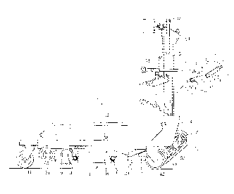
Referring to Fig. 1, a stair-climbing vehicle 1 of the
present invention comprises a vehicle body 2, a crawler
devices 3 including a pair of endless belt crawlers disposed
on opposite sides of the vehicle body 2, a load-carrying
platform 4 provided on the vehicle body 2 so as to be
-5-
CA 02204093 2003-03-31
vertically pivotable about one end thereof. An upright
stand 5 is provided on the rear end of the load-carrying
platform 4, and an inclination sensor 6 is provided on the
upright stand 5.
The crawler device 3 includes a pair of front driving
wheels 31, 31 provided on the front side thereof, a pair of
rear driven wheels 32, 32 provided on the rear side
thereof, and a pair of rotating wheels 33, 33 disposed
close to the rear driven wheels 32, 32. A pair of endless
belt crawlers 34, 34 are arranged to pass around and engage
with the driving wheels 31, 31, the driven wheels 32, 32
and the rotating wheels 32, 32. A driving motor 35 and a
speed reducer 36 are mounted in the front portion of the
vehicle body 2. An extendible and retractable, electrical
jacking device 7 and another extendible and retractable,
electrical jacking device 8 are provided in the vehicle
body 2. Also provided in the vehicle body 2 are battery
for supplying electricity power to the motor 35, the
electrical jacking device 7 and the electrical jacking
device 8. Further, some electric elements 37 are also
mounted on the vehicle body 2.
Between the driving wheels 31, 31 and the rotating
wheels 33, 33 are provided a pair of front operating
members 38, 38 and a pair of rear operating members 39, 39.
The front operating members 38, 38 and the rear operating
members 39, 39 are pivotally supported on the crawler
device 3. Moreover, each front operating member 38 and
each rear operating member 39 are connected with each other
so that they may cooperate to
-6-
CA 02204093 2003-03-31
form an inverted "V" with a connection point f at a top.
The rod portion of the electrical jacking device 7 is
connected to the rear operating member 39 near the .
connection point f. The electrical jacking device 7 may be
operated to extend or retract effected by a signal from the
inclination sensor 6. The sensor 6 is so provided that as
soon as it detects that the stair-climbing vehicle 1 has
climbed up to reach the upmost step of a stairway, the
electrical jacking device 7 will retract.
When the stair-climbing vehicle 1 is travelling on a
horizontal ground surface or climbing up or down a
stairway, the electrical jacking device 7 is caused to
extend, so that a front operating member 38 and a rear
operating frame 39 are kept at a straight line, threby
enabling the stair-climbing vehicle 1 to move in a
stabilized manner. Further, when the stair-climbing
vehicle 1 reaches the upmost step of a stairway, the
vehicle 1 will be changed from an inclined position into a
horizontal position, or vice versa. Such kind of movement
will be detected by the sensor 6 which will then cause the
electrical jacking device 7 to retract. As a result, the
front operating member 38 and the rear operating member 39
will cooperate to form an inverted "V", as shown in Fig. 5.
In this way, since the belt crawler 34 is caused to bend
into an inverted "V", the stair-climbing vehicle 1 does not
have to change a great deal in its traveling position so as
to effect a smooth movement from stairway to horizontal
ground surface or vice versa (see Fig. 5).
CA 02204093 2003-03-31
The load-carrying platform 4 is provided on the
vehicle body 2 and it is pivotable in vertical direction
about the rear end thereof.
The load-carrying platform 4 has a pair of front
casters 41, 41 and a pair of rear casters 42, 42. When
travelling on horizontal ground surface, the electrical
jacking device 8 is retracted, so that the front casters
41, 41 and the rear casters 42, 42 will project beyond the
ground contacting surface of the crawler device 3, upwardly
separating the crawler device 3 from the ground surface,
thereby enabling the vehicle 1 to run on the ground surface
by means of the front caster 41, 41 and the rear caster 42,
42, as illustrated in Fig. 1.
As illustrated in Fig. 2, when the stair-climbing
vehicle 1 is about to climb up a stairway, the electrical
jacking device 8 will extend so as to cause the load-
carrying platform 4 to upwardly pivot about the rear end
thereof, enabling the front casters 41, 41 and the rear
casters 42, 42 to upwardly separate from the ground
surface, making the crawler device 3 to contact with the
ground. In this manner, the vehicle 1 is able to start its
climbing up a stairway by driving the crawler device 3.
The load-carrying platform 4 is constructed to mount a
wheelchair. In fact, a sliding plate (not shown) is
received in the front portion of the load-carrying platform
4. When a wheelchair is about to be mounted on the load-
carrying
_g_
CA 02204093 1997-04-30
platform 4, the sliding plate slides out to serve as a slope
plate between the ground surface and the front portion of the
load-carrying platform 4. Thus, a wheelchair may be moved
from the ground surface through the slope plate onto the load-
carrying platform 4. Further, in order to prevent the
wheelchair from dropping off the load-carrying platform 4, a
pair of safety bars 43, 43 are provided on both sides of the
load-carrying platform 4.
The upright stand 5 is provided on the rear end of the
load-carrying platform 4. A first retaining device 51 and a
second retaining device 52 are provided on the upright stand 5
in order to firmly hold the wheelchair on the load-carrying
platform 4. Further, an operating handle 53 and an
operation panel 54 are provided on the upper portion of the
upright stand 5, thus, when moving the vehicle l, an operator
(person) can grip the handle 53 while performing necessary
operation on the operation panel 54, thereby enabling the
vehicle 1 to move in a desired manner.
One of the most important features of the present
invention is that an inclination sensor 6 which includes a
first inclination sensing element 61 and a second inclination
sensing element 62 is provided on the upright stand 5.
The first inclination sensing element 61 is a tubular member
having at one end thereof a pair of electrically conductive
terminals 61a, 61b. Similarly, the second inclination
sensing element 62 is also a tubular member having at one end
_9_
CA 02204093 2003-03-31
thereof a pair of electrically conductive terminals 62a,
62b. Each of the tubular members contains a flowable
mercury material 61c or 62c having a predetermined quantity
enough to make conductive between the terminals 61a and 61b
or between the terminals 62a and 62b. When the mercury
material 61c or 62c gets in touch with the terminals 61a
and 61b or the terminals 62a and 62b, the terminals 61a and
61b or the terminals 62a and 62b, will become electrically
conducting with each other. As a result, a motor 81 for
driving the electrical jacking device 8 will be energized,
which will be described in more detail later.
As shown in an enlarged part of Fig. 1, the first
inclination sensing element 61 is arranged to form an angle
a with a horizontal plane. Preferably, the angle a is 15°
with the right end of the element 61 being higher as
indicated in the drawing. Further, the second inclination
sensing element 62 is arranged to form an angle a with an
extended line of the first inclination sensing element 61.
Preferably, the angle a is 5° with the right end of the
element 62 being higher as indicated in the drawing.
An electric circuit 9 in connection with the first and
second inclination sensing element 61 and 62 is indicated
in detail in Fig. 6a. As illustrated in Fig. 6a, the
electric circuit 9 includes the terminals 61a, 61b, 62a,
62b, a battery 37, a motor 81 which is used for driving the
electrical jacking device 8. The circuit 9 further
includes a manual switch 91,
-10-
CA 02204093 1997-04-30
electro-magnetic coils 92, 93, change-over switches 94 and 95
operated by the electro-magnetic coils 92, 93. In practice,
the change-over switches 94 and 95 are normally in contact
with points B in the circuit.
The operation of the stair-climbing vehicle 1 will be
described in detail below with reference to Figs. 1 - 5 and
Figs. 6a - 6h.
Referring to Fig. l, when the stair-climbing vehicle 1 is
moving on a horizontal ground surface, the load-carrying
Platform 4 and the vehicle body 2 are in a horizontal and
mutually parallel position, so that the pair of front casters
41, 41 and the pair of rear casters 42, 42 (all provided on
the underside of the load-carrying platform 4) are in contact
with the ground surface.
When the stair-climbing vehicle 1 is about to travel from
the horizontal ground onto a stairway so as to climb up or
down the stairway, the manual switch 91 (connected to and
provided on the surface of the operation panel 54) is switched
ON (Fig. 6b). At this moment, since the first inclination
sensing element 61 is in a position having an angle a 15°
with a horizontal plane, the mercury material 61c will move
downwardly to touch with the terminals 61a and 61b located
at lower end of the tubular member, therefore the terminals
61a and 61b become electrically conductive with each other.
Thus, as shown in Fig. 6b, since the manual switch 91 is ON
(in contact with side A), the electro-magnetic coil 92 will be
-11-
CA 02204093 2003-03-31
energized to generate a magnetic attracting force, so ws to
cause the change-over switch 94 to get in contact with side
A. consequently, the motor 81 will begin to rotate in one
predetermined direction so that the electrical jacking
device 8 will extend. Then, as fast as the load-carrying
platform 4 is pivoted upwardly to form an angle of 15° with
the vehicle body 2, the flowable mercury material 61c will
move to the other end of the cylindrical member, so that
the circuit 9 will be interrupted and the motor 81 will
stop, as shown in Fig. 6c.
At this moment, the vehicle 1 will be in position
shown in Fig. 2. As shown in Fig. 2, since the load-
carrying platform 4 is pivoted upwardly to form an angle
with the vehicle body 2, the front casters 41, 41 and the
rear casters 42, 42 will be raised so as to be separated
from the ground surface, causing the crawler device 3 to
contact with the ground surface. With the load-carrying
platform 4 inclined rearwardly forming an angle of 15° with
the vehicle body 2, a person sitting on a wheelchair will
not have an uncomfortable or a terrible feeling while the
vehicle 1 is climbing up or down a stairway.
Referring to Fig. 3, when the stair-climbing vehicle 1
has begun its climbing up or down a stairway by driving its
crawler device 3, the load-carrying platform 4 is pivoted
upwardly still further. During this process, as shown in
Fig. 6d, the flowable mercury material 61c of the first
-12-
CA 02204093 2003-03-31
inclination sensing element 61 moves back to get in touch
with the terminals 61a, 61b again, so that the circuit 9 is
again energized and the motor 81 will begin to rotate
again, thereby causing the electrical jacking device 8 to
extend still more, thus enabling the load-carrying platform
4 to pivot upwardly still further.
Thus, when the stair-climbing vehicle 1 begins to
climb up or down a stairway, although there is a tendency
for the load-carrying platform 4 to incline forwardly a
little corresponding to a stairway inclination condition,
but in fact this kind of forward inclination will be
completely prevented since the load-carrying platform 4 has
already inclined rearwardly forming an angle of 15° with
the vehicle body 2.
As shown in Fig. 4, when the load-carrying platform 4
is disposed at least on a horizontal position, or slightly
inclined rearwardly forming a small angle with the vehicle
body 2, the flowable mercury material 61c will move to the
other end of the cylindrical member 61, so that the circuit
9 will be interrupted again and the motor 81 will stop, as
shown in Fig. 6e.
In this way, a person sitting on a wheelchair will not
have an uncomfortable or a terrible feeling while the
vehicle 1 is climbing up or down a stairway.
Referring to Fig. 5, when the stair-climbing vehicle 1
reaches the upmost step of a stairway, it is necessary for
the
-13-
CA 02204093 2003-03-31
vehicle 1 to change from its inclined position into its
horizontal position. At this time, another sensor (not
shown) will detect the arrival of the vehicle 1 at the
upmost step of the stairway, supplying an operation signal
to the electrical jacking device 7 so as to cause the
electrical jacking device 7 to retract, thereby enabling
the front operating member 38 and the rear operating member
39 to cooperate in order to form an inverted "V". With the
cooperation of the members 38, 39 to form the inverted "V",
the belt crawler 34 is also caused to bend into an inverted
"V" shape. As a result, the stair-climbing vehicle 1 does
not have to change greatly in its travelling position so as
to effect a smooth movement from stairway to horizontal
ground surface, or vice versa.
When the stair-climbing vehicle 1 travels from a
stairway to a horizontal ground surface, since the load-
carrying platform 4 is inclined rearwardly, the flowable
mercury material 62c will move to the other end of the
cylindrical member 62 (Fig. 6f), permitting electric
connection between terminals 62a and 62b. In this way, as
shown in Fig. 6f, the circuit 9 is energized and the
electro-magnetic coil 95 will generate magnetic force to
attract the change-over switch 95 to the side A. Thus, the
motor 81 will begin to rotate in an opposite direction to
cause the electrical jacking device 8 to retract.
Further, as fast as the load-carrying platform 4 is
returned to its position as shown in Fig. 2 (an initially
-14-
CA 02204093 2003-03-31
inclined position), the flowable mercury material 62c will
move back to its original position in the cylindrical
member (Fig. 6g), thus the circuit 9 will be interrupted
and the electric power supply will be shutoff.
Afterwards, as shown in Fig. 6h, by switching off the
manual switch 91 (moving the switch 91 to contact side B),
the motor 81 continues to rotate in the above opposite
direction to cause the electrical jacking device 8 to
retract still further, thus causing the load-carrying
platform 4 to change back to a complete horizontal position
(as shown in Fig. 1).
As is understood from the above description, since the
load-carrying platform 4 may be pivoted to form any desired
angle with the vehicle body 2 in view of an actual
inclining degree of a stairway, it has become surely
possible to eliminate any uncomfortable or even terrible
feelings a person might have when sitting on the wheelchair
mounted on the stair-climbing vehicle climbing up or down a
stairway.
Since the inclination sensing elements 61 and 62
employ a flowable mercury material 61c and 62c as an
electrically conductive means, it is allowed not only to
ensure a high reliability in use, but also to reduce the
cost for the manufacture of a stair-climbing vehicle by
dispensing with commercially available but quite expensive
inclination sensors.
While the presently preferred embodiments of this
invention have been shown and described above, it is to be
-15-
CA 02204093 1997-04-30
understood that these disclosures are for the purpose of
illustration and that various changes and modifications may be
made without departing from the scope of the invention as set
forth in the appended claims.
10
20
-16-