Language selection

Search

Patent 2204156 Summary

Third-party information liability

Some of the information on this Web page has been provided by external sources. The Government of Canada is not responsible for the accuracy, reliability or currency of the information supplied by external sources. Users wishing to rely upon this information should consult directly with the source of the information. Content provided by external sources is not subject to official languages, privacy and accessibility requirements.

Claims and Abstract availability

Any discrepancies in the text and image of the Claims and Abstract are due to differing posting times. Text of the Claims and Abstract are posted:

  • At the time the application is open to public inspection;
  • At the time of issue of the patent (grant).
(12) Patent Application: (11) CA 2204156
(54) English Title: ADJUSTABLE STEERING COLUMN
(54) French Title: COLONNE DE DIRECTION REGLABLE
Status: Deemed Abandoned and Beyond the Period of Reinstatement - Pending Response to Notice of Disregarded Communication
Bibliographic Data
(51) International Patent Classification (IPC):
  • B62D 1/18 (2006.01)
  • B62D 1/184 (2006.01)
(72) Inventors :
  • BARTON, LAURENCE GEORGE HERBERT (United Kingdom)
(73) Owners :
  • THE TORRINGTON COMPANY LIMITED
(71) Applicants :
  • THE TORRINGTON COMPANY LIMITED (United Kingdom)
(74) Agent: NORTON ROSE FULBRIGHT CANADA LLP/S.E.N.C.R.L., S.R.L.
(74) Associate agent:
(45) Issued:
(86) PCT Filing Date: 1995-11-13
(87) Open to Public Inspection: 1996-05-30
Availability of licence: N/A
Dedicated to the Public: N/A
(25) Language of filing: English

Patent Cooperation Treaty (PCT): Yes
(86) PCT Filing Number: PCT/GB1995/002658
(87) International Publication Number: WO 1996015931
(85) National Entry: 1997-04-30

(30) Application Priority Data:
Application No. Country/Territory Date
9423187.5 (United Kingdom) 1994-11-17

Abstracts

English Abstract


A clamping mechanism for an adjustable steering column for a vehicle in which
antifriction elements (1) are provided which interpose between relatively
sliding components (2, 3) of an adjustable steering column construction (20)
each element allows sliding between limiting stops with resilient means (10)
between the stops to provide a soft stop. The resilient means may be a
separate member or resilient portions (10) at the ends of a slot (4) in the
element. Walls of the element may have longitudinal slits to take up
manufacturing tolerance.


French Abstract

Mécanisme de serrage pour la colonne de direction réglable d'un véhicule dans lequel des éléments antifrottement (1) sont prévus pour s'interposer entre des parties coulissantes (2, 3) relativement d'une construction (20) de colonne de direction réglable, chaque élément autorisant un coulissement entre des butées d'arrêt comprenant un moyen résilient (10) placé entre les butées pour assurer un arrêt en douceur. Le moyen résilient peut être un élément séparé ou des parties résilientes (10) prévues aux extrémités d'une fente (4) formée dans l'élément. Les parois de l'élément peuvent comporter des rainures longitudinales pour compenser la tolérance de fabrication.

Claims

Note: Claims are shown in the official language in which they were submitted.

- 6 -
C L A I M S
1. An antifriction device (1) for use between relatively
sliding components (2, 3) in a clamping mechanism of an
adjustable steering column construction (20) for a vehicle
the device being locatable between two said components (2,
3), characterised in that the device includes a slotted
liner (1) with two resilient flanges (7), one on each
opposing side of a surface (8) of the liner on which one of
said components (2, 3) is intended to slide, the flanges
extending in the free state of the liner at an angle to
said surface of said liner, so that, in an unclamped state
of the components, said flanges (7) act to urge the
components away from contact with one another to allow
relative free sliding of the components on the element and,
in a clamped state of the components, said flanges are
deflected to allow direct contact between surfaces of the
components to provide the clamping friction, and the
antifriction device allows sliding between limiting stops;
and a resilient means (10, 30) is provided between said
stops.
2. An antifriction device as claimed in claim 1, wherein
the limiting stops are provided by the ends of the slot (4)
in the liner (1).
3. An antifriction device as claimed in claim 2, wherein
the resilient means is a separate member (30) inserted in
said slot (4).
4. An antifriction device as claimed in claim 3, wherein
the resilient means is formed with a central portion having
a hole therethrough, the hole defined by a ribbed surface

- 7 -
and so arranged to receive a clamping bar of the mechanism,
resilient portions extending outwardly from the central
portion, each resilient portion being arranged to buffer
against a respective one of the limiting stops of the slot
in the liner.
5. An antifriction device as claimed in claim 2, wherein
the resilient means comprises resilient portions (10) at
the ends of the slot (4).
6. An antifriction device as claimed in any one of claims
2 to 5, wherein the slot is defined on each longitudinal
side by a wall (40) extending to a surface provided with a
slit (44) extending at least most of the length of the
slot.
7. A steering column comprising a first clamp member (2),
a second clamp member (3) slidable relative to the first
clamp member, the first clamp member and second clamp
member being in contact with one another when the steering
column is in a clamped state; and an antifriction device
(1) as claimed in any one of claims 1 to 6 interposed
between the first clamp member (2) and the second clamp
member (3).

Description

Note: Descriptions are shown in the official language in which they were submitted.


CA 022041~6 1997-04-30
lI~JnJST ~ LE ST8ER ~ G COL~nnN
This invention relates to a clamping mechanism for use
between relatively sliding components of an adjustable
steering column construction for a vehicle.
It is known from our present PCT Application No.
PCT/GB94/01431 to provide a clamping mechanism with an
antifriction element which allows for a dual purpose
slotted liner which allows low friction plastics co~tact
for adjustment and high friction metal contact for positive
locking of the mechanism. This improves the "feel" to the
user.
According to one aspect of the present invention, there is
provided an antifriction device for use between relatively
sliding components in a clamping mechanism of an adjustable
steering column construction for a vehicle the device being
locatable between two said components, characterised in
that the device includes a slotted liner with two resilient
flanges, one on each opposing side of a surface of the
liner on which one of said components is intended to slide,
the flanges extending in the free state of the liner at an
angle to said surface of said liner, 80 that, in an
unclamped state of the components, said flanges act to urge
the components away from contact with one another to allow
relative free sliding of the components on the element and,
in a clamped state of the components, said flanges are
deflected to allow direct contact between surfaces of the
components to provide the clamping friction, and the
antifriction device allows sliding between limiting stops;
and a resilient means is provided between said stops.
~N~O S~EEr

CA 022041~6 1997-04-30
The resilient means may be either a separate member
inserted into a slot in the liner or else resilient ends to
a slot in the liner. The resilient ends may be formed as
resilient inserts at the slot ends.
s
The provision of the resilient means enables a steering
column to be adjusted 80 that as it reaches the limiting
stops of its adjustment it is stopped softly.
According to another aspect of the invention ther,e is
provided a steering column comprising a first clamp member,
a second clamp member slidable relative to the first clamp
member, the first clamp member and second clamp member
being in contact with one another when the steering column
is in a clamped state; and an antifriction device as
defined hereinbefore interposed between the first clamp
member and the second clamp member.
For a better understanding of the invention and to show how
the same may be carried out to effect, reference will now
be made, by way of example, to the accompanying drawings,
in which:-
Fig. 1 is a perspective view of an antifriction device
according to the invention for use between relatively
sliding components of an adjustable steering column
construction for a vehicle,
Fig. 2 is a cross section of the antifriction device
of Fig. 1 located diagrammatically between two such sliding
components in an unclamped position,
Fig. 3 in similar cross section to Fig. 2 but showing
the clamped condition,
A~tND~D SHEE~

CA 022041~6 1997-04-30
Fig. 4 is a side view, partly in section, which shows
an adjustable steering column construction incorporating
two of the antifriction devices of Fig. 1, one for linear
adjustment of the column and the other for vertical
adjustment of the column,
Fig. 5 is an end view in section of the construction
of Fig. 4 using the antifriction device of Fig. 1,
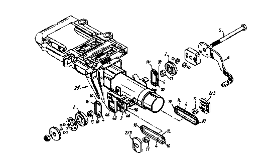
Fig. 6 is an exploded perspective view of a
construction similar to that of Fig. 4 using the
antifriction device of Fig. 1,
Fig. 7 is an exploded perspective view similar to Fig.
6 but with an antifriction device according to a second
embodiment of the invention,
Fig. 8 is a perspective view of a vertical
antifriction device according to the first embodiment of
the invention shown in Fig. 1 and used in the Fig. 6
construction,
Fig. 9 is a perspective view of a linear antifriction
device according to the first embodiment of the invention
shown in Fig. 1 and used in the Fig. 6 construction.
Fig. 10 is a perspective view of one of the
antifriction elements antifriction devices according to the
second ~mbodiment used in the construction of Fig. 7,
Figs. 11 and 12 are perspective views of vertical and
linear antifriction devices according to a third embodiment
of the invention similar to those shown in Figs. 8 and 9
for the construction of Fig. 6,
~ 0 SHEEr

CA 02204156 1997-04-30
- 3a -
Fig. 13 is a cross section taken on W of Fig. 12, and
~iD. IS i- ~ c~ ~ 7
/
DED S~IEEl

CA 022041~6 1997-04-30
WO96/15931 P~l/~b5SJ02658
In Fig. l there is shown diagrammatically an antifriction
element in the form of a slotted flanged plastics liner l
for interposition between two relatively sliding components
2,3 respectively of an adjustable steering column
construction 20, as shown in Fig. 4
The liner l has a longitudinal slot 4 providing limiting
stops through which an adjustment bar 5 of an adjustment
mechanism extends. The adjustment mechanism includes a
clamp handle 6 which when moved to the broken line position
of Fig. 4 tightens part 2 and 3 together. The liner l has
two opposing flanges 7 extending in the liners unclamped
state (Fig. 2) at an angle from the plane of a surface 8 of
the liner. When the adjustment mechanism is tightened by
the clamp handle to the position shown in Fig. 3 the liner
assists to increase the clamping action. Liner's l are
normally provided in pairs that is a vertical liner lV and
a linear liner lL (see Fig. 4). All this is as described
in our PCT Application No. PCT/GB94/01431 hereafter
referred to as "PCT application", the subject matter of
which is incorporated herein by reference.
A first improvement over the liners of the PCT application
is to provide a soft resilient block lO of an elastomeric
material either plastics or rubber at each end of slot 4.
This is shown in detail in Fig. 8 which is a vertical liner
lV and Fig. 9 which in a linear liner lL. The provision of
blocks lO cushions the impact of bolt 5 on the liner as the
column stops at the end of the vertical and/or linear
throw. In Fig. 6 which incorporates the liners of Figs. 8
and 9 rubber sleeves ll are provided to fit around bolt 5
and to slide in the liner slots 4.
A second embodiment is to provide cushioning by means of an
antifriction element formed as a stop member. This is

CA 022041~6 1997-04-30
W O 96/15931 P~l/~b55/02658
shown in Fig. 10 at 30 and in Fig. 7 where there are four
such stop members which fit into and slit within slots 4 in
antifriction elements lV' and lL' which are similar to
those shown in Figs. 8 & 9 but without cushioning blocks
10. The cushioning between the stop numbers and the
antifriction elements is by means of the stop members 30
being formed as rubber moulded parts wither solid rubber or
rubber moulded over a metal form so that the ends 31 of the
stop members have buffer portions 31. Also the stop
members have internal ribs 32 within a hole 33 in a central
boss 34 through which bolt 5 passes. The internal ribs act
to prevent rattle. These are seen in Fig. 10.
A third improvement may be seen in vertical and linear
antifriction elements lV" and lL" shown in Figs. 11 to 14.
In the liner elements shown in Figs. 11 to 14 longitudinal
walls 40 either side of longitudinal slots 4" have their
surfaces 42 provided with a slit 44 extending along most of
the length of the slots 4". Fig. 14 shows the slit 44 open
and in the uncompressed state before fitting into retaining
slots 46 in clamping mechanism brackets 48 and 50 of either
mechanism shown in Fig. 6 or Fig. 7. Fig. 3 shows the slit
44 closed under compression so that any rattle due to
manufacturing tolerances is avoided. The slit 44 can be
provided advantageously in a liner like those shown in
Figs. 8 & 9 having resilient cushion inserts 10 or in
liners without inserts 10 as shown in Fig. 7 which are
cushioned by stop members 30.
"

Representative Drawing
A single figure which represents the drawing illustrating the invention.
Administrative Status

2024-08-01:As part of the Next Generation Patents (NGP) transition, the Canadian Patents Database (CPD) now contains a more detailed Event History, which replicates the Event Log of our new back-office solution.

Please note that "Inactive:" events refers to events no longer in use in our new back-office solution.

For a clearer understanding of the status of the application/patent presented on this page, the site Disclaimer , as well as the definitions for Patent , Event History , Maintenance Fee  and Payment History  should be consulted.

Event History

Description Date
Inactive: IPC from MCD 2006-03-12
Application Not Reinstated by Deadline 2003-11-13
Time Limit for Reversal Expired 2003-11-13
Deemed Abandoned - Failure to Respond to Maintenance Fee Notice 2002-11-13
Inactive: Abandon-RFE+Late fee unpaid-Correspondence sent 2002-11-13
Letter Sent 1997-09-22
Inactive: First IPC assigned 1997-08-11
Inactive: IPC assigned 1997-08-11
Inactive: Notice - National entry - No RFE 1997-07-29
Inactive: Single transfer 1997-06-30
Inactive: Courtesy letter - Evidence 1997-06-03
Application Published (Open to Public Inspection) 1996-05-30

Abandonment History

Abandonment Date Reason Reinstatement Date
2002-11-13

Maintenance Fee

The last payment was received on 2001-10-24

Note : If the full payment has not been received on or before the date indicated, a further fee may be required which may be one of the following

  • the reinstatement fee;
  • the late payment fee; or
  • additional fee to reverse deemed expiry.

Please refer to the CIPO Patent Fees web page to see all current fee amounts.

Fee History

Fee Type Anniversary Year Due Date Paid Date
Basic national fee - standard 1997-04-30
MF (application, 2nd anniv.) - standard 02 1997-11-13 1997-04-30
Registration of a document 1997-06-30
MF (application, 3rd anniv.) - standard 03 1998-11-13 1998-10-21
MF (application, 4th anniv.) - standard 04 1999-11-15 1999-10-27
MF (application, 5th anniv.) - standard 05 2000-11-13 2000-10-24
MF (application, 6th anniv.) - standard 06 2001-11-13 2001-10-24
Owners on Record

Note: Records showing the ownership history in alphabetical order.

Current Owners on Record
THE TORRINGTON COMPANY LIMITED
Past Owners on Record
LAURENCE GEORGE HERBERT BARTON
Past Owners that do not appear in the "Owners on Record" listing will appear in other documentation within the application.
Documents

To view selected files, please enter reCAPTCHA code :


To view images, click a link in the Document Description column. To download the documents, select one or more checkboxes in the first column and then click the "Download Selected in PDF format (Zip Archive)" or the "Download Selected as Single PDF" button.

List of published and non-published patent-specific documents on the CPD .

If you have any difficulty accessing content, you can call the Client Service Centre at 1-866-997-1936 or send them an e-mail at CIPO Client Service Centre.


Document
Description 
Date
(yyyy-mm-dd) 
Number of pages   Size of Image (KB) 
Representative drawing 1997-09-10 1 20
Description 1997-04-30 6 192
Abstract 1997-04-30 1 53
Claims 1997-04-30 2 61
Drawings 1997-04-30 7 202
Cover Page 1997-09-10 1 55
Reminder of maintenance fee due 1997-07-28 1 111
Notice of National Entry 1997-07-29 1 193
Courtesy - Certificate of registration (related document(s)) 1997-09-22 1 118
Reminder - Request for Examination 2002-07-16 1 127
Courtesy - Abandonment Letter (Maintenance Fee) 2002-12-11 1 176
Courtesy - Abandonment Letter (Request for Examination) 2003-01-22 1 167
PCT 1997-04-30 11 350
Correspondence 1997-06-03 1 38