Language selection

Search

Patent 2204221 Summary

Third-party information liability

Some of the information on this Web page has been provided by external sources. The Government of Canada is not responsible for the accuracy, reliability or currency of the information supplied by external sources. Users wishing to rely upon this information should consult directly with the source of the information. Content provided by external sources is not subject to official languages, privacy and accessibility requirements.

Claims and Abstract availability

Any discrepancies in the text and image of the Claims and Abstract are due to differing posting times. Text of the Claims and Abstract are posted:

  • At the time the application is open to public inspection;
  • At the time of issue of the patent (grant).
(12) Patent: (11) CA 2204221
(54) English Title: OSCILLATING BLENDER
(54) French Title: MELANGEUR OSCILLATOIRE
Status: Expired and beyond the Period of Reversal
Bibliographic Data
(51) International Patent Classification (IPC):
  • A47J 43/046 (2006.01)
  • A47J 43/08 (2006.01)
(72) Inventors :
  • THUMA, MICHAEL C. (United States of America)
(73) Owners :
  • 24TH & DEAN
(71) Applicants :
  • 24TH & DEAN (United States of America)
(74) Agent: BORDEN LADNER GERVAIS LLP
(74) Associate agent:
(45) Issued: 2007-04-24
(22) Filed Date: 1997-05-01
(41) Open to Public Inspection: 1997-11-02
Examination requested: 2002-05-01
Availability of licence: N/A
Dedicated to the Public: N/A
(25) Language of filing: English

Patent Cooperation Treaty (PCT): No

(30) Application Priority Data:
Application No. Country/Territory Date
08/641,883 (United States of America) 1996-05-02

Abstracts

English Abstract


The present invention relates to a blender that employs mixing
blades that are capable of producing rotational mixing action and
a vertically oscillating mixing action. The invention includes
mixing blades which are in communication with a drive source for
the production of rotational movement and the use of a waveform
ramp and guide for the production of vertical mixing action.


Claims

Note: Claims are shown in the official language in which they were submitted.

THE EMBODIMENTS OF THE INVENTION IN WHICH AN EXCLUSIVE
PROPERTY OR PRIVILEGE IS CLAIMED ARE DEFINED AS FOLLOWS:
1. A mixing apparatus comprising:
a container for holding material to be mixed;
said container attachable to a transmission;
a mixing blade attachable to said transmission and disposed
within said container when said container is attached to said
transmission;
said transmission comprising a housing, power source, drive
shaft and waveform ramp;
said drive shaft connecting said power source to said mixing
blade and said waveform ramp, whereby said mixing blade and
waveform are rotated when said drive source is activated; and
said waveform ramp adapted to engage said mixing blade,
whereby said mixing blade is oscillated on a vertical axis when
said drive source is activated.
2. The device of claim 1 further comprising a second drive
shaft and guide;
said guide continuously engages said waveform ramp during the
operation of said drive source and is adapted to continuously
engage said mixing blade, whereby said mixing blade is oscillated
along a vertical axis during the operation of said drive source;
and
said second drive shaft adapted to connect said drive shaft
with said mixing blade, said second drive shaft independently
disposed within said guide, whereby said mixing blade may be
rotated and oscillated along a vertical axis at independent rates
of speed.
-7-

3. The device of claim 2 further including speed reduction
gears connecting said waveform ramp to said power source, whereby
said mixing blade is oscillated along a vertical axis at a rate
that is independent of said rotation of said mixing blade.
4. A mixing apparatus comprising:
a container for holding material to be mixed;
said container attachable to a transmission having an
attachable mixing blade that is disposed within said container when
said container is attached to said transmission;
said transmission comprising a housing, power source, drive
shaft, waveform ramp and a guide;
said drive shaft connected to said power source and said
mixing blade, whereby said mixing blade is rotated during the
activation of said power source;
said guide connected to said power source and adapted to
continuously engage said waveform ramp while being rotated by said
drive source; and
said engagement of said waveform ramp and said guide produces
vertical oscillation, whereby said mixing blade is vertically
oscillated.
5. The device of claim 4 further comprising a second drive
shaft that is disposed within said waveform ramp and is adapted to
connect said mixing blade with said drive shaft, whereby said
rotation of said mixing blade is independent of said vertical
oscillation of said mixing blade.
6. The device of claim 5 further including speed reduction
gears connecting said guide to said power source, whereby said
guide is rotated at a slower rate than said mixing blade.
-8-

Description

Note: Descriptions are shown in the official language in which they were submitted.


CA 02204221 1997-OS-O1 ,
Attorney Docket No. 21$.2
OSCILLATING BLENDER
Background of the Invention
The present invention relates generally to a food preparation
apparatus, and more particularly, to a blender that employs mixing
blades that are capable of producing a rotational mixing action and
a vertically oscillating mixing action. An electric motor acts as
the drive source and vertical oscillation is produced by a wave form
ramp that raises and lowers the mixing blades.
Suamnary of the Invention
The purpose of this invention is to provide a food preparation
apparatus that increases the mixing efficiency over that typically
associated with blenders currently available in the marketplace.
Not only does the our invention impart rotational movement to the
mixing blades, as with conventional devices, the invention also
uses a waveform ramp to vertically oscillate the mixing blades as
well.
Accordingly, an object of the present invention is to provide
a food preparation apparatus which is more efficient than those
currently available.
Another object of the present invention is to provide a food
preparation apparatus which has a vertically oscillating mixing
action.
Another object of the present invention is to provide a food
preparation apparatus which uses a waveform ramp to provide
vertical oscillation.
- 1 -

CA 02204221 1997-OS-O1
Attorney Docket No. 2182
Brief Description Of The Drawings
These and other features, objects and advantage s of the
present invention will become apparent from the following
description and drawings wherein like reference numerals represent
like elements in the several views, and in which:
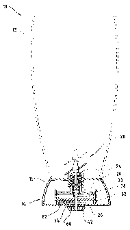
Figure 1 is a cross-sectional view of one embodiment of the
present invention; and
Figure 2 is a perspective view of the embodiment shown in
Figure 1 with portions removed to reveal aspects of the invention;
Figure 3 is an exploded view of the transmission of the
embodiment shown in Figure 1;
Figure 4 is an exploded view showing another embodiment of the
invention;
Figure 5 is an exploded cross-sectional view of the embodiment
shown in Figure 4; and
Figure 6 is an exploded view of another embodiment of the
_ invention.
Detailed Description Of The Preferred Embodiments
In accordance with a preferred embodiment of the present
invention, the food preparation apparatus, such as that shown in
Figures 1 and 2, consists of a blender 10 having a container or
pitcher 12, attachable transmission 14 having an outer housing 15,
and an electric motor (not shown). Pitcher 12 is coupled to
transmission housing 15 by attachment ring 16 formed on housing 15
which further includes a shaft seal 18 and may further use other
- 2 -

CA 02204221 1997-OS-O1
Attorney Docket No. 2182
seals to form a liquid barrier when pitcher 12 is attached. When
assembled mixing blade 20, which is attached to first shaft 22, is
located within the mixing chamber of pitcher 12.
Contained within housing 15 are the components of transmission
14 which include a pressure plate spring 24, pressure plate 26,
splined shaft connection 28, tracking guide 30, waveform ramp 32,
second shaft 34, and speed reduction gears 36. A second shaft seal
38 again provides a barrier which separates the inner comments from
the outside environment and further provides a bearing surface for
the rotation of second shaft when coupled to an electric motor via
motor attachment ring 42.
As shown in Figures 2 and 3, transmission 14 is comprised of
rotational drive system 25 that produces rotational movement which
is directly linked to the speed of the electric motor. To do this,
mixing blades 20 are directly connected to the motor by a series of
intermediate connections. First, motor attachment ring 42 is
integrally connected to second shaft 34, which is, in turn,
connected to splined shaft connector 28. The drive system is then
completed by connecting pressure plate 26 to connector 28 and to
first shaft 22 which is used to drive mixing blades 20.
To oscillate mixing blades 20 in a path parallel to drive
system 25, a waveform ramp 32 having a tracking surface 48 which
engages tracking guide 30 is used. Included on ramp 32 are a
series of depressions 31 and elevations 33 which impart vertical
movement. As ramp 32 rotates within transmission 14, guide 30
- 3 -

CA 02204221 1997-OS-O1
Attorney Docket No. 2182
tracks along surface 48, and consequently, it is raised and lowered
along a vertical axis as ramp 32 rotates. This vertical motion is
then transferred to mixing blades 20 by having guide 30 push on
pressure plate 26. As pressure plate 26 is lifted, it raises first
shaft 22 which raises mixing blades 20.
So long as guide 30 maintains contact with tracking surface
48, it may be configured in a number of ways. As shown, a waveform
configuration is used. However, two posts or rollers, or other
configurations which would be known to those of ordinary skill in
the art may also be used.
As the pressure plate 26 rises, it compresses tension spring
24 which is located between pressure plate 26 and housing 15.
Compressing spring 24 will assist in the downward movement of the
pressure plate and blades when guide 30 begins its descent down a
depression 31 on tracking surface 48. The compressive force of
spring 24 also serves to maintained the contact between guide 30
and tracking. surface 48 during all phases of movement between these
two components.
Ramp 32 is driven by speed reduction gears 36 which are
directly linked to the electric motor but at a reduced operational
speed. First gear 60 is connected to second shaft 34 and engages
second gear 62 which rotates around bearing shaft 64 located on
housing 15. Gear 62, in turn, drives ramp 32 by engaging an inner
gear ring 66 located on ramp 32.
It is important that the mixing blades maintain the ability to
- 4 -

CA 02204221 1997-OS-O1
Attorney Docket No. 2182
vertically oscillate while continuing to rotate. This may be
accomplished by the use of splined shaft connector 28 and pressure
plate 26. As shown in Figures 2 and 3, connector 28 has a fluted
outer surface 29 that is adapted to slidably fit and mate within a
correspondingly fluted internal bore 37 of pressure plate 26. Thus
configured, the mating fluted surfaces prevent rotational slippage
but at the same time allow for vertical slidability. Thus,
rotational force may be continuously applied during vertical
oscillation.
Since it is also unnecessary for guide 30 to rotate, as shown
in Figure 2, a retaining extension 70 extends from housing 15 to
secure guide 30. Guide 30 and extension 70 should be connected by
configuring the components to employ a tongue and groove or some
other slotted arrangement which would allow vertical slidability
while preventing rotational movement. Of course, these members may
be secured in other ways which those of ordinary skill in the art
would appreciate. Moreover, by having the housing act as a stop
that prevents the rotation of guide 30, it still allows for the
rotation of pressure plate 26 as was described above.
Figures 4 and 5 show another embodiment of the invention which
does not require the use of a spring. In this embodiment, which is
configured in a manner similar to that which was described above,
guide 80 includes two downwardly extending posts 82 which are
connected to waveform ramp 84 by the use of inwardly extending
portions 86 which extend into groove 88 of waveform ramp 84. In
- 5 -

CA 02204221 1997-OS-O1 -
Attorney Docket No. 2182
operation, extensions 86 travel in groove 84 during the rotation of
ramp 84. This causes guide 80 to be either pulled down or raised
up thereby vertically oscillating the mixing blade.
Figure 6 shows an alternate embodiment of the invention in
which the guide is the rotational element and the waveform ramp
remains stationary. In this embodiment, waveform ramp 90 replaces
the use of the guide and is incorporated into the device as was
indicated above with respect to guide 30. In this embodiment, it
is guide 92 that is connected to the drive means and rotates. The
vertical oscillation is thenvprovided through the use of the
waveform configuration on guide 90. These two elements may be
interconnected as was described above in either the embodiment
employing the use of a spring or the embodiment employing a tongue
and groove type arrangement as was shown in Figure 4 and 5.
While the preferred embodiments of the present invention have
been illustrated and described, it will be understood by those of
ordinary skill in the art that changes and other modifications can -
be made without departing from the invention in its broader
aspects. It is therefore intended that such changes and
modifications be covered by the following claims.
- 6 -

Representative Drawing
A single figure which represents the drawing illustrating the invention.
Administrative Status

2024-08-01:As part of the Next Generation Patents (NGP) transition, the Canadian Patents Database (CPD) now contains a more detailed Event History, which replicates the Event Log of our new back-office solution.

Please note that "Inactive:" events refers to events no longer in use in our new back-office solution.

For a clearer understanding of the status of the application/patent presented on this page, the site Disclaimer , as well as the definitions for Patent , Event History , Maintenance Fee  and Payment History  should be consulted.

Event History

Description Date
Time Limit for Reversal Expired 2010-05-03
Letter Sent 2009-05-01
Grant by Issuance 2007-04-24
Inactive: Cover page published 2007-04-23
Inactive: Final fee received 2007-02-06
Pre-grant 2007-02-06
Notice of Allowance is Issued 2006-09-14
Letter Sent 2006-09-14
Notice of Allowance is Issued 2006-09-14
Inactive: Approved for allowance (AFA) 2006-08-31
Inactive: IPC from MCD 2006-03-12
Inactive: Delete abandonment 2003-06-06
Inactive: Office letter 2003-06-06
Inactive: MF/reinstatement fee unallocated - Log 25 deleted 2003-06-06
Deemed Abandoned - Failure to Respond to Maintenance Fee Notice 2003-05-01
Inactive: Office letter 2003-03-17
Revocation of Agent Request 2003-02-25
Appointment of Agent Request 2003-02-25
Letter Sent 2002-06-13
All Requirements for Examination Determined Compliant 2002-05-01
Request for Examination Requirements Determined Compliant 2002-05-01
Request for Examination Received 2002-05-01
Inactive: Single transfer 1998-04-02
Application Published (Open to Public Inspection) 1997-11-02
Inactive: First IPC assigned 1997-08-05
Inactive: IPC assigned 1997-08-05
Inactive: Filing certificate - No RFE (English) 1997-07-28
Inactive: Courtesy letter - Evidence 1997-05-27

Abandonment History

Abandonment Date Reason Reinstatement Date
2003-05-01

Maintenance Fee

The last payment was received on 2007-02-16

Note : If the full payment has not been received on or before the date indicated, a further fee may be required which may be one of the following

  • the reinstatement fee;
  • the late payment fee; or
  • additional fee to reverse deemed expiry.

Patent fees are adjusted on the 1st of January every year. The amounts above are the current amounts if received by December 31 of the current year.
Please refer to the CIPO Patent Fees web page to see all current fee amounts.

Owners on Record

Note: Records showing the ownership history in alphabetical order.

Current Owners on Record
24TH & DEAN
Past Owners on Record
MICHAEL C. THUMA
Past Owners that do not appear in the "Owners on Record" listing will appear in other documentation within the application.
Documents

To view selected files, please enter reCAPTCHA code :


To view images, click a link in the Document Description column. To download the documents, select one or more checkboxes in the first column and then click the "Download Selected in PDF format (Zip Archive)" or the "Download Selected as Single PDF" button.

List of published and non-published patent-specific documents on the CPD .

If you have any difficulty accessing content, you can call the Client Service Centre at 1-866-997-1936 or send them an e-mail at CIPO Client Service Centre.


Document
Description 
Date
(yyyy-mm-dd) 
Number of pages   Size of Image (KB) 
Representative drawing 1998-01-25 1 5
Abstract 1997-04-30 1 12
Description 1997-04-30 6 213
Claims 1997-04-30 2 73
Drawings 1997-04-30 4 77
Representative drawing 2007-04-02 1 6
Filing Certificate (English) 1997-07-27 1 165
Request for evidence or missing transfer 1998-05-04 1 112
Courtesy - Certificate of registration (related document(s)) 1998-05-24 1 116
Reminder of maintenance fee due 1999-01-04 1 110
Reminder - Request for Examination 2002-01-02 1 117
Acknowledgement of Request for Examination 2002-06-12 1 179
Commissioner's Notice - Application Found Allowable 2006-09-13 1 161
Maintenance Fee Notice 2009-06-14 1 171
Correspondence 1997-05-26 1 27
Correspondence 2003-02-24 2 60
Correspondence 2003-03-16 1 13
Correspondence 2003-03-16 1 16
Correspondence 2003-06-05 1 13
Correspondence 2003-06-04 4 154
Correspondence 2007-02-05 1 31