Note: Descriptions are shown in the official language in which they were submitted.
CA 02204297 1997-0~-02
Field of the Invention
The present invention relates to an improved
blowout preventer valve useful in controlling and preventing
well blowouts during oil and gas well operations.
Backqround of the Invention
In the production of well fluids, e.g. oil and/or
gas, from wells situated at remote locations, for example
offshore, it has become the practice to utilize automatic
shutoff valves which are responsive to the pressure of well
fluids so as to be actuated from an open position to a
closed position in the event of loss of well fluids as may
be caused by various circumst~nce~.
During various stages of drilling, production or
servicing of an oil well, there are occasions when the
pressure in the well is sufficient to force the contents of
the well inwardly out of the well, whether the contents of
the well be oil, drilling mud, completion fluid, or the
like. A blowout preventer, or other valve device, is
therefore provided for sealing off the well during such
intervals. It may be necessary to close one or more blowout
preventers and seal off the well while a drill pipe is in
the well, while a tubing string is passing through the
casing head, or while the well and/or casing head are
otherwise empty.
Various such valves have been heretofore developed
for the purpose of automatically shutting off such a flowing
- ; CA 02204297 1997-0~-02
well, at a subsurface location in the production pipe
string. Such subsurface shutoff valves are generally held
open by fluid pressure supplied through control fluid
conduits ext~n~;ng into the well from the platform. The use
of such valves has heretofore posed problems due to the
valves being unreliable and inoperative when needed.
A more reliable means of shutoff at the mudline
was thought to involve the use of a conventional christmas
tree assembly at the subsurface. The subsurface christmas
tree had been attached to the usual subsurface wellhead
equipment and included gate valves having an actuator
automatically operable to close the gate valve in an
emergency or when desired. However, such subsurface
christmas trees were not susceptible of installation within
the well or casing extension, and therefore, were exposed to
the hostile underwater environment.
This problem was thought to be solved by a
removable subsea test tree which was adapted to be located
in a blowout preventer stack which had an upper releasable
latch assembly to permit the drill pipe or other tubular
string above the test tree to be released from the valve
portion when the latter was in a closed condition,
permitting removal of the tubular string thereabove and the
temporary abandonment of the well in the event that high
seas or inclement weather made it necessary, or desirable to
do so. More specifically in such allegedly improved
CA 02204297 1997-0~-02
structure, one or more valves were placed in an open
condition by fluid pressure pumped down a hydraulic control
line extPn~;ng from a drilling vessel to the tree disposed
in the blowout preventer stack. The hydraulic pressure
control line also extended from the drilling vessel to a
releasable connection. When pressure applied through the
line, the connection was released.
Other such valves were the automatic choke valves
that cut off flow from wells, which were often installed
intermediate the ends of the tube strings of producing
wells. When some catastrophe or failure of the controls at
the well head resulted in the well running wild, the choke
valves automatically closed the well down. Often, however,
the choke valves were destroyed or not installed and then
there was a great loss of valuable material compounded by
liability for damage caused by the pollution of the
environment by the lost material. In the use of such
automatic choke valves to the present time, a plurality of
tubing strings, one for each producing well, may be encased
in a pipe casing comprising a plurality of concentric metal
and cement casings with the tubing strings in the centre.
Ball valves have also been suggested for use as
subsurface safety valves for wells. As is known, ball
valves include a hole through the ball with a 90 degree
rotation of the ball to change from a fully opened to a
fully closed orientation.
CA 02204297 1997-0~-02
In one such ball valve developed, the ball was
more easily shifted from its closed to its open
configuration by reason of the incorporation in the valve
assembly of by-pass or equalizing valve means responsive to
the pressure of control fluid to establish communication
between the flow passage at opposite sides of the ball valve
before the ball valve is opened. In addition, the ball was
supported for rotation by means which allowed slight lost
motion between the valve and the support during the first
and last stages of ball rotation between open and closed
positions, so that the ball support was not subjected to
pressure differentials which may load the ball.
An improved such subsurface safety valve of the
ball valve type was that provided by L. L. Hudson in U.S.
Patent 3,796,257. The valve as disclosed included a ball
valve closed by well fluid pressure and opened by control
fluid pressure supplied from the surface. The subsurface
valve included a control fluid pressure responsive balancing
valve for equalizing pressure across the closed ball valve
to relieve the ball valve seating pressure. The ball valve
was rotatable by support pins and was also slightly axially
movable in its support. A sealing and operating sleeve
below the ball valve was spring loaded upwardiy. One or
more additional springs were incorporated in a production
tubing string or was removably received in a seating nipple
so as to be wireline retrievable.
CA 02204297 1997-0~-02
Yet another such valve was provided by S.S. Helmus
in U.S. Patent 3,870,101 which included one or more lower
ball valves which were pressure actuated to an open position
from the vessel or platform to permit well testing, and also
an upper latch mechanism releasable secured to the valve
portion of the assembly. Relieving of the pressure effected
closing of one or more valves, permitting the latch
~~ch~nism to be released and removed with the upper portion
of the tubing or drill pipe string to the vessel or
platform. The pistons controlling the valves were pressure
balanced, with the valves being adapted to permit reverse
flow around them when into the closed position. A pressure
actuated piston capable of forcing a lower ball valve to a
closed position was provided which, in so doing, cut a
wireline which may have parted above the assembly, and which
would otherwise hold the ball valve open.
Another valve assembly of the valve type for a
subterranean well conduit was taught in U.S. Patent
4,306,633 to R.I. Brooks which comprised a valve assembly
carriable between upper and lower portions of a tubular
conduit extendible to at least one production zone in the
well. The valve assembly comprised first and second ball
valve elements interior of the assembly and was shiftable
between fully open and fully closed positions to the fully
open position prior to the other of the valve elements being
manipulated from the fully closed position. The ball valve
, ~ CA 02204297 1997-0~-02
elements were circumferentially off-set from one another and
could be provided in a cartridge-type assembly.
While ball valves were known to perform better
with no or at least limited leakage of any flow through
pipes, since they had a substantially full bore opening
therethrough and thereby caused no substantial restriction
to flow, some problems still existed with ball valves. Such
ball valves experienced operating difficulties, particularly
when they were being opened and the well fluid pressure
below the valve which was holding the valve closed was
substantially causing a high friction loading between the
sealing faces and the surface of the ball with which they
were sealingly engaged. Indeed the operating means for
shifting the ball to an open position could in some
instances be de~loyed, thereby rendering the valve
inoperative just when it was needed to be operated.
Consequently another type of well blowout control
and prevention equipment was provided which could positively
block the entire well passage. Two types of such blowout
preventers are thus currently available for oil well blowout
prevention and control, namely, an annular preventer, and a
ram preventer.
Annular-type preventers are designed to close and
seal over an open hole, These type of preventers are also
capable of sealing around any cylindrical or nearly
cylindrical objects. These preventers have an internally
CA 02204297 1997-0~-02
reinforced rubber packing spring. The closure can be made
on drill collars, tool joints, kelly, tapered drill strings,
and the like.
Ram type preventers have twin ram closing
elements. These rams can be of the blind/shearing type
capable of closing on the drill pipe or casing. For the
latter type, two opposing "U"-shaped rams are brought
together by double-acting hydraulically controlled pistons
to close on a casing pipe or a drill string.
Typical of such ram-type blowout preventer valves
is the assembly provided in G. F. Lewis et al. U.S. Patent
3,533,468. In that patent, a well blowout preventer
assembly was provided incorporating a packer constricting
actuator which formed with the housing, at least three
pressure receiving chambers, The chamber receives control
fluid pressure acting to urge the actuator downwardly for
relieving packer constriction. The second chamber received
control fluid pressure acting to urge the actuator upwardly
for constricting the packer. The third chamber received
controllable balancing pressure acting to urge the actuator
upwardly in at least partly counterbal~nc;ng reaction to the
opposite effect of well fluid, exemplary of which would be
drilling mud, the static pressure of which (especially in
subsea oil well drilling operations) acts via the packer to
urge the actuator downwardly.
Another such valve was the stationary blowout
CA 02204297 1997-0~-02
preventer of the J. Regan U.S. Patent 3,583,480 which
included a balloon -type packing unit with a central opening
therein, and a retrievable packing insert positioned within
the opening by the engagement of a lowering with the
preventer and realeaably secured therein by hydraulically
releasable dogs latchingly engaging a latchi ng notch in an
upper ring. A central rubber portion of the packing insert
sealingly engages the pipe tool therethrough when the
packing unit is pressurized by fluid. The blowout preventer
has a fluid accumulator which absorbs the surge pressure and
excess fluid to maintain a constant pressure on the packing
insert as a pipe tool joint is stripped therethrough to
thereby maintain the sealing engagement between the insert
and the pipe.
Still another such valve is provided by G. E.
Lewis et al. in Canadian Patent 910,188. IThe patent
combines well passage constricting apparatus with a safety
valve structure. The invention provides an improvement in
well blowout prevention apparatus by the combination of
housing structure defining vertically spaced
intercommunicating chambers. An inwardly cohstrictable
packer annulus is disposed in one of such chambers for
forming therewith a vertical passage through which well
tools may be run. An annular piston is movable upwardly in
that chamber to constrict the annulus for reducing the
opening. A plug stopper having a through opening is mounted
CA 02204297 1997-0~-02
to rotate in another of the chambers to bring the through
opening into and out of registration with the pàssage. The
housing structure includes a section at the side of the plug
opposite that chamber and which is removable to provide
direct access to the plug.
Furthermore, a subsurface or mudline shutoff valve
assembly is provided by A. G. Ahistone et al. in ~n~A;an
Patent 965,697. The shutoff valve assembly, comprises gate
valves incorporated in a body which is affixed to a
~onn~ctor adapted to be run downwardly through the extension
casing and landed in the usual subsurface casing hanger.
The shutoff valve assembly has a shutoff valve or gate for
each producing zone of the well. Tubing is connected
between the shutoff valve assembly and the platform at the
top of the water to conduct production fluids to the
surface. The shutoff valves or gates are held open by
control fluid pressure supplied through control fluid
conduits from the platform. When control fluid pressure is
bled off for any reason, either purposely to shut in a
selected well zone or due to an accident or damage to the
platform or surface equipment, resulting in the loss of
control fluid pressure which can maintain the subsurface or
mudline valves open, the valves automatically c'lose.
In CAn~A;an Patent 1,239,091 issued to Bernard
Gregov et al., a blowout preventer stack, capable of
performing all the required functions, although more
CA 02204297 1997-0~-02
effectively and more economically than those of the prior
art was disclosed. The inventive feature resided in the
repl~c~ ent of ram type preventers by novel blowout
preventer valves. The valve comprises a generally
cylindrical body connectable in a riser string as a
replacement ~or a riser,the generally cylindrical body
having an access opening through one wall thereof, and being
closed by a cover plate. Two segments of a hollow sphere,
sharing a ~c -In centre of rotation are rotated towards and
away from one another between an open position where there
is free access to the borehole and a closed position where
a sealed closure is provided on the drill pipe. The
segments are adapted to rotate in opposite directions to
close downstream of the actuation site, the convex faces of
the segments facing the upward flowstream. Deleteriously,
with this arrangement, the fluid pressure tends to force the
segments apart when closure was required, thereby causing
insufficient sealing to take place.
Summary of the Invention
It is a primary objective of the present invention
to provide a blowout preventer valve functional to overcome
the problems associated with the valve of the 1,239,091
patent and harness the well fluid pressure associated with
a blowout to ensure a complete sealing of the borehole.
The improvements whereby such problems are
overcome comprise rotation of the face of the segments
CA 02204297 1997-0~-02
within the valve whereby the concave faces of said segments
are in engagement with the upstream liquid flow in
contradistinction to the teil~h;ngs of the Gregov patent
which is the exact opposite. Furthermore, the segment
travel has been increased from 45 to 60 degrees. This
results in a smaller radius ball, and a smaller overall
casing having reduced weight. The cylindrical cutout on the
inside surface of the segment has been changed to a
spherical configuration, again resulting in increased
weight. The face of the segment has been recessed whereby
it will not contact the casing during operation. A shoulder
has been added to the segment to support the seal ring and
apply uniform pressure to it when the valve is closed.
However, the most critical difference is the provision of
the segments wherein the peripheral seal is integral
therewith. Stated otherwise, the rubber seal ring has been
moved from a fixed position around the bore hole to a direct
mounting on the movable segments. Thus, the sealing is
improved due to the pressure assistance of the well fluids,
namely the seal is pressed into the body by the pressure
acting on the segment when in the closed position.
Broadly the invention comprises, in a blowout
preventer valve for connection between a riser ro~n~çtor and
a wellhead co~n~tor of a well comprising, a generally
cylindrical body connectable in a riser string said body
being provided with an access opening through an open wall
CA 02204297 1997-0~-02
thereof, two segments of a hollow sphere rotationally
mounted within said generally cylindrical body, each said
segment having a driven shaft projecting outwardly from said
generally cylindrical body; and positively actuatable means
for rotating said segments towards and away from one another
between an open position, where there is free access to the
borehole of the well, and a closed position, where a sealed
closure is provided on the drill pipe, the improvement
comprising:
sealing means associated with the periphery of said segments
and substantially integral therewith and wherein the concave
faces of said segments are functional to engage the upstream
flow of the well fluids when the valve is in the operative
position.
Description of the Drawinqs
The invention will be better understood having
reference to the description given herein and to the figures
in which:
Figure 1 is a perspective view of the blowout preventer
valve of the present invention in the closed, operative
position.
Figure 2 is a perspective view of the blowout preventer
valve of figure 1 in the open position.
Figure 3 is a plan view of the blowout preventer of
figure 1.
Figure 4 is a sectional view taken through the line A-A
!
CA 02204297 1997-0~-02
14
of the blowout preventer valve of figure 2,, namely the
valve in the open position.
Figure 5 is a sectional view taken through the line C-C
of the blowout preventer valve of figure 2, namely in
the closed position.
Figure 6 is a perspective view of a single segment.
Figure 7a is a plan view of a segment of the valve of
figure 1. Figure 7b is a base view of the segment of
figure 7a.
Description of the Preferred Embodiment
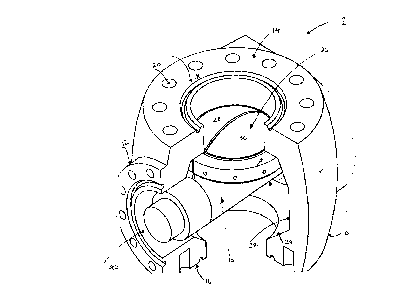
Having particular reference to figures 1 and 2 ,
there is shown the blowout preventer valve 1 comprising a
generally hollow spherical body 10 having outwardly
exte~in~ cylindrical sections 12. The body 10, on each of
its upper and lower faces 14 and 16 respectively, is
provided with a suitable internal flange 18. The flange 18
forms a plurality of circumferentially spaced apart
co~necting apertures 20 adapted to receive bolts (not shown)
whereby the blowout preventer valve 1 may be connected to
existing oil well equipment as desired.
The internal wall 22 of body 10 defines an
inwardly projecting circumferential shoulder 24 the function
of which will be described hereinafter.
Within the spherical body 10 is positioned the
valve element 26. Valve element 26 comprises a pair of
identical, hollow, quadri-spherical segments 28 and 30. By
CA 02204297 l997-0~-02
quadri-spherical is meant one quarter of a sphere. Each
segment 28 and 30 has bored shafts 32 and 34 and driven
shafts 36 and 38 respectively. The segments 28 and 30 are
interconnected whereby the driven shaft 36 and 38 of each
segment is rotatably mounted in the bored shafts 32 and 34
respectively. As a result of this arrangement, the axis of
rotation of both segments is coincident.
Shafts 32 and 34 are sealed in a pressure tight
manner at access ports 40 and 42 within the tel ; n~ 1
extensions 12 of body 10 by means of an encircling shaft
seal (not shown).
The outer faces 52 of the extensions 12 are each
provided with a suitable internal flange 54 which defines a
plurality of spaced apart apertures 56 adapted to receive
bolts (not shown) for securement of a cover plate (not
shown) over access ports 40 and 42.
The cover plates are also provided with apertures
through which the driven shafts 36 and 38 pass. Rotation of
the segments 26 and 28 is effected by rotation of the driven
shafts 36 and 38 to an angle of sixty degrees ln the open
position which in turn are connected to the output shafts of
rotary actuators. The means whereby the driven shafts are
rotated form no part of the present invention. Selection of
suitable means would be evident to one skilled in the art.
Each segment 28 and 30, as stated earlier,
comprises a forms a single piece, unitary rubber seal 60
CA 02204297 1997-0~-02
fixedly mounted around the periphery thereof thereby
becoming integral therewith. During rotation thereof each
segment 28 or 30 is functional to rotate through an angle of
approximately 60 degrees. The cylindrical cutout on the
inside surfaces of segments 28 and 30 has been altered from
the prior art cylindrically shaped cutout to thereby reduce
the weight thereof. A segment shoulder 62 is provided to
support the seal ring 60 and apply uniform pressure thereto
when the valve 1 is in the closed position. The backface 64
of the segments 28 and 30 has been moved closer to sealing
ring 60 to reduce the weight and requisite diameter of the
body 10.