Note: Descriptions are shown in the official language in which they were submitted.
CA 0220432~ 1997-0~-02
E/P Interface with Pneumatic Control
Valve for Back-up Brake Arrangement
BACKGROUND OF THE INVENTION
~ The present invention relates to a brake control system
for railroad freight cars and in particular to such a brake
control system that integrates electro-pneumatic control of
the brake with the conventional automatic pneumatic brake
control.
From the inception of the early Westinghouse air brake,
until the present time, compressed air has been employed as
the medium by which brake control signals have been
transmitted through a train of railroad freight cars, as well
as the force by which friction retardation is applied through
brake shoes that engage the car wheel treads during braking.
As the size of freight cars has increased to provide greater
load carrying capacity, and the number of cars capable of
being hauled in a train has likewise grown, there have been
continued improvements in the air brake system to make it
more efficient, in order to provide better stopping ability
consistent with the greater demands placed on the air brake
system.
Electro-pneumatic brake control systems are known to
extend the capability of the air brake beyond that which is
achieved with the conventional automatic pneumatic brake
control system presently employed. These improved
capabilities are possible due primarily to the fact that the
brake control signal can be transmitted instantaneously to
each car in the train, whereas propagation of a pneumatic
CA 0220432~ 1997-0~-02
control signal is limited to a value approaching the speed
of sound. By instantaneously transmitting a brake control
signal to each car of a train, not only is the time required
to initiate braking action on all of the cars reduced, but
in-train forces, due to disproportionate brake buildup timing
between the cars, are better controlled. This permits
greater brake force to be employed to achieve shorter stop
distance without incurring damage to car lading and couplers,
and without creating the potential for a train derailment.
The present automatic pneumatic brake control system is
fail-safe in the sense that a train break-in-two will result
in an emergency brake application on both halves of the
separated train without any initiative on the part of the
locomotive engineer. Electro-pneumatic brakes also offer the
possibility of fail-safe operation. By appropriately
configuring the electro-pneumatic valves in the brake
cylinder and exhaust piping, brake pressure is obtained in
a de-energized state. A fail-safe application of the
electro-pneumatic brakes may not be desirable, however, where
loss of power to the electro-pneumatic valves results not
from a train break-in-two, but from an electrical malfunction
on an individual car, since the brakes on such an individual
car would be applied while the train continued to run. This
could lead to thermal wheel damage, prematurely worn brake
shoes, burned brake heads and possible derailment. On the
other hand, fail-safe application of the brakes must be
provided for in the event of a power failure that affects all
of the cars, such as when a break-in-two occurs.
CA 0220432~ 1997-0~-02
SUMMARY OF THE lNv~NlION
The object of the present invention, therefore, is to
provide an electro-pneumatic brake system that operates in
conjunction with a back-up pneumatic brake system in such a
manner that the back-up pneumatic brake will become effective
to automatically override the electro-pneumatic brake when
a loss of power occurs due to a train break-in-two without
becoming effective when an individual car or cars experience
a power loss.
It is another object of the invention to integrate an
electro-pneumatic brake control with an existing railroad
freight car control valve in a manner that requires only a
m;n;mllm of modification of the control valve without
disturbing the existing pipe connections.
Still another object of the invention is to provide an
integrated pneumatic/electro-pneumatic brake control system
that maintains the existing pneumatic brake functionality and
compatibility when employed with a train having cars that may
not be equipped with electro-pneumatic controlled brakes.
In accordance with the foregoing objectives, there is
provided for a railroad freight car an integrated
pneumatic/electro-pneumatic control system in which electro-
pneumatic control means is cooperatively arranged with a
conventional railroad car control valve device, which is
normally stabilized in a release and charging position under
control of brake pipe pressure that is normally maintained
at the train running pressure to maintain the emergency
reservoir charged with supply pressure. The control valve
CA 0220432~ 1997-0~-02
manual release valve portion is replaced with a solenoid
valve portion at the release valve mounting face of a
conventional AB, ABDW, or ABDX control valve device where the
appropriate existing passages required for electro-pneumatic
control are accessed.
BRIEF DESCRIPTION OF THE DRAWINGS
These and other objects and advantages of the invention
will become apparent from the following more detailed
explanation when taken in conjunction with the accompanying
drawings in which:
Fig. 1 is an assembly view of a conventional ABD type
control valve device having a release valve portion affixed
to the control valve service portion at a mounting face
thereof where specific ports may be accessed;
Fig. 2 is a partial diagrammatic view of the control
valve device of Fig. 1 modified in accordance with the
present invention; and
Fig. 3 is a chart showing the status of application and
release solenoid valves of the electro-pneumatic brake
control of the present invention for different operating
conditions of the integrated automatic pneumatic and electro-
pneumatic brake control systems.
DESCRIPTION AND OPERATION
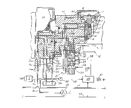
Referring to Fig. 2, there is shown an electro-pneumatic
freight car brake control system including an ABD type
control valve device 14, as is typically employed on a
CA 0220432~ 1997-0~-02
railroad freight car, modified to integrate an electro-
pneumatic brake control with the conventional automatic
pneumatic brake control in accordance with the present
invention. In addition to modified control valve device 14,
such a freight car brake control system includes a brake pipe
1, a brake cylinder 3, an auxiliary reservoir 5, an emergency
reservoir 2, and a retainer valve 10. The ends of brake pipe
1 are provided with flexible hose and couplings (not shown)
for connecting with the counterport hose and couplings of an
adjoining freight car in a freight train.
Control valve device 14 includes a mounting face 15 into
which a brake passage C and a delivery passage C1 open. Also
opening into mounting face 15 is a branch passage e5 of
emergency reservoir passage e4, and a branch passage exl of
exhaust passage ex. As shown in Fig. 1, conventional ABD,
control valves include a service portion 16 and a manual
release valve portion 17 connected to portion 16 at mounting
face 15 having the aforementioned passage openings. It is
the intent of the present invention to modify a conventional
ABD, type control valve by replacing this manual release
valve portion 17 with an electro-pneumatic valve portion 21
in order to incorporate an electro-pneumatic brake control
with the existing pneumatic brake control.
Electro-pneumatic valve portion 21 includes a normally
closed application solenoid valve 22 and a normally open
release solenoid valve 24, each having a solenoid operator
with a spring return in a two-way, two-position valve
configuration. Solenoid valve portion 21 further includes
CA 0220432~ 1997-0~-02
a supply passage 30 that connects emergency reservoir branch
passage e5 from mounting face 15 to the inlet of application
solenoid valve 22, an exhaust passage 32 that connects the
outlet of release solenoid valve 24 to exhaust branch passage
exl at mounting face 15, and a delivery passage 31 that is
interconnected between the outlet of solenoid application
valve 22 and the inlet of solenoid release valve 24. This
delivery passage 31 is connected by a branch passage and pipe
34 to one inlet of a double check valve device 35, the other
inlet of which is connected by a pipe and passage 36 to
delivery passage cl at mounting face 15. A passage c2
connects the outlet of double check valve device 35 to brake
passage c at mounting face 15.
In addition to electro-pneumatic valve portion 21, the
electro-pneumatic brake control further includes a
microprocessor unit 20 from which wires 26 and 28 are
connected to the respective solenoid operators of solenoid
application and release valves 22 and 24. A source of
electrical power such as an on-board car battery 42 is
provided to power the microprocessor and solenoid valves.
A signal wire 44 is interconnected by suitable connectors
(not shown) to a corresponding control wire of an adjoining
car (not shown) to form a trainline via which control signals
may be conducted from the locomotive to microprocessor 20.
Alternatively, signal wire 44 may be replaced by a radio
communication link via which control signals may be
transmitted to microprocessor 20. Finally, a branch pipe 3b
of brake cylinder pipe 3a is adapted to receive a transducer
CA 0220432~ 1997-0~-02
46 from which a wire 48 is connected to microprocessor 20 to
provide a feedback signal to the microprocessor corresponding
to the instantaneous brake cylinder pressure.
As is well known, brake pipe 1 is charged with
compressed air stored in the main reservoirs (not shown) of
a locomotive to a predetermined running pressure that is
established and maintained at the locomotive brake valve (not
shown) when set in release position. As is also well known,
control valve device 14 assumes a "release and charging"
position in response to the pressure in the brake pipe 1
being charged. In this ~release and charging" position, as
shown in Fig. 2, compressed air is connected from brake pipe
1 to auxiliary reservoir 5 via branch pipe and passage 5a,
passages b and b2, a passage k in slide valve 13 of the
service piston 11, a chamber Y under the service piston
diaphragm, passages al and a, and a supply passage and pipe
5a. In turn, compressed air is also conducted from chamber
Y to emergency reservoir 2 via passage n in the service
piston graduating valve 12, a passage m in slide valve 13,
passages e4, e2 and supply passage and pipe 2a. From passage
e4, the emergency reservoir air is also connected via branch
passage e5 to the supply passage 30 in solenoid valve portion
21.
Concurrently, brake cylinder device 3 is vented to
atmosphere via pipe and passage 3a, passages c, c2, the
outlet of double check valve device 35, passages 36 and cl
groove t in slide valve 13, passage ex, passage and pipe lOa,
and retAin;ng valve 10.
CA 0220432.7 1997 - 0.7 - 02
Referring to the chart of Fig. 3, solenoid valves 22,
24 are both de-energized under control of microprocessor 20
during the aforementioned ~release and charging" of control
valve device 14. The emergency reservoir supply pressure in
passage 30 is thus cut off from delivery passage 34, which
is in turn vented via release solenoid valve 24, exhaust
passages 32 and ex, passage and pipe lOa, and retainer valve
10. In this manner, the system is maintained in a charged
condition and the brakes released, irrespective of the
position of double check valve device 35.
When an electro-pneumatic brake application is desired,
a control signal is conducted over wire 44, which is
evaluated by microprocessor unit 20 in terms of the brake
cylinder pressure feedback signal received via wire 48.
Since brake cylinder pressure is exhausted during charging,
as above-explained, a difference exists between the control
and feedback signals indicative of a desired level of brake
application. Microprocessor 20 operates accordingly to
energize application solenoid valve 22 and to energize
release solenoid valve 24, as indicated in the chart of Fig.
3 for an application condition. Application valve 22 thus
shifts from its normally closed state to an open condition,
while release valve 24 shifts from its normally open position
to a closed position. Emergency reservoir pressure is thus
supplied from passage 30 to brake cylinder device 3 via
delivery passages 31, 34, double check valve device 35, brake
passages c2, c, and passage and pipe 3a.
When brake cylinder pressure, as reflected by transducer
CA 0220432~ 1997-0~-02
46, provides a feedback signal to microprocessor 20
corresponding to the signal conducted via control wire 44,
microprocessor 20 operates to de-energize application
solenoid valve 22. In its de-energized condition, valve 22
is returned to its normally closed position in which fluid
pressure commlln;cation between supply passage 30 and delivery
passage 31 is cut off, as indicated in the chart of Fig. 3
for a lap condition of the brakes.
Should brake cylinder pressure leak off and thus drop
below the desired brake application pressure, microprocessor
20 will re-establish the emergency reservoir supply path to
brake cylinder 3 in order to maintain the required pressure
until a further increase or decrease of the brake application
is desired, as reflected by a corresponding signal at wire
44.
During the time that the brakes are being applied and
released under electro-pneumatic control, brake pipe 1 is
maintained at its pre-determined running pressure and control
valve device 14 accordingly remains in its release position,
as shown, in which the emergency reservoir 2 continues to be
charged to provide an inexhaustible supply of air for the
electro-pneumatic brake control.
In the event a power failure occurs, due to a dead
battery 42, a malfunction of microprocessor 20, or a faulty
solenoid of application and release valves 22, 24, both
solenoid valves will revert to a de-energized condition,
thereby effecting a release of any brake cylinder pressure
that exists at the time. In that such a power failure
CA 0220432~ 1997-0~-02
condition would be expected to occur only on an individual
car basis, as opposed to each car of a train or even a
plurality of cars, the percentage of brake reduction would
be relatively inconsequential in terms of a train.
On the other hand, should a power loss occur due to a
train break-in-two, in consequence of which the train brake
pipe 1 breaks, each car control valve device 14 will respond
to the resultant reduction of brake pipe pressure to effect
an emergency brake application throughout both halves of the
separated train to bring the train to a safe stop. Such a
pneumatic brake control application of the brakes occurs
irrespective of the fact that the solenoid application and
release valves are arranged to fail to a brake release
condition, as heretofore explained. This is possible since
double check valve device 35 separates the automatic
pneumatic and electro-pneumatic brake controls. It will be
appreciated, therefore, that when service piston 11 of
control valves 14 on each car moves to application position
in response to an emergency reduction of brake pipe pressure,
brake cylinder delivery passage cl is cut off from exhaust
passage ex and connected to slide valve passage d. In this
manner, compressed air is supplied from auxiliary reservoir
5 to passage 36 in electro-pneumatic valve portion 21 and
thence via double check valve device 35 to brake cylinder
delivery passage c2 where it combines with the compressed air
supplied via the control valve emergency portion (not shown)
to charge brake cylinder 3 to the appropriate emergency brake
pressure. In consequence of the double check valve outlet
CA 0220432~ 1997-0~-02
being pressurized via passage 36 associated with the
automatic pneumatic brake control, passage 34 associated with
the electro-pneumatic brake control is cut off from the
double check valve outlet, thus preventing brake cylinder
pressure from exhausting via the solenoid release valve
exhaust path in the de-energized condition in which it fails.
In addition to providing automatic fail-safe emergency
back-up brake control during such power failure as occurs due
to a break-in-two, the automatic pneumatic brake control may
also be employed under manual control of brake pipe pressure,
in which case control valve device 14 is operated in
accordance with the well-known operation of ABD, ABDW and
ABDX type control valves to provide automatic pneumatic
service and emergency brake control on ~limp-in" basis. When
the automatic pneumatic brake control is thus employed, the
control signal transmitted via control wire 44 is regulated
to cause microprocessor 20 to maintain solenoid application
and release valves 22 and 24 de-energized consistent with a
release condition of the electro-pneumatic brake control.
Pressure relief valve 50 is provided to prevent an
overcharge condition of brake cylinder 3 from developing when
an emergency application occurs at the time an electro-
pneumatic application is in effect, since any air supplied
to the brake cylinder in accordance with the electro-
pneumatic application is replenished in order to maintain a
continuous source of supply air. In thus providing
inexhaustibility, however, it will be understood that full
emergency brake pressure is always available, resulting in
CA 0220432~ 1997-0~-02
excessive brake pressure when an electro-pneumatic
application is already in effect. Relief valve 50 blows off
any pressure in excess of a predetermined emergency pressure
to limit the m~X; mum brake pressure capable of being
obtained.