Language selection

Search

Patent 2204613 Summary

Third-party information liability

Some of the information on this Web page has been provided by external sources. The Government of Canada is not responsible for the accuracy, reliability or currency of the information supplied by external sources. Users wishing to rely upon this information should consult directly with the source of the information. Content provided by external sources is not subject to official languages, privacy and accessibility requirements.

Claims and Abstract availability

Any discrepancies in the text and image of the Claims and Abstract are due to differing posting times. Text of the Claims and Abstract are posted:

  • At the time the application is open to public inspection;
  • At the time of issue of the patent (grant).
(12) Patent: (11) CA 2204613
(54) English Title: A PLANT FOR CONTINUOUSLY STERILISING FLUIDS, SUCH AS MILK AND CREAM
(54) French Title: INSTALLATION DE STERILISATION CONTINUE DE FLUIDES TELS QUE LE LAIT ET LA CREME
Status: Expired and beyond the Period of Reversal
Bibliographic Data
(51) International Patent Classification (IPC):
  • A23C 3/037 (2006.01)
(72) Inventors :
  • JENSEN, JENS ANDERS (Denmark)
(73) Owners :
  • INVENSYS APV A/S
(71) Applicants :
  • APV PASILAC A/S (Denmark)
(74) Agent: MACRAE & CO.
(74) Associate agent:
(45) Issued: 2006-08-15
(86) PCT Filing Date: 1995-11-14
(87) Open to Public Inspection: 1996-05-30
Examination requested: 2002-06-05
Availability of licence: N/A
Dedicated to the Public: N/A
(25) Language of filing: English

Patent Cooperation Treaty (PCT): Yes
(86) PCT Filing Number: PCT/DK1995/000453
(87) International Publication Number: WO 1996015677
(85) National Entry: 1997-05-06

(30) Application Priority Data:
Application No. Country/Territory Date
1319/94 (Denmark) 1994-11-18

Abstracts

English Abstract


A plant for continuously sterilising fluids, such as milk and cream, comprises
a sterilising device (2) in which the fluid is sterilised
while steam is fed thereto, and a vacuum chamber (1) for removal of the water
from the fluid and from which the fluid is extracted by
means of a pump (8). The vacuum chamber (1) is accommodated before the
sterilising device (2) when seen in the flow direction of the
fluid, said vacuum chamber (1) being connected to said sterilising device (2)
through a first heat exchanger (11) for heating the fluid before
it enters said sterilising device (2).


French Abstract

Une installation de stérilisation continue de fluides tels que du lait ou de la crème comprend un dispositif de stérilisation (2) dans lequel le fluide est stérilisé pendant que de la vapeur est envoyée à l'intérieur de celui-ci, ainsi qu'une chambre à vide (1) conçue pour enlever l'eau du fluide et de laquelle le fluide est extrait au moyen d'une pompe (8). La chambre à vide (1) est disposée en amont du dispositif de stérilisation (2) par rapport au sens d'écoulement du fluide et est reliée audit dispositif de stérilisation (2) par un premier échangeur de chaleur (11) destiné à chauffer le fluide avant qu'il pénètre dans ledit dispositif de stérilisation (2).

Claims

Note: Claims are shown in the official language in which they were submitted.

7
CLAIMS:
1. A plant for continuously sterilising fluids, said plant comprising a
sterilising device,
in which the fluid is sterilised while steam is fed thereto, and a vacuum
chamber for
removing the water from the fluid and from which the fluid is extracted by
means of a
pump, characterized in that the vacuum chamber (1) is accommodated before the
sterilising device (2) when seen in the flow direction of the fluid, said
vacuum chamber
(1) being connected to said sterilising device (2) through a first heat
exchanger (11) for
heating the fluid before said fluid enters the sterilising device (2), and
that the sterilising
device is adapted to supply the fluid with an amount of water substantially
corresponding
to the amount removed by the vacuum chamber.
2. A plant as claimed in claim 1, characterized in that a homogenizer (10) is
provided between the pump (8) at the outlet (7) of the vacuum chamber (1) and
the first
heat exchanger (11).
3. A plant as claimed in claim 1 or 2, characterized in that the first heat
exchanger
(11) is adapted to heat the fluid to a temperature of from 115°C to
120°C before said
fluid is carried to the sterilising device (2).
4. A plant as claimed in claim 1, 2 or 3, characterized in that a second heat
exchanger (5) is provided before the vacuum chamber (1) when seen in the flow
direction of the fluid, said second heat exchanger heating the fluid to a
temperature from
90°C to 100°C before it is carried to the vacuum chamber (1),
and that a tube (4) is
provided between said second heat exchanger (5) and said vacuum chamber (1).
5. A plant as claimed in any one of claims 1 to 4, and where a second pump
(15)
is provided after the sterilising device (2) when seen in the flow direction
of the fluid, said
second pump sucking out the fluid from said sterilising device (2),
characterized in that
the outlet of said second pump (15) is connected to a third heat exchanger
(17, 18) for

8
cooling the fluid through a tube (16).
6. A plant as claimed in claim 5, characterized in that the third heat
exchanger (17,
18) is a twostage heat exchanger lowering the temperature of the fluid to
25°C.
7. A plant as claimed in any one of claims 1 to 6, characterized in that the
sterilising device is a steam injector.

Description

Note: Descriptions are shown in the official language in which they were submitted.


CA 02204613 1997-OS-06
WO 96/15677 PCT/DK95/00453
1
Title: A plant for continuously sterilising fluids, such as milk and cream.
Technical Field
The invention relates to a plant for continuously sterilising fluids, such as
milk and cream, said plant comprising a sterilising device, in which the
fluid is sterilised while steam is fed thereto, and a vacuum chamber for
removing tf,e water from the fluid and from which the fluid is extracted by
means of a pump.
Background Art
Inter alia AU-PS No. 610,233 discloses a plant for sterilising milk. Such a
plant is known as a direct UHT-plant (Direct ultra high Temperature Plantl.
In these plants steam is sprayed into the milk fed to the sterilising device
in such a manner that the milk is heated to a temperature of approximately
140°C. Subsequently, the milk is fed to a so-called holding chamber in
which the milk is kept for a predetermined period (approximately 2 to 15
sec) in the heated state.Then the milk is carried to a vacuum chamber
through an overflow. In this vacuum chamber the water deriving from the
steam is removed again in such a manner that the solid content of the milk
is the same when the milk leaves said vacuum chamber as before the
feeding of steam. After the processing in the vacuum chamber, the milk is
usually carried to a homogenizer and then subjected to a cooling and
packing.
Plants are also known in which the sterilising is performed by way of a
direct spraying of steam into the milk by means of a steam injector.
Such plants are relatively expensive to manufacture inter alia because the
components must be aseptic after the heat treatment in the sterilising
device. Precautionary measures must be taken everywhere in order to

CA 02204613 2005-07-21
2
meet this requirement. It is inter alia a question of expensive gaskets with
steam locks
both in the vacuum chamber and in the remaining components following the
sterilising
device, such as the pump and the homogenizes.
Brief Description of the Invention
The object of the invention is to provide a plant which is less expensive to
manufacture
than hitherto known.
The plant according to the invention is characterized in that the vacuum
chamber is
accommodated before the sterilising device when seen in the flow direction of
the fluid,
said vacuum chamber being connected to said sterilising device through a first
heat
exchanger for heating the fluid before said fluid enters the sterilising
device. The
sterilising device is adapted to supply the fluid with an amount of water
substantially
corresponding to the amount removed by the vacuum chamber.
In this manner a significant reduction of the number of components following
the
sterilising is obtained. In the vacuum chamber the water is removed from the
fluid in
question in such a manner that said fluid is further concentrated, and in the
sterilising
device this amount of water is re-added through the steam. Like in the known
plant, the
temperatures and the removal and adding of water is controlled in such a
manner that
the concentration of solid matter in the fluid in question is the same at the
outlet of the
plant as at the inlet of said plant. As the vacuum chamber and the associated
components are arranged before the sterilising device, no requirements
concerning
aseptic measures are presented to this section of the plant with the result
that the entire
plant is less expensive to manufacture than hitherto known.
According to the invention a homogenizes may be coupled between the pump at
the
outlet of the vacuum chamber and the first heat exchanger with the result that
the plant
is particularly suited for treating milk. The arranging of the homogenizes
before the
sterilising device implies further-

CA 02204613 1997-OS-06
WO 96/15677 PCT/DK95/00453
3
more that the requirement to said homogenizer being aseptic no longer
~ applies.Therefore, the homogenizer can also be manufactured relatively
inexpensive.
According to the invention the first heat exchanger may advantageously
be adapted to heat the fluid to a temperature from approximately 1 15°C
to
approximately 120°C before said fluid is carried to the sterilising
device
with the result that said sterilising device operates optimally. Correspond-
ingly, in order to ensure that a corresponding concentration of the fluid is
carried out in the vacuum chamber, a second heat exchanger may accord-
ing to the invention advantageously be arranged before said vacuum cham-
ber when seen in the flow direction of the fluid, said second heat
exchanger heating the fluid to a temperature from approximately 90°C to
approximately 100°C before said fluid enters the vacuum chamber. Fur-
thermore, a relatively long tube may be arranged between the above sec-
and heat exchanger and the vacuum chamber. This tube ensures a suitable
stay period of the fluid at the temperature in question before said fluid is
carried to the vacuum chamber. When it is a question of milk, a suitable
stabilization is here carried out of the protein content thereof. The outlet
of the sterilising device is often connected to a pump in order to ensure a
quick removal of the fluid from said sterilising device and a transfer thereof
to a holding chamber. According to the invention the outlet of this pump
may be connected to a third heat exchanger for cooling the fluid by means
of a relatively long tube serving as a holding chamber. The heat exchanger
ensures a quick cooling down again of the fluid when said fluid has stayed
in the holding chamber for a suitably short period at the high temperature
of approximately 140°C.
Finally, the third heat exchanger may according to the invention suitably
be a twostage heat exchanger lowering the temperature of the fluid to
approximately 25°C. In this manner the stages of the third heat
exchanger
can suitably be adapted to cooperate in sequence with the first and the

CA 02204613 1997-OS-06
WO 96/15677 PCT/DK95/00453
4
second heat exchanger, respectively.
Brief Description of the Drawing
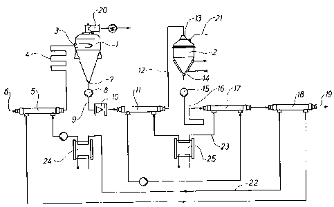
The invention is explained in greater detail below with reference to the
accompanying drawing showing a diagrammatic view of a plant for
sterilising milk or cream.
Best Mode for Carrying Out the Invention
This plant comprises a vacuum chamber 1 and a sterilising tank 2, both
parts being of a conventionally known type. The inlet 3 of the vacuum
chamber 1 is connected through a suitably long tube 4 to a heat
exchanger 5, which in turn is connected to a source with non-sterilised
milk or cream through a tube 6. The outlet 7 of the vacuum chamber is
connected to a centrifugal pump 8, the outlet of which in turn is con-
nected to a tube 9 communicating with a heat exchanger 11 through a
homogenizes 10 of a conventionally known type. This heat exchanger 1 1
is connected through a tube 12 of a suitable length to the inlet 13 of the
sterilising tank 2. The outlet 14 of the sterilising tank 2 is connected to a
centrifugal pump 15 and thereby through a tube 16 of a suitable length to
two succeeding heat exchangers 17 and 18. The latter heat exchanger 18
is through a tube 19 connected to components (not shown) for further
treatment of sterilised milk or cream.
When the plant is used for sterilising milk, non-sterilised raw milk is
carried
at a temperature of approximately 5°C through the tube 6 to the heat
exchanger 5, in which the temperature of the milk is raised to approxi-
mately 90 to 100°C. From this heat exchanger 5, the fluid flows through
the relatively long tube 4 to the vacuum chamber 1, the length of said
tube 4 being adapted in such a manner that the stay of the milk therein is
approximately 30 sec with the result that a suitable stabilisation of the

CA 02204613 1997-OS-06
WO 96/15677 PCT/DK95/00453
protein is ensured before the milk reaches the vacuum chamber 1. In the
vacuum chamber, the water is boiled off as a consequence of the drop in
pressure which the milk is subjected to therein. The temperature of the
milk drops to approximately 75°C at the outlet of the vacuum chamber 1
5 while the water steam is drained off in a conventionally known manner
through the tube 20. The resulting further concentrated milk is carried
quickly out of the vacuum chamber by means of the centrifugal pump 8
and subsequently to the homogenizer 10. Subsequently, the concentrated
milk passes through the heat exchanger 1 1, in which the temperature is
raised to approximately 115°C to approximately 120°C. From the
heat
exchanger 1 1, the milk continues through the tube 12 to the sterilising
tank 12 in which the concentrated milk is subjected to a sterilising while
directly supplied with steam through a tube 21, cf. the above AU-PS No.
610,233. In the sterilising tank 2 the milk is heated to a temperature of
approximately 140°C and then carried quickly out thereof by means of
the
centrifugal pump 15 so as to stay for a few sec. in the tube 16 before it
is carried through the heat exchangers 17 and 18. In the heat exchanger
17, the temperature is lowered to approximately 85°C, and in the heat
exchanger 18 the temperature is lowered to approximately 25°C. In the
tube 16, the centrifugal pump 15 ensures that the sterilised milk is kept at
a relatively high pressure in such a manner that possible steam is absorbed
in the milk.
The temperatures in question and the control of the vacuum chamber as
well as the sterilising tank are observed in such a manner that it is ensured
that the amount of water fed into the sterilising tank 2 is the same as the
amount of water removed in the vacuum chamber 1.
As illustrated in the drawing, the heat exchangers 15 and 18 cooperate
through a fluid circuit 22, and the heat exchangers 1 1 and 17 cooperate
through a fluid circuit 23 in such a manner that the energy used is utilized
to an optimum. Suitable heat exchangers 24 and 25, respectively, are

CA 02204613 1997-OS-06
WO 96/15677 PCT/DK95/00453
6
coupled between the above fluid circuits 22 and 23, said heat exchangers
ensuring that the necessary temperatures are maintained by means of
steam.
The invention has been described with reference to a preferred embodi-
ment. When the plant is used for treating other fluids beyond milk, such as
products for the production of dessert, cream etc., the homogenizer 10
can be omitted.
Instead of a sterilising tank 2 of the type known from AU-PS No.
610,233, it is possible to use a steam injector for spraying steam directly
into a stream of milk.
Many modifications of the plant can be carried out without thereby deviat-
ing from the scope of the invention.

Representative Drawing
A single figure which represents the drawing illustrating the invention.
Administrative Status

2024-08-01:As part of the Next Generation Patents (NGP) transition, the Canadian Patents Database (CPD) now contains a more detailed Event History, which replicates the Event Log of our new back-office solution.

Please note that "Inactive:" events refers to events no longer in use in our new back-office solution.

For a clearer understanding of the status of the application/patent presented on this page, the site Disclaimer , as well as the definitions for Patent , Event History , Maintenance Fee  and Payment History  should be consulted.

Event History

Description Date
Time Limit for Reversal Expired 2010-11-15
Letter Sent 2009-11-16
Inactive: Office letter 2007-11-02
Letter Sent 2006-08-24
Letter Sent 2006-08-21
Grant by Issuance 2006-08-15
Inactive: Cover page published 2006-08-14
Inactive: Correspondence - Transfer 2006-07-06
Inactive: Multiple transfers 2006-06-12
Pre-grant 2006-05-31
Inactive: Final fee received 2006-05-31
Notice of Allowance is Issued 2005-12-15
Letter Sent 2005-12-15
Notice of Allowance is Issued 2005-12-15
Inactive: Approved for allowance (AFA) 2005-09-13
Amendment Received - Voluntary Amendment 2005-07-21
Inactive: S.30(2) Rules - Examiner requisition 2005-02-18
Letter Sent 2004-07-27
Letter Sent 2004-04-28
Amendment Received - Voluntary Amendment 2003-02-12
Letter Sent 2002-07-24
All Requirements for Examination Determined Compliant 2002-06-05
Request for Examination Requirements Determined Compliant 2002-06-05
Request for Examination Received 2002-06-05
Letter Sent 2000-05-12
Reinstatement Requirements Deemed Compliant for All Abandonment Reasons 2000-05-03
Deemed Abandoned - Failure to Respond to Maintenance Fee Notice 1999-11-15
Letter Sent 1997-10-23
Inactive: IPC assigned 1997-08-13
Inactive: First IPC assigned 1997-08-13
Inactive: Notice - National entry - No RFE 1997-08-05
Inactive: Single transfer 1997-07-28
Application Published (Open to Public Inspection) 1996-05-30

Abandonment History

Abandonment Date Reason Reinstatement Date
1999-11-15

Maintenance Fee

The last payment was received on 2005-10-21

Note : If the full payment has not been received on or before the date indicated, a further fee may be required which may be one of the following

  • the reinstatement fee;
  • the late payment fee; or
  • additional fee to reverse deemed expiry.

Please refer to the CIPO Patent Fees web page to see all current fee amounts.

Owners on Record

Note: Records showing the ownership history in alphabetical order.

Current Owners on Record
INVENSYS APV A/S
Past Owners on Record
JENS ANDERS JENSEN
Past Owners that do not appear in the "Owners on Record" listing will appear in other documentation within the application.
Documents

To view selected files, please enter reCAPTCHA code :


To view images, click a link in the Document Description column. To download the documents, select one or more checkboxes in the first column and then click the "Download Selected in PDF format (Zip Archive)" or the "Download Selected as Single PDF" button.

List of published and non-published patent-specific documents on the CPD .

If you have any difficulty accessing content, you can call the Client Service Centre at 1-866-997-1936 or send them an e-mail at CIPO Client Service Centre.


Document
Description 
Date
(yyyy-mm-dd) 
Number of pages   Size of Image (KB) 
Representative drawing 1997-09-12 1 7
Abstract 1997-05-06 1 48
Description 1997-05-06 6 232
Drawings 1997-05-06 1 15
Claims 1997-05-06 2 52
Cover Page 1997-09-12 1 44
Description 2005-07-21 6 239
Claims 2005-07-21 2 55
Representative drawing 2006-07-13 1 9
Cover Page 2006-07-13 1 39
Reminder of maintenance fee due 1997-06-03 1 111
Notice of National Entry 1997-08-05 1 193
Courtesy - Certificate of registration (related document(s)) 1997-10-23 1 116
Courtesy - Abandonment Letter (Maintenance Fee) 1999-12-13 1 184
Notice of Reinstatement 2000-05-12 1 171
Reminder - Request for Examination 2002-07-16 1 127
Acknowledgement of Request for Examination 2002-07-24 1 193
Commissioner's Notice - Application Found Allowable 2005-12-15 1 161
Maintenance Fee Notice 2009-12-29 1 170
PCT 1997-05-06 10 295
Correspondence 1997-06-03 1 37
Fees 2000-05-03 1 36
Correspondence 2006-05-31 1 32
Correspondence 2006-08-24 5 406
Fees 2006-11-07 1 22
Correspondence 2007-11-02 1 16