Note: Descriptions are shown in the official language in which they were submitted.
CA 02205267 2003-12-16
WO 96/16859 ~ PCT/AU95I00774
METHOD OF BALANCING A HYDRAULIC VALVE FOR A POWER
STEERING GEAR
Technical Field
The present invention relates to power steering gears for motor vehicles, and
in
particular to the method of balancing hydraulic valves used in such gears.
Whilst the
invention is described in reference to rotary valves, it is anticipated that
the invention
is equally applicable to other less common styles of valves, for example
piston
valves.
Background
Known rotary valves typically employ an input-shaft which extends upwardly
from the
steering gear assembly and is connected by a flexible coupling to the steering
wheel
shaft. For this purpose, the extended end of the input-shaft is externally
splined.
The steering gear assembly is provided with a valve housing containing an
input-
shaft and a sleeve member supported thereon. For the purposes of reducing
valve
operating friction some manufacturers support the s~'eeve member on the input-
shaft
via needle roller bearings, these needle roller bearings serving to maintain a
small
radial clearance between the outside diameter of the input-shaft and inside
diameter
of the sleeve. However the vast majority of manufacturers journal the sleeve
member directly on the outside diameter of the input-shaft. For the purposes
of this
specification both these types of support will be referred to as "joumalling".
The
input-shaft extends through the sleeve and is journalled with respect to the
steering
gear driven member which, for a rack and pinion steering gear, is the pinion.
For an
°integral° steering gear box , the driven member is normally the
worm portion of a
recirculating ball nut assembly.
CA 02205267 1997-OS-13
WO 96/16859 ~ PCT/AU95100774
2
The sleeve is usually arranged to be driven in a slack free manner by a drive
pin
extending radially from the pinion although, in other less common hydraulic
valves,
this slack free drive is facilitated by the sleeve and pinion being
manufactured as an
integral arrangement. The downwardly-extending end of the input-shaft is
splined in
a loose-fitting manner to the pinion so allowing limited relative rotation
between the .
input-shaft and the pinion, and hence also between the input-shaft and the
sleeve.
Both the input-shaft and the sleeve member have respectively outwardly and
inwardly facing longitudinal chambers formed on their interFacing surfaces
which
constitute an open centre four way valve operable on relative angular rotation
of
these components.
The sleeve operates within the valve housing and is provided with several
circumferential grooves and seals which allow oil under pressure to be
directed to
and from an external hydraulic pump and to and from left and right assist
cylinders in
the manner well known in the art. The input-shaft and the sleeve are normally
biased
towards a neutral position by a torsion bar secured at its lower end to the
pinion.
The aforementioned slack-free drive of the sleeve therefore effectively means
that
the sleeve and torsion bar are rotationally connected via the pinion, the
driven
member in this case. The torsion bar is secured to the input-shaft at the
upper end of
the torsion bar, from the pinion, henceforth referred to as the "fixing end"
of the
torsion bar.
The general method of operation of such rotary valves is well known in the art
of
power steering design and so will not be described in any greater detail in
this
specification. A description of this operation is contained in US Patent
3,022,772
(Zeigler), commonly held as being the "original" patent disclosing the rotary
valve
concept.
CA 02205267 1997-OS-13
WO 96/16859 ~ PCT/AU95/00774
3
It is a requirement of operation of most steering gears that the left and
right turn
hydraulic assist characteristics be as nearly as possible identical, and this
symmetry
of operation can only be established at the time of assembly of the valve due
to the
finite tolerances assigned to the various components involved. Great accuracy
is
required in determining the neutral position of the valve components to.ensure
this
symmetry. Moreover, once this position is determined, it must be retained for
the life
of the steering gear.
For most power steering gears the theoretically ideal neutral position of the
input=
shaft and sleeve components can be defined as the position about which an
equal
angular rotation or an equal input torque applied to the input-shaft in either
direction,
with respect to the sleeve, will result in equal magnitudes of differential
pressure of
hydraulic fluid being supplied to the left and right assist cylinders during
valve
operation. The operation of determining and fixing the neutral position is
referred to
as a "balancing" operation and typically involves adjustment of the angular
disposition of the input-shaft with respect to the torsion bar whilst angular
rotation of
the input-shaft with respect to the sleeve, or alternatively the input torque
applied to
the input-shaft (which is temporarily locked to the torsion bar), is measured
against
the valve inlet pressure.
However, for a certain limited class of power steering gears, known as "centre-
take-
off' steering gears, the neutral position aimed for during balancing is not
necessarily
the position described above. These steering gears usually employ an end-
located
hydraulic cylinder, resulting in a differential operating area between right-
hand and
left-hand assist cylinders. For these centre take-off steering gears, the
neutral
position of the input-shaft and sleeve components is often shifted a small
CA 02205267 1997-OS-13
WO 96/16859 ~ PCT/AU9~I00774
4
predetermined angle either clockwise or anti-clockwise to partially compensate
for
the imbalance which would otherwise occur due to this differential operating
area.
According to the most common present practice, the fixing end of the torsion
bar is
secured to the input-shaft by a pin pressed through a diametrically disposed
hole
drilled and reamed through both components during the assembly operation which
is
performed in a "balancingn machine.
Such balancing machines take many different formats however, typically, the
driven
member (ie. the pinion or worm) and the end of the torsion bar protruding
through
the upper end of the input-shaft are both rotationally clamped such that the
torsion
bar is in its undeflected state. The input-shaft is clamped to a vernier drive
mechanism capable of imparting very fine angular displacements to the input-
shaft
relative to the driven member, and hence the sleeve. After establishing oil
supply to
the valve at required flow rate and temperature, the input-shaft is
rotationally
displaced in one direction until inlet pressure corresponds to a predetermined
check
point pressure and the corresponding magnitude of this displacement recorded.
The
input-shaft is then rotated in the opposite direction until the measured
pressure
again equals the predetermined check point pressure and a displacement
magnitude
is similarly recorded. The mean (half way point) of these two angular
displacements
is then calculated and the input-shaft rotated to this position and clamped.
The
aforementioned hole is then drilled and reamed and the pin pressed in. The
force
required to insert the pin is frequently monitored as a measure of the
interference fit
existing between the reamed hole and pin; also a "push-out" test is often
performed
to check for pin retention up to a predetermined force on the pin.
In other less common balancing machines differential pressure between the left
and
right cylinder ports of the valve, rather than inlet pressure, is used as the
criterion for
CA 02205267 1997-OS-13
WO 96/16859 ~ PCT/AU95/00774
matching check point pressure. The net effect is virtually identical since,
for most
power steering valves, differential pressure above a threshold of say 1 MPa,
corresponds very closely to inlet pressure.
In any case there are a number of disadvantages associated with the
methodology
used by such machines. Firstly, the drilling and reaming operations are.time
consuming, due to the need to provide a hole of high accuracy and good surface
finish for the subsequent interference fitting of the pin. Secondly, the
alignment of
the pin to the hole is critical for correct fitting. It frequently happens
during balancing
that, having determined the correct neutral position, the precise angular
disposition
of the input-shaft and torsion bar is disturbed due to cutting forces applied
by the
drilling or reaming operation or, indeed, the very large forces necessary for
pin
insertion. It is therefore found that, on inspection of the completed steering
gear or
valve, hydraulic operation is no longer symmetrical, requiring the valve
assembly be
extensively reworked or, alternatively, scrapped. Furthermore, it is an
undesirable
feature of the existing method that, on such precise balancing machines
involving
electronic sensing devices for both pressure and angular rotation (or in some
cases
also input torque), metal cutting operations are carried out in close
proximity to such
instrumentation.
A third disadvantage of the current hydraulic balancing methods is the
inherent
contamination of the valve components by the hydraulic fluid during balancing.
This
precludes any potentially more accurate and lower cost connection method of
the
input-shaft to the torsion bar which requires these components to be
relatively clean
and dry.
Another method of balancing a hydraulic valve for a power steering gear,
utilising air
as the balancing medium, is taught in Japanese Patent Publication No (A) 56-
CA 02205267 2003-12-16
WO 96/16859 ~ PGTIAU95I00774
6
108355 in the name of Toyota Motor Corporation. This method of air balancing
is
limited to "spool" type hydraulic valves in which the valve components have
been
pre-assembled into the valve housing of the power steering gear. This method
of air
balancing cannot be performed on valves other than the "spool" type, such as
rotary
and piston type valves which necessarily incorporate circumferential seals on
the _
outside of the sleeve for sealing hydraulic fluid. When a rotary or piston
type valve
is assembled into the valve housing of a power steering gear, air cannot be
used as
the balancing medium, as the arrangement of circumferential seals does not
provide
a sufficiently airtight seal.
A further drawback with the method of air balancing, as taught in Japanese
Patent
Publication No (A) 56-108355, is that the drilling and pinning operations for
connecting the input-shaft to the torsion bar have the same drawbacks as that
of the
known hydraulic balancing ie. that drilling, reaming and pinning is time
consuming
and can result in disturbing the angular disposition of the torsion bar and
input-shaft.
The prior art also includes a method in which balancing is achieved
mechanically
rather than hydraulically. Whilst this method allows the valve components to
be
free from oil contamination, which potentially allows for the use of adhesive
to fix
the torsion bar to the input-shaft, no detailed arrangement of how these valve
components would be connected is described.
CA 02205267 2003-12-16
WO 96/16859 ~ PGT/AU95100T74
7
Disclosure of Invention
A method of balancing an hydraulic valve for a power steering gear in which
the valve is subjected to a pressure medium, the valve comprising a sleeve
journalled on an input-shaft, the sleeve having a torsion bar connected
thereto via a driven member, the method comprising the steps of:
inserting the valve into a balance housing;
determining the neutral position of the input-shaft relative to the sleeve;
and
fixing the neutral position by rotational connection of the input-shaft and
torsion
bar, characterised in that the pressure medium used to determine the neutral
position is a gaseous medium and a temporary seating means adapted to seal the
gaseous medium is in contact with the outside surface of the sleeve during
determination of the neutral position.
Preferably the temporary sealing means is arranged to permit flow of the
gaseous
medium through at least one inlet port within the sleeve, whilst inhibiting
flow through
at least one cylinder port within the sleeve.
Preferably the temporary sealing means comprises first and second seal
portions
which contact the sleeve at a position axially on each side of an inlet groove
in which
the at least one inlet port is located.
Preferably the at least one cylinder port is located in a cylinder groove
axially
adjacent to the inlet groove. One of the seal portions contacts both sides of
the
CA 02205267 1997-OS-13
WO 96116859 PCT/A~195/00774
8
cylinder groove, thereby sealing off the cylinder groove and inhibiting flow
of the
gaseous medium through the at least one cylinder port.
Preferably the balance housing has an annular central portion located between
the
first and second seal portions of the temporary sealing means and arranged to
lie .
adjacent to the inlet groove. It is preferred that the gaseous medium is
fluidly
delivered to the inlet groove and hence admitted to the at least one inlet
port located
in the inlet groove, through a bore in the central portion.
In a first preferred embodiment of the first aspect of the present invention
at least
one of the seal portions is a hydraulically or pneumatically expandable
bladder.
Preferably the bladder is of annular form and adapted to be pressurised during
balancing, thereby inwardly expanding and sealing against the sleeve.
In a second preferred embodiment of the first aspect of the present invention
at least
one of the seal portions is an elastically deformable seal ring. Preferably
the seal
ring is adapted to be urged by an urging means and seal against the sleeve.
Preferably the urging means comprises of an actuator mechanism which is
hydraulically, pneumatically or mechanically actuated.
In a third preferred embodiment of the first aspect of the present invention
the
temporary sealing means comprises at least one cylinder probe arranged to load
radially inwardly against the at least one of the cylinder ports during
balancing and
therefore seal the at least one cylinder port. It is preferred that the
temporary
sealing means also comprises at least one inlet probe arranged to load
radially
inwardly against the at least one inlet port during balancing, permitting flow
of the
gaseous medium through the at least one inlet port.
CA 02205267 1997-OS-13
WO 96/16859 ~ PCT/AU95/00774
9
Preferably the temporary sealing means of the present invention is not a
component
of the hydraulic valve.
Preferably the hydraulic valve comprises circumferential seals solely for
sealing of
hydraulic fluid during operation of the valve. Preferably these seals are not
fitted to
the valve during balancing.
Preferably the neutral position is determined by measuring the pressure
generated
in the pressure medium for small angular rotational displacements of the input-
shaft
with respect to the sleeve, or alternatively by successively temporarily
securing the
input shaft and torsion bar and measuring the pressure generated in the
pressure
medium for input torques applied to the input shaft with respect to the driven
member.
Preferably the gaseous medium being supplied as the pressure medium during the
balancing method of the present invention is regulated to a predetermined
fixed
pressure, then passed through a fixed reference orifice before entering the
inlet of
the balance housing. Relative angular displacement of the input-shaft and
sleeve will
vary the magnitude of the restriction generated by the valve and hence vary
the gas
pressure generated at the interconnection between the fixed reference orifice
and
the balance housing. It is preferred that the gas inlet pressure to the
balance
housing is measured at the inlet to the balance housing and compared to a
check
pressure for determining the neutral position, however, it is possible that
differential
pressure of the gaseous medium between the left-hand and right-hand cylinder
ports
of the valve is also used.
CA 02205267 1997-OS-13
R'O 96/16859 ~ PCT/AU95100774
Preferably the gaseous pressure medium is air, and can be readily sourced from
a
conventional factory compressed air supply after filtering. Alternatively,
nitrogen or
some other suitable gaseous medium or combination of gases can be used.
Preferably the input-shaft and torsion bar are axially displaced with respect
to each
other prior to fixing the input-shaft to the torsion bar.
Preferably the input-shaft is connected to the torsion bar by means of a
bonding
process such as adhesive bonding, soldering, brazing, welding (eg. "electron
beam"
welding) or some other bonding agent, or mechanically keyed by means of a
plastic
or epoxy glue.
Preferably the bonding agent is injected and heated. The heating may take
place after the
bonding agent is injected to accelerate curing thereof. Alternatively, heating
may take place
during injection of the bonding or keying agent to assist in its application.
Still, alternatively,
in the case of soldering, brazing or welding, heat may be applied to
facilitate melting and
distribution of the bonding agent. In the case where the bonding process is
'electron beam'
welding, the input-shaft and torsion bar do not require an additional bonding
agent for their
connection, as the components themselves are directly heated and connected.
The bonding
agent in this case is the parent material.
The valve can be released from the balance housing when the bonding or
mechanical keying agent between the input shaft and the torsion bar has
sufficient
strength that the forces exerted during such releasing do not perturb the
fixing of the
neutral position.
After the bonding between the input shaft and the torsion bar has reached
adequate
strength, it is preferable that a substantially diametrally disposed hole is
machined
CA 02205267 1997-OS-13
WO 96/16859 . PCT/AU95/00774
11
through both these components at or near where they are bonded together and a
pin
press fitted therein. The earlier referred to disturbance of the precise
angular
disposition of the input-shaft and torsion bar will now not occur since the
cutting
forces imposed by the hole machining operation (eg. drilling or
drilling/reaming), or
indeed the loads exerted by the pressing in of the pin, is resisted by the
bonding .
medium. In these circumstances the pin constitutes a secondary safety.device
and
will only be functional in the rare circumstances that the bonding medium is
improperly applied during balancing and therefore subsequently fails during
service.
Since the pin is a secondary safety device and the precise angular disposition
of the
input-shaft and torsion bar is actually maintained by the bonding medium, it
is no
longer essential to ensure such a large degree of interference in the press-
fitting of
the pin. Consequently lower cost and more compliant pin devices can preferably
be
employed such as a roll-pin, for example a "Sel-Lok" pin as marketed by
Unbrako.
Preferably a radial clearance exists between the input-shaft and the torsion
bar and
the injected bonding agent or mechanical keying agent substantially fills the
resulting
annular cavity such as to provide a seal preventing hydraulic fluid from
leaking from
the valve in use.
In accordance with a second aspect the present invention there is disclosed a
hydraulic valve for a power steering gear, the valve comprising a sleeve
journalled on
an input-shaft, the sleeve having a torsion bar connected thereto via a driven
member,
the input-shaft having a bore, the torsion bar having a fixing end remote from
the
driven member and located within the bore of the input-shaft forming an
interface
therebetween, the bore of the input-shaft bonded to the fixing end of the
torsion bar by
a bonding agent at a position corresponding to the neutral position of the
input-shaft
relative to the sleeve, characterised in that the interface between the bore
of the input-
shaft and the fixing end of the torsion bar has at least one bond region and
at least
CA 02205267 1997-OS-13
WO 96/16859 . PCT/AU95/00774
12
one support region, the bonding agent resides in the bond region, and the
diametral
clearance between the bore of the input-shaft and the fixing end of the
torsion bar is
substantially larger in the bond region than in the support region, so that an
annular
cavity is provided for the bonding agent.
Preferably the annular cavity is of substantially constant radial depth.
Preferably in a first embodiment, the diameter of the fixing end of the
torsion bar is
smaller in the bond region than in the support region. In this embodiment the
diameter of the fixing end of the torsion bar in the bond region may be
stepped down
relative to the diameter in the support region.
Preferably in a second embodiment, the diameter of the bore of the input-shaft
is
larger in the bond region than in the support region. In this embodiment the
diameter
of the bore of the input-shaft in the bond region may be stepped up relative
to the
diameter in the support region.
Preferably the annular cavity is fully filled by the bonding agent, so as to
provide a
seal preventing oil from leaking from the valve in use.
Preferably in a further embodiment a groove exists in the fixing end of the
torsion bar
in the support region adjacent the bond region, which is adapted to hold
excess
bonding agent.
Preferably the bonding agent is an adhesive, solder, braze or weld material.
Alternatively the bonding agent may be a mechanical keying agent such as
plastic or
epoxy glue.
CA 02205267 1997-OS-13
WO 96/16859 . PCT/AU95/00774
13
The power steering gear is preferably either of the rack and pinion type with
a pinion
being the driven member, or alternatively, an integral type with a worm as the
driven
member. The hydraulic valve is preferably a rotary valve, however other types
of
valves such as piston valves can also be balanced according to the present
invention.
Description of the Drawings
A prior art valve and the present invention will now be described with
reference to
the following drawings.
Figure 1 is a sectional view of a prior art steering gear valve assembly;
Figure 2 is a partial sectional view of a first preferred embodiment of the
input-shaft
and torsion bar connection in a valve assembly according to the second aspect
of
the present invention;
Figure 3 is a perspective view of a balancing machine according to the first
aspect of
the present invention;
Figure 4 is a cross-sectional elevational view of a balance housing which
forms part
of the balancing machine depicted in Figure 3;
Figure 5 is a is a plan sectional view of the balance housing depicted in
Figure 4;
Figure 6 is a is a plan view of the linear actuator mounted on the balancing
machine
depicted in Figure 3 in an engaged position with the arm of the balance
housing;
CA 02205267 1997-OS-13
WO 96/16859 ~ PCT/AU95/00774
14
Figure 7 is a partial elevational view of the dispensing nozzle and heating
coil detail
of the bond applicating machine portion of the balancing machine in Figure 3;
Figure 8 is a partial cross-sectional view of the dispensing nozzle and
heating coil
detail of Figure 7 when the adhesive is being applied; ,
Figure 9 is a partial sectional view of a preferred embodiment of a valve
assembly
similar to Figure 2 with addition of a roll pin press fitted through a hole
diametrally
disposed through the input-shaft and torsion bar;
Figure 10 is a partial sectional view of a second preferred embodiment of the
input-
shaft and torsion bar connection in a valve assembly according to the second
aspect
of the present invention.
Figure 11 is a partial sectional view of a third preferred embodiment of the
input-
shaft and torsion bar connection in a valve assembly according to the second
aspect
of the present invention;
Figure 12 is a partial sectional view of a fourth preferred embodiment of the
input-
shaft and torsion bar connection in a valve assembly according to the second
aspect
of the present invention;
Figure 13 is a cross-sectional elevational view of a balance housing in an
alternative
embodiment to that shown in Figure 4, incorporating a bladder seal
arrangement;
Figure 14 is a cross-sectional elevational view of a balance housing in an
alternative
embodiment to that shown in Figure 4, incorporating a seal ring arrangement;
CA 02205267 1997-OS-13
WO 96/16859 . PCT/AU95/00774
Figure 15 is a cross-sectional elevational view of a balance housing in an
alternative
embodiment to that shown in Figure 4, incorporating a probe seal arrangement;
Figure 16 is a cross-sectional elevational view of an embodiment of a plastic
injection moulding nozzle used to inject plastic to form the connection of the
input-
shaft and torsion bar of a valve assembly as shown in Figure 12; and
Figure 17 is a partial sectional view of a fifth preferred embodiment of the
input-shaft
and torsion bar connection in a valve assembly according to the second aspect
of
the present invention.
.___
m~ae for ~arryng Out invention
Figure 1 schematically depicts a typical prior art valve of the rotary type.
Valve 1 is
contained in housing 3 and comprises input-shaft 2 having sleeve 4 journalled
thereon. The manner in which input-shaft 2 and sleeve 4 operate to direct oil
to and
from a hydraulic pump and assist cylinders (not shown) is well known in the
art and
will not further be described here. The lower end of input-shaft 2 is
journalled on the
lower end of torsion bar 8 via bush 6, the former axially protruding from
pinion 5.
Sleeve drive pin 7, radially protruding from pinion 5, engages a hole in
sleeve 4 to
provide a slack-free connection between sleeve 4 and pinion 5. Torsion bar 8
is firmly
connected to pinion 5 by some convenient manner such as swaging.
Torsion bar 8 and input-shaft 2 are connected by an interference fitted pin 9.
An O
ring is fitted in groove 10 on torsion bar 8 to seal hydraulic oil within the
valve 1 such
that it does not leak out between input-shaft 2 and torsion bar 8 at their
cylindrical
intertace.
CA 02205267 1997-OS-13
WO 96/16859 . PGT/AU95/00774
16
Typically, prior to connection of input-shaft 2 to torsion bar 8, input-shaft
2 must be
rotationally orientated with respect to the sleeve 4 such that the hydraulic
neutral
position of valve 1 is determined. This operation is performed in a balancing
machine where hydraulic oil is supplied to the steering gear in a manner well
understood in the art and described earlier in the "Background" to the
invention.
Once the hydraulic neutral position is determined, the drilling and reaming of
a
diametrically disposed hole through input-shaft 2 and torsion bar 8 takes
place and
pin 9 is interference fitted therein, whilst the input-shaft 2 and torsion bar
8 are
respectively held.
Figure 2 depicts a portion of a first embodiment of the second aspect of the
present
invention showing the region where input-shaft 2 connects with torsion bar 8.
In this
embodiment pin 9 of the prior art, which interconnects input-shaft 2 to the
upper
fixing end of torsion bar 8, is replaced by an adhesive bond 11 between the
respective parts at their cylindrical interface. One suitable bonding adhesive
is that
marketed under the trademark Loctite0 as Engineering Adhesive 648. Note that
the
maximum outside diameter of the fixing end of torsion bar 8, as in support
region 12,
is stepped down to a reduced diameter over bonding region 13 to facilitate the
injection of the adhesive during the fixing operation. Support region 12 will
typically
have a close clearance fit in the bore of input-shaft 2 and is aimed at
preventing the
propagation of adhesive into inner valve cavity 14. The purposely generated
radial
clearance in bonding region 13 will typically be controlled to be of the order
of 0.02 -
0.06 mm, and forms annular cavity 100 in which adhesive bond 11 resides.
Figure 10 shows a second embodiment where injection of the adhesive during the
fixing operation is facilitated by a step-up in the bore diameter of input-
shaft 2 which
again provides a controlled radial clearance over bonding region 13.
Alternatively, in
CA 02205267 1997-OS-13
WO 96/16859 . PCT/AU95/00774
17
a not shown embodiment, torsion bar 8 may also (ie simultaneously) have a step
down to a smaller diameter at its fixing end in a similar manner to the
embodiment of
Figure 2.
When utilising such a bond, groove 10 and the relevant O-ring of the prior art
valve
(as shown in Figure 1 ) may be eliminated. The adhesive utilised in the
embodiment
of the present invention also acts as a seal between input-shaft 2 and the
fixing end
of torsion bar 8 in that it fully encircles or fills the annular cavity 100
there between,
thus preventing leakage of oil from inner valve cavity 14 at the (generally)
cylindrical
intertace of input-shaft 2 and torsion bar 8.
Figure 11 shows a third embodiment similar to that shown in Figure 2, but also
includes two closely spaced together annular projections 57 and 58 on the
fixing end
of torsion bar 8, such that a circumferential groove 59 exists between them in
support region 12. Annular projection 57 acts as a dam, such that it is a
hindrance
to flow of the injected adhesive during the fixing operation. This hindrance
provided
by annular projection 57, ensures that injected adhesive substantially fills
annular
cavity 100 between input-shaft 2 and torsion bar 8 over bonding region 13.
Groove
59 is provided as an overflow receptacle for excess adhesive. Whilst it is
preferred
that the fixing operation would entail the injection of a predetermined volume
of
adhesive between the input-shaft 2 and torsion bar 8, groove 59 is provided to
ensure that where clearance between the input-shaft 2 and torsion bar 8 is
reduced
within acceptable tolerances, any excess adhesive will spill over projection
57 and
be safely retained in groove 59 during injection.
Figure 12 shows a fourth embodiment of the input-shaft/torsion bar connection,
where the fixing end of the torsion bar 8 and the adjacent bore of the input-
shaft are
respectively externally and internally splined over bonding region 13, such
that an
CA 02205267 1997-OS-13
WO 96/16859 ~ PCTIAU95/00774
18
adhesive agent or plastic can be injected between input-shaft 2 and torsian
bar 8 to
bond or mechanically key them together.
Figure 17 shows a fifth embodiment of the input-shaft/torsion bar connection,
immediately prior to bonding by soldering (or brazing), where ring 400 of pre-
fluxed-,
coated solder (or braze) material is placed in counter bore region 401 of
input-shaft 2.
An induction heating coil (described later in respect to the balancing
machine) heats
and melts ring 400 allowing the solder or braze material to distribute in
annular cavity
100 over bonding region 13.
In order for adequate bonding between torsion bar 8 and the bore of input-
shaft 2 to
take place, both parts must be relatively clean and dry before application of
the
bonding agent. The conventional method of determining the neutral position
prior to
fixing of input-shaft 2 to torsion bar 8 cannot be used as this would result
in
contamination of. these respective parts with hydraulic oil. In accordance
with the first
aspect of the present invention, air is utilised as the pressure medium in
arder to
determine the neutral position of input-shaft 2 with respect to sleeve 4. This
leaves
the parts clean and dry such that adhesive bonding, or other bonding means,
can be
used to connect them.
Figure 3 depicts one embodiment of a balancing machine in accordance with the
present invention. The balancing machine comprises rotary table 19 having
circular
inner base member 20 and an outer ring member 21 rotatably mounted thereto.
Ring
member 21 is adapted for incremental (indexed) rotation in a horizontal plane
about
base member 20, such that each balance housing 22 can be brought to one of six
stations at which various operations take place. The stations will further be
referred
to as stations A through to F. The balancing machine is adapted to balance
valves
by passing them through stations A to F in a continuous process. However, for
ease
CA 02205267 2003-12-16
WO 96/16859 ~ PGTIAU95100774
19
of description, the operation of the balancing machine will be described with
respect
to the progress of a single valve as it is followed through the various
stations.
An unbalanced valve, comprising sleeve 4, input-shaft 2, torsion bar 8 and
pinion 5
is loaded into the balancing machine at loading station A, the unbalanced
valve not.
being shown in Figure 3. The loading mechanism, also not shown, is a.robot arm
or
some other automated mechanism well known in the art.
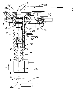
Figure 4 depicts an unbalanced valve loaded into balance housing 22 at loading
station A. Balance housing 22 comprises bore 23 with upper collet 24 and lower
collet 25 situated at opposite ends thereof. Lower collet 25 is axially
movable within
bore 23 by means of a cam mechanism which includes cam 16. Lower collet 25 is
prevented from rotation in bore 23 via sliding keylkeyway arrangement 17.
Prior to
loading of the unbalanced valve, lower collet 25 is open and ready to receive
the
unbalanced valve in an upward position, not shown in Figure 4, due to the
upward
movement of lower collet 25 in direction U as driven by cam 16, cam follower
51 and
servomotor 18. Dining loading, the unbalanced valve is inserted into bore 23
with
pinion 5 as the leading end. Pinion 5 is clamped by lower collet 25 under the
action
of pneumatic cylinder 26, and the unbalanced valve is pulled into bore 23 in a
.
direction opposite to direction U. Upper collet 24, integral with rotating
upper collet
carrier 50 and arm 28, then clamps input-shaft 2 at location 27-as shown in
Figure 5.
As shown in Figure 4, arm 28 projects upwardly and radially from collet 24 and
both
are rotatable about axis Y as part of upper collet carrier 50. Balance housing
22 has
an air inlet port 29 which allows for air to be supplied to circumferential
inlet groove
1~_of -sleeve 4 which is now held rotatably stationary within bore 23. Sealing
of inlet
groove 15 is. facilitated by standard sleeve circumferential seals 101
normally
manufactured from glass or bronze filled TeflonT"". Alternatively,
particularly if
CA 02205267 1997-OS-13
WO 96/16859 . PCT/AU95/00774
balancing is to be carried out in a low temperature operating environment
where
these standard sleeve seals 101 might not adequately conform (and hence seal)
to
bore 23, balancing may be conducted without the presence of seals 101 and a
hydraulically or pneumatically actuated expanding bladder or other more
sophisticated sealing arrangement could be employed.
Figures 13, 14 and 15 show various balance housing/sealing arrangements which
allow the unbalanced valve to be balanced using air, without the presence of
circumferential seals 101.
Figure 13 depicts an embodiment in which a balance housing 122 incorporates
temporary sealing means 160 which contacts and seals against the outside
surface of
sleeve 4 during balancing. Temporary sealing means 160 comprises first and
second
seal portions in the form of annular elastomeric expanding bladders 170 and
171
respectively, which contact sleeve 4 axially either side of inlet groove 15 in
the region
of adjacent cylinder grooves 80 and 81. Bladders 170 and 171 are each axially
sufficiently wide to contact both sides of their respective cylinder grooves
80 and 81,
thereby sealing off these cylinder grooves and hence the cylinder ports
located in
these cylinder grooves. Prior to balancing of the valve , bladders 170 and 171
are
inwardly expanded by introduction of pressurised hydraulic fluid through
Hydraulic
inlets 172 and 173 via tube 175 from a source (not shown). Bladders 170 and
171 are
housed in balance housing 122 and are spaced apart by annular central portion
188
which therefore lies adjacent to inlet groove 15 of sleeve 4. The sealing of
cylinder
grooves 80 and 81 by bladders 170 and 171 restrains air to flow to inlet
groove 15
during balancing, and hence through the inlet ports located in this inlet
groove. Air is
supplied for valve balancing from air receiver 165, filled by pumplcompressor
166 and
regulated to a predetermined fixed pressure by regulator 167. Regulator 167
also
incorporates an air filter and dryer according to normal engineering practice.
Air drawn
CA 02205267 1997-OS-13
WO 96/16859 . PCT/AU95/00774
21
from air receiver 165 passes through fixed reference orifice 168 and thence to
inlet
129 of valve balance housing 122. The pressure at inlet 129 is measured by
pressure
transducer 164. Radial bore 169 in central portion 188 communicates air to
inlet
groove 15 from inlet 129. After balancina_ bladders ~ ~n anr~ 171 ara
rlcnrcee~ ~riecrl
_ .____._~, _.____._ .. _ _.... .. . .,..., ....r.,..",w~",",
thereby unloading these bladders from the outside surface of sleeve 4, and
permitting
valve removal.
It should be noted that bladders 170 and 171 could alternatively be expanded
pneumatically, and depending on the exterior geometry of the sleeve, air to
fill these
bladders could be sourced from the same air receiver 165 from which air is
drawn for
the actual air balancing operation.
Figure 14 depicts an embodiment in which a balance housing 222 incorporates
temporary sealing means 260 which contacts and seals against the outside
surface of
sleeve 4 during balancing. Temporary sealing means 260 comprises first and
second
seal portions in the form of two seal rings 270 and 271 which contact sleeve 4
axially
either side of inlet groove 15 in the region adjacent cylinder grooves 80 and
81. Seal
rings 270 and 271 are preferably made of polyurethane or some other suitable
elastomeric material and are located against inner wall 287 of balance housing
222.
Seal rings 270 and 271 are sufficiently wide to contact both sides of their
respective
cylinder grooves 80 and 81, thereby sealing off these cylinder grooves and
hence the
cylinder ports located in these cylinder grooves. Compression rings 290 and
291 are
located axially adjacent to seal rings 270 and 271 respectively, and are
connected to
two actuator mechanisms 285 and 286. Annular central portion 288 extends
inwardly
from wall 287 between seal rings 270 and 271 and lies adjacent to inlet groove
15 of
sleeve 4. Prior to balancing of the valve, the actuator mechanisms 285 and
286, which
are preferably hydraulically or pneumatically operated from a source not
shown, are
actuated and urge compression rings 290 and 291 axially in the direction of
arrows R
CA 02205267 1997-OS-13
WO 96/16859 . PCT/AU95/00774
22
and S, respectively. As seal rings 270 and 271 are constrained by wall 287 and
central portion 288, the movement of compression rings 290 and 291 causes the
sealing surfaces of seal rings 270 and 271 to inwardly bulge and resiliently
seal
against the outside surface of sleeve 4. The sealing of cylinder grooves 80
and 81 by
seal rings 270 and 271 restrains air to flow into inlet groove 15 during
balancing and
hence through the inlet ports located in this inlet groove. Air is supplied
for valve
balancing from air receiver 165 in a similar manner to the embodiment depicted
in
Figure 13. After balancing, actuator mechanisms 285 and 286 are actuated in an
opposite direction such that compression rings 290 and 291 no longer compress
seal
rings 270 and 271, thereby unsealing these seal rings from the outside surface
of
sleeve 4, and permitting valve removal.
Figure 15 depicts a further embodiment in which balance housing 322
incorporates
temporary sealing means 360 which contacts and seals against the outside
surface of
sleeve 4 during balancing. This embodiment differs from the sealing
arrangements
depicted in Figures 13 and 14, in that temporary sealing means 360 directly
seals the
ports located within inlet groove 15 and cylinder grooves 80 and 81 on the
outside
surface of sleeve 4, rather than circumferentially sealing the grooves per se.
Temporary sealing means 360 has a plurality of inlet probes 375 and cylinder
probes
370 (only one of each is shown in Figure 15 for ease of reference). Inlet
probe 375 is
movably mounted on support member 376, such that it can be actuated,
preferably
hydraulically or pneumatically (not shown in detail), in directions shown by
arrow M,
inwardly and outwardly of balance housing 322. Likewise cylinder probe 370 is
movably mounted on support member 372 and is able to be actuated in directions
shown by arrow N, inwardly and outwardly of balance housing 322.
Prior to inserting the valve into balance housing 322, inlet probe 375 and
cylinder
probe 370 are in an outwardly retracted position to allow the valve to enter
balance
CA 02205267 1997-OS-13
WO 96/1689 - PCT/AU95/00774
23
housing 322. Once the valve is inserted, inlet probe 375 and cylinder probe
370 are
actuated to move inwardly and seal against inlet port 95 and cylinder port 96
respectively. Whilst for ease of reference only one inlet probe 375 and one
cylinder
probe 370 is shown in Figure 15, a plurality of such probes would be required.
For
instance, in a typical eight slot rotary valve there would be four inlet ports
95 within .
inlet groove 15 and four cylinder ports 96 within each of the cylinder grooves
80 and
81. In a six slot rotary valve there would be three inlet ports 95 within
inlet groove 15,
and three cylinder ports 96 in each of the cylinder grooves. In operation,
each of the
inlet probes 375 and each of the cylinder probes 370 would be actuated
simultaneously to move inwardly and seal their respective inlet ports and
cylinder-
ports. Inlet probes 375 and cylinder probes 370 would preferably have tips
made of
elastomeric material to effectively seal against inlet ports 95 and cylinder
ports 96,
respectively. Once the probes are in a sealed position, as shown in Figure 15,
air
balancing of the valve can be affected. Air is supplied to inlet port 95
through inlet
bore 379 which is located within inlet probe 375 from air receiver 165 in a
similar
manner to the embodiment depicted in Figure 13. As air must be supplied to all
inlet
probes 375 at substantially the same pressure, the air is delivered to all of
the inlet
probes 375 via an annular air distribution manifold 366. Each inlet probe 375
is fluidly
connected to air distribution manifold 366 by a flexible tube 367.
Once the valve is balanced, inlet probes 375 and cylinder probes 370 are
retracted,
thereby unsealing inlet ports 95 and cylinder ports 96 and allowing for
removal of the
valve from balance housing 322.
Whilst any one of the previously described embodiments of balance housing
could be
utilised, the method of air balancing will be further described with reference
to the
embodiment of Figures 3 and 4 showing balance housing 22.
CA 02205267 1997-OS-13
WO 96/16859 ~ PCT/AU9~/00774
24
Once loading of the unbalanced valve has taken place at loading station A,
ring
member 21 of rotary table 19 is rotatably indexed such that balance housing 22
moves to checking station B. At this station, the unbalanced valve is checked
for
correct seating within bore 23 of balance housing 22 by sensing means, not
shown,
and arm 28 and upper collet 24 are oriented about axis Y such that they are in
a
correct position for the next operation at station C. Ring member 21 rotatably
indexes so that balance housing 22 now moves to station C.
The operation performed at station C is the determination of the hydraulic
neutral
position of input-shaft 2 relative to sleeve 4. The first action that takes
place at
station C is the engagement of linear actuator 30 with arm 28. The filtered
air supply
which is connected to balance housing 22, is regulated to a predetermined
fixed
pressure and passed through a fixed reference orifice, not shown in Figure 3
but
similar to that detailed in the embodiment shown in Figure 13 , before entry
into air
inlet port 29.
As shown in Figure 3, linear actuator 30 is supported on base member 20 by two
pivotal supports 31, which are pivotal about an axis X. Linear actuator 30 is
rotatably
urgable from an unengaged position, not shown, about axis X to an engaged
position with arm 28 by extension of a pneumatic engagement actuator 32. As
seen
in Figure 6 in the engaged position, the free end of arm 28 is movably
constrained
within a V-shaped gap 33 in block 35, the latter movably mounted on a
rotatable
threaded member 36 of linear actuator 30. Rotation of threaded member 36 by a
servo motor 34, results in linear movement of block 35 which, when in the
engaged
position, rotates arm 28 and upper collet 24 about axis Y.
Once linear actuator 30 is in the engaged position with arm 28, the next step
is to
determine the neutral position of input-shaft 2 relative to sleeve 4. As
linear
CA 02205267 1997-OS-13
WO 96/16859 . PCT/AU95100774
movement of block 35 along threaded member 36 results in rotation of arm 28,
and
hence also upper collet 24 residing in upper collet carrier 50, an angular
displacement of input-shaft 2 with respect to the sleeve 4 also occurs. Input-
shaft 2
rotatably moves in clamped relationship with upper collet 24 whilst sleeve 4
is held
stationary, as it is rigidly connected to pinion 5 being held by lower collet
25.
Linear actuator 30 is connected to a control means, not shown ,which includes
an
encoder to measure angular displacement of input-shaft 2 relative to sleeve 4.
The
control means is also connected to a pressure transducer in the air supply,
not shown
in Figure 3 but similar to that detailed in the embodiment shown in Figure 13,
such
that it can measure air pressure at air inlet 29. Angular displacement of
input-shaft 2
with respect to sleeve 4, as a result of arm 28 being rotated by linear
actuator 30,
results in the measured air pressure varying. The neutral position is
determined by
displacing input-shaft 2 in one direction until the measured air pressure
corresponds
to a predetermined check pressure and the magnitude of the angular
displacement of
input shaft 2 is recorded. Input-shaft 2 is then rotated in the opposite
direction until
the measured pressure again equals the predetermined check pressure, and the
magnitude of angular displacement of input-shaft 2 in this opposite direction,
is
similarly recorded. The mean, or half way point, of these two angular
displacements is
then calculated and input-shaft 2 is rotated to this mean position, which is
the neutral
position. Upper collet 24 is then rotatably held by the clamping action of
pneumatic
brake calliper 53 on disk portion 52 of upper collet carrier 50, in order to
maintain the
neutral position prior to balance housing 22 being indexed to bonding station
D.
The previously described cam mechanism, which includes cam 16, also acts as an
oscillating mechanism. This oscillating mechanism is operated subsequent to
the
determination of the neutral position and prior to balance housing 22 being
indexed
to station D. Cam 16 imparts pure axial reciprocating movement along axis Y to
CA 02205267 1997-OS-13
WO 96/16859 . PCT/A~195/00774
26
lower collet 25, and hence to all valve components excluding input-shaft 2.
This
reciprocating axial movement substantially overcomes residual frictional
torque
existing between the fixing end of the torsion bar 8 and input-shaft 2 and
hence
ensures that torsion bar 8 is in its undeflected state prior to fixing it to
input-shaft 2.
As shown in Figure 3, a bond applicating machine 37 is positioned at bonding
station D. This station serves to bond the fixing end of torsion bar 8 in its
undeflected state to input-shaft 2. Fixing is by means of applying an adhesive
bond,
whilst input-shaft 2 is held in the neutral position relative to sleeve 4.
Bond
applicating machine 37 comprises upright support member 38 which carries a
vertically slideable carriage 39 thereon. A dispensing nozzle 40 and low
frequency
induction heating coil 41 are coaxially mounted on carriage 39. Nozzle 40 is
vertically slideable with respect to carriage 39, with heating coil 41 fixed
to carriage
39 below nozzle 40. A supply line 42 delivers adhesive from an adhesive
supply, not
shown, to nozzle 40.
When balance housing 22 is brought to bonding station D, input-shaft 2 and
torsion
bar 8 are in coaxial alignment with nozzle 40 and heating coil 41 (see Figure
7). In
order for the adhesive to be applied, carriage 39 is moved downwardly such
that
heating coil 41 surrounds input-shaft 2 near its free end, and nozzle 40 is
brought
down in sealing abutment therewith, such that the opening of nozzle 40
surrounds
the cylindrical interface of input-shaft 2 and torsion bar 8 at the free end
(see Figure
8). Adhesive is then injected such that it spreads inwardly between and around
the
cylindrical interface between input-shaft 2 and torsion bar 8, in bonding
region 13.
Nozzle 40 is then upwardly retracted and heating coil 41 is activated for a
short time,
such that it heats the upper end of input-shaft 2, the fixing end of torsion
bar 8 and
the adhesive in this vicinity. Heating assists curing of the adhesive bond.
Coil 41 is
CA 02205267 1997-OS-13
WO 96/16859 . PCT/AU95/00774
27
then also retracted upwardly. Balance housing 22 can now be indexed to curing
station E.
At curing station E the balance housing is not worked upon, and its sole
purpose is
to allow further curing of the adhesive bond assisted by retained heat in the
various,
components. Balance housing 22 is then indexed to unloading station F at which
upper collet 24 releases and lower collet 25 raises and then releases the
balanced
valve, which is then removed from the balancing machine by the robot arm or
automated mechanism (not shown).
Once removed from the balancing machine, the balanced valve may be placed
aside
for further curing of the adhesive bond
When bonding has reached sufficient strength, balanced valve 1 is taken to a
separate work station where a substantially diametrally disposed hole is
machined
through input-shaft 2 and the fixing end of torsion bar 8, preferably at or
near where
they are bonded together. Pin 55 as shown in Figure 9 can then be press fitted
therein. Pin 55 is a roll-pin and need not have the same degree of
interference fit as
required in the case of prior art pin 9. Principally, pin 55 is a safety
device and may
only be functional in the rare circumstance where the bond may fail during
service of
the valve.
In further embodiments not shown, the method of the present invention may vary
in
the steps performed and the apparatus to perform this method, resulting in the
balancing machine having a different configuration.
CA 02205267 1997-OS-13
WO 96/16859 ~ PCTIA1T95/00774
28
For instance, in not shown embodiments, the adhesive bond between input-shaft
2
and the fixing end of torsion bar 8 may be replaced by a soldered, brazed or
welded
joint (such as that achieved by "electron beam" welding).
In an embodiment as earlier described with reference to Figure 12, where the
adhesive bond between input-shaft 2 and the fixing end of torsion bar 8 is
replaced
by a mechanical keying agent such as plastic, the bonding station D in the
earlier
described embodiment of the balancing machine would be replaced by a plastic
injection moulding station. Such a moulding station, may in one embodiment
incorporate an injection nozzle 97, as shown in Figure 16, which is adapted to
fit
over the free end of input-shaft 2. Nozzle 97 having a bore 98 through which
the
plastic is delivered to the cavity between input-shaft 2 and the fixing end of
torsion
bar 8. The plastic is supplied to the nozzle 97 by a typical screw feeder 99,
shown
schematically.
In other, not shown, embodiments the balancing machine previously described
may
differ in the number of work stations and the operations performed. For
instance, in
one variation, the loading station A and unloading station F of the described
embodiment could be combined into a single station, where loading of an
unbalanced valve into balance housing 22 occurs after a balanced valve is
removed.
In another not shown embodiment the curing station E may not be required
depending on the cycle time of the various operations and the curing time for
the
adhesive bond.
Alternatively, at the expense of a longer cycle time for the process, stations
A to F
(or subsets thereof ) could be combined as a single, multifunctional station.
CA 02205267 1997-OS-13
WO 96/16859 ~ PCT/AU95/00774
29
In further not shown embodiments the balance housing/sealing arrangements may
incorporate seal arrangements which differ in shape and configuration to those
shown in Figures 13, 14 and 15. It should also be understood that a
combination of
the various seal elements such as bladders, ring seals and probes could be
utilised
in a not shown single embodiment of a balance housing/sealing arrangement.
It will also be appreciated by those skilled in the art that the balancing
method
disclosed in this specification could be equally applied to "reverse"
balancing
machine formats, where the input-shaft is rotationally held fixed and the
driven
member (and hence also the sleeve) rotated during determination of the neutral
position. In such a balancing machine the balance housing, and associated
temporary sealing means, would be preferably allowed to rotationally float so
that
sealing on the outside surtace of the sleeve is not interrupted as the driven
member
is rotated. Also, in this configuration of balancing machine, the
aforementioned axial
reciprocating movement applied to all valve components excluding the input-
shaft
could be accommodated if the balance housing is additionally able to axially
float,
again in order that sealing on the outside surface of the sleeve is not
interrupted.
Alternatively, the axial reciprocating movement could be applied to the input-
shaft
and a keying arrangement employed to ensure that no rotational motion of this
component occurs.
It should also be understood that balancing a valve by means of a gaseous
pressure
medium such as air, may also be achieved by passing the air through the valve
in a
reverse direction to that shown in the embodiments. This would result in air
exiting
from the valve through ports in the sleeve.
It should be obvious to persons skilled in the art that numerous variations
and
modifications could be made to the method and apparatus of the present
invention
CA 02205267 1997-OS-13
WO 96/16859 - ~ PGT/AU95/00774
as described and with reference to the drawings without departing from the
overall
spirit and scope of the invention.