Note: Descriptions are shown in the official language in which they were submitted.
CA 0220~289 1997-0~-13
~ . - 2 -
1 ~ TITLE: IRRIGATION ASSEMBLY FOR POTTED PLANTS
2 BACKGROUND OF THE INVENTION
3 The present invention relates to an irrigation
4 assembly for potted plants and more particularly, to an
irrigation assembly for timely supplying the water
6 automatically to prevent the potted plants from being
7 subjected to inadequate or irregular supplies of water.
8 The keeping of potted plants in homes has been
9 very popular for a long time but problems often occur
in the maintenance of those plants. For example,
11 different plants have different needs in the supply of
12 water and it is not always easy for an owner to
13 remember on which days certain plants should be watered
14 to keep them in the best condition. Furthermore, if an
owner is away from for a long period of time the plants
16 ~ will suffer from a lack of water. Alternatively, the
17 plants may be exposed to inappropriate watering by a
18 person such as a neighbor, who may not be familiar with
19 all the different watering needs involved. Thus, there
is a long unfulfilled need for an irrigation assembly
21 which can automatically supply the exact amount of
22 water at the desired intervals. The present invention
23 provides a solution based on the limitations described
24 above.
It is a primary object of the present invention to
26 provide an irrigation assembly for potted plants which
27 can proceed timely water supplying automatically to
28 prevent the potted plants from being exposed to
29 _ _
CA 0220~289 1997-0~-13
l inappropriate supplies of water.
2 In accordance with one aspect of the invention,
3 there is provided an irrigation assembly for potted
4 plants which can timely supply water automatically to
the potted plants and can be set in a fixed-humidity
6 mode or in a fixed-amount mode based on the features of
7 the potted plants. In a fixed-humidity state, the
8 humidity of the soil can be detected through a humidity
9 sensing rod inserted into the soil and then, the
detected humidity value is compared with a
11 predetermined humidity upper limit/lower limit value.
12 The irrigation assembly supplies water in an
13 insufficient humidity condition of the soil and the
14 predetermined humidity value is set to adjust the
humidity with reference to various plants.
16 In accordance with another aspect of the
17 invention, there is provided an irrigation assembly for
18 potted plants which is in a fixed-amount state. The
19 time between watering days and the amount of the water
supplied every time can be set through rotary switches
21 on a control panel to suit the different requirements
22 of plants. Between the fixed-humidity mode and the
23 fixed-amount mode, the control circuit does not need to
24 be changed, it only requires to switch by an internal
switch.
26 In accordance with still another aspect of the
27 invention, there is provided an irrigation assembly for
28 potted plants in which a test key and an indicator
29
-
CA 0220~289 1997-0~-13
- 4 -
1 light are installed on the control panel for
2 respectively testing whether the irrigation assembly
3 operates normally and further providing an on-off
4 indication every other fixed time.
In accordance with yet another aspect of the
6 invention, there is provided an irrigation assembly for
7 potted plants with a convenient design in the housing
8 thereof. A control circuit PCB is designed to be a
9 control panel type in which the rotary switches are
installed on a front surface thereof and the control
11 circuit is formed on a rear surface thereof.
12 Furthermore, the control circuit PCB permits easy
13 access to batteries therein for easy replacement
14 thereof.
In accordance with yet still another aspect of the
16 invention, there is provided an irrigation assembly for
17 potted plants in which the humidity sensing rod is
18 formed as a long strip where a long strip carbon film
19 and a plurality of spaced separate carbon films are
formed on respective surfaces thereon. Each separate
21 carbon film is in a series connection with a respective
22 first end of one of a plurality of resistors and a
23 respective second end of each of the resistors is
24 connected in parallel to form a single electrode. This
electrode and another electrode formed by the long
26 strip carbon film described above are simultaneously
27 connected to the control circuit PCB. The humidity
28 values at different positions are detected by inserting
29
CA 0220~289 l997-0~-l3
-- 5
1 the humidity sensing rod into the soil whereby the
2 control circuit determines the humidity of the soil
3 through an RC transfer circuit after the amount of the
4 water contained in the soil is detected by the humidity
sensing rod with the above-described double-sided
6 carbon films and then converted to a soil impedance
7 value. Additionally, the components of this assembly
8 are inexpensive to buy and maintain. Thus, in addition
9 to achieving advantages of automatically controlling
the humidity and low cost, the double-sided carbon
11 films of the long strip shaped humidity sensing rod can
12 prevent oxidization or corrosion to provide a longer
13 lifetime in usability. Furthermore, the design of the
14 humidity sensing rod in a long strip form provides for
detecting all of the humidity values in different
16 positions, whether high or low, in the soil at the same
17 time. Therefore, the present invention is superior to
18 the conventional particle shaped semiconductor humidity
19 sensing device which has the limitation of detecting a
single-point area only and provides a stable and
21 remarkable design in detecting humidity.
22 The above objective, other features and advantages
23 of the present invention will become more apparent by
24 describing in detail the preferred embodiments thereof
with reference to the attached drawings, in which:
26 Flg. 1 is an exploded view of an irrigation
27 assembly in accordance with the present invention;
28 Fig. 2 is an expanded sectional view of the
29
CA 0220~289 1997-0~-13
- 6 --
1 housing in connection with a water pump of an
2 irrigation-assembly in accordance with the present
3 invention;
4 Fig. 3 is a plan view of the control circuit-
printed circuit board of an irrigation assembly in
6 accordance with the present invention;
7 Fig. 4 is a preferred embodiment of the present
8 invention;
9 Fig. 5 is a structural diagram of the water outlet
device of an irrigation assembly in accordance with the
11 present invention;
12 Fig. 6 schematically shows the carbon films on the
13 front and rear surfaces of the humidity sensing rod in
14 accordance with the present invention;
Figs. 7 and 8 are schematic diagrams of the fixed-
16 humidity mode and the fixed-amount mode control panels
17 in accordance with the present invention; and
18 Fig. 9 shows a block diagram of the control
19 circuit in accordance with the present invention.
As shown in Fig. 1, an irrigation assembly in
21 accordance with the present invention includes a
22 housing 10 with a motor case 11 and a battery case 13
23 installed therein for coupling with a motor 14 and
24 receiving batteries 131. A water pump 20 extends
downwardly from a bottom side of the housing 10. A
26 water outlet device 50 and a humidity sensing rod 60
27 are respectively connected to a water discharge pipe 52
28 and a waterproof cable 64 extending outwardly from one
29
CA 0220~289 1997-0~-13
side of the housing 10. A bottom printed circuit board
2(PCB) 15 with a motor driving circuit formed thereon is
3linked with and positioned above the motor 14. Each of
4a pair of pivot holes 17 is defined in an upper portion
5of a respective one of two opposed sides of the housing
610. A control circuit PCB 30 includes two rotary
7switches 34, 35, a test key 36 and an indicator light
837. Each of a pair of clips 31 is respectively secured
9to one of the two opposed sides of the control circuit
10PCB 30. Each clip 31 has a stub 32 extending from an
11end face thereof and each stub 32 is pivotally received
12in a respective one of the pivot holes 17, whereby the
13control circuit PCB 30 is pivotally received in the
14housing 10 and access to the batteries 131 is
15accordingly possible, as shown in Fig. 3. A plurality
16of spring blades 12 are formed in the battery case 13
17of the housing 10 and extend upwardly for providing
18position confinement when the circuit control PCB 30 is
19disposed within the housing 10. A plurality of contact
20points on a bottom surface of the control circuit PCB
2130 correspond to the positions where the batteries
22located so that the electric power of the batteries 131
23~ is directly supplied to the control circuit PCB 30
24without requiring connections through electric wires.
25An application specific integrated circuit ~ASIC)
26central processing unit (CPU) of a surface-mount type
27forming a control loop is provided to decide whether
28the motor 14 is turned on or turned off and the motor
29
CA 0220~289 l997-0~-l3
-- 8
1 running time is long or short. Alternatively, the
2 pumping ope~ation and operating time of the water pump
3 20 are determined depending on the comparison between
4 the setting states of the two rotary switches 34, 35.
The water pump 20 on the left side of the Fig. 1
6 includes a shaft sleeve 21 through which a driving
7 shaft 22 extends therein and a plurality of positioning
8 bushes 23 mounted around the shaft 22, a water conduit
9 27, a water-pumping plate 24, a bottom cap 25 and a set
of motor blades 26. A top end of the driving shaft 22
11 in the shaft sleeve 21 iS connected to a rotary shaft
12 of the motor 14 and a bottom end thereof is connected
13 to the set of motor blades 26. A top end and a bottom
14 end of the shaft sleeve 21 are respectively connected
to the housing 10 and the water-pumping plate 24 while
16 the set of motor blades 26 iS positioned between the
17 water-pumping plate 24 and the bottom cap 25. A bottom
18 end of the water conduit 27 iS connected to one side of
19 the water-pumping plate 24 and a top end thereof is
connected to the water discharge pipe 52 through a
21 water conducting chamber 16 formed in a corner side on
22 the bottom surface of the housing 10, as shown in Fig.
23 2. In this configuration, water is pumped into the
24 water discharge pipe 52 as a result of the turning of
the set of motor blades 26 of the water pump 20 after
26 the motor 14 has been turned on.
27 Fig. 2 shows an assembly of the priorly-mentioned
28 components. Referring to Figs. 1 and 2, a waterproof
29
CA 0220~289 l997-0~-l3
cover 40 with a transparent observation hole 41
2 prevents water from leaking into the irrigation
3 assembly.
4 The detailed constructions of the water outlet
device 50 and the humidity sensing rod 60 are shown in
6 Fig. 5 and Fig. 6 respectively. With reference to Fig.
7 5, a lower portion of the water outlet device 50 iS
8 connected to a spike 51 by mutual coupling. A passage
9 502 extends from a top of the water outlet device 50 to
the lower portion thereof and communicates with a
11 plurality of outlets 501. Fig. 6 shows a front side and
12 a rear side of the humidity sensing rod 60, in which
13 carbon films are in a long strip first form 61 and in a
14 second form of separate strips 62 spaced apart from
each other. The long strip of carbon film 61 and the
16 separate strips of carbon films 62 are respectively
17 formed on the surfaces of the front side and the rear
18 side thereof. Each separate carbon film 62 has an
19 internal copper foil extending to a fixed base 601
respectively and in a series connection with a resistor
21 63 thereln individually, and then connects in parallel
22 to form a single electrode extending outwardly.
23 Therefore, there is an output signal produced between
24 the single electrode described above and another
electrode formed by the long strip shaped carbon film
26 61. A function of the humidity sensing rod 60 iS that
27 different impedances are formed on the carbon films of
28 the front side surface and the rear side surface
29
CA 0220~289 i997-0~-l3
- 10 -
1 thereof through the impedances generated by the water
2 contained in the soil. The separate carbon films 62 at
3 different positions are provided for detecting the
4 impedance values of the water contained in various soil
locations, thereby the output impedance is inversely
6 changed with the soil humidity so that the moisture of
7 the soil can be detected.
8 The humidity sensing rod 60 described above also
9 simultaneously detects the moisture of the soil in
different~depths which prevents oxidization or
11 corrosion due to water invasion from adopting the
12 design of using the carbon films to provide a longer
13 lifetime in usability.
14 The block diagram of the control circuit of the
present invention, as shown in Fig. 9, is composed of a
16 single-chip microprocessor 71, a mode-switching switch
17 711, a water-supplying test and indication device 72,
18 an upper limit setting element 73, a lower limit
19 setting element 74, a power supply 75, a voltage
regulator 76, a water-pumping motor and driver 77, a
21 . time-base generator 78, an RC transfer circuit 79 and a
22 humidity sensing rod 60. The upper limit setting
23 ele=ment 73 and the lower limit setting element 74,
24 which are a plurality of selection contacts formed by
the two aforenamed rotary switches 34, 35, are
26 connected to the single-chip microprocessor 71. The RC
27 transfer circuit 79 which is made up of resistors and
28 capacitors is connected to an output terminal of the
29
CA 0220~289 1997-0~-13
-- 11 --
1 humidity sensing rod 60. This RC transfer circuit 79
2 can be charged responsive to the impedance indicated by
3 the humidity sensing rod 60. The humidity of the soil
4 is determined based on a relative relation between the
time required to charge the capacitors to a
6 predetermined value and the moisture of the soil. The
7 operation of the water-pumping motor and driver 77 is
8 controlled by the output of the single-chip
9 microprocessor 71. The mode-switching switch 711 on one
side of the single~chip microprocessor 71 serves as a
11 switch between the fixed-humidity mode and the fixed-
12 amount mode.
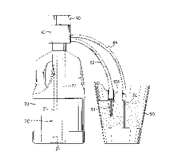
13 In a practical application with reference to Fig.
14 4, the water pump 20 of the housing 10 can be inserted
into a general container.70 and the like. The spike 51
16 of the water outlet device 50 and humidity sensing rod
17 60 are inserted into soil of the pot 80. A distal end
18 portion of the humidity sensing rod 60 is completely
19 inserted into the soil to provide an accurate humidity
measurement of the soil. The outlets 501 of the water
21 outlet device 50 are disposed slightly above a top
22 surface of the soil in the pot 80.
23 In the circumstance described above, the aforesaid
24 control circuit PCB 30 is set in a fixed-humidity mode,
as shown in a control panel as shown in Fig. 7. The
26 upper limit value and the lower limit value of the
27 humidity are set by means of the two rotary switches
28 34, 35 respectively. When the humidity sensing rod 60
29
CA 0220~289 1997-0~-13
- 12 -
1 detects the moisture of the soil is not enough, the
2 water outlet device 50 automatically receives pumped
3 water from the container 70 and supplies the water
4 through the water outlet device 50 to moisturize the
soil after a delay of time. The above-described
6 operation proceeds until the humidity of the soil
7 increases to meet the set value. In the same way, when
8 the moisture of the soil is too high, the operation of
9 supplying water is halted temporarily. Thus, the
moisture status of the soil is maintained the same as
11 the set value by repeatedly detecting the moisture
12 status of the soil. The test key 36 on the upper side
13 of the control panel is adapted to determine whether
14 the control circuit PCB 30 is in a normal operation
state and the indicator light 37 thereof is adapted to
16 determine whether the indicator light 37 turns on/off
17 once whenever the detecting operation proceeds.
18 If the aforementioned control circuit PCB 30 is
19 set to be in a fixed-amount mode, as shown in a control
panel as shown in Fig. 8, the humidity sensing rod 60
21 can be removed without having any effect. In this
22 fixed-amount mode, the time between two separate day
23 for supplying water and the amount of the water used
24 for supplying are respectively set by means of the two
rotary switches 34, 35, and the control circuit PCB 30
26 performs a fixed-time turning on/off operation
27 according to the predetermined state so that the potted
28 plants are watered at a fixed time and in a fixed
29
CA 0220~289 1997-0~-13
1 amount.
2 Regarding a method for operating in the fixed-
3 humidity mode, the irrigation assembly detects the
4 amount of the water contained in the soil every other
six minutes after being powered on to prevent
6 misoperation and energy saving. If the soil is too dry
7 after comparing with a predetermined humidity value,
8 the a-ssembly pumps the water for two seconds (about 20
g ml), counts the number of times the water is pumped and
determines whether the number is greater than 15. This
11 step primarily prevents the container from running out
12 of water and thereby detects an abnormal situation
13 happened such that it directly passes to the next step
14 after the indicator light has flashed twice. If the
soil is too wet after comparing with the predetermined
16 humidity value, operation of the watering assembly is
17 delayed for 60 minutes, and then, the amount of the
18 water contained in the soil is determined again-since
19 the speed of evaporating the water is rather slow under
the condition of containing too much water in the soil,
21 and compared with a dry value subsequently. The
22 humidity of the soil is controlled to be maintained at
23 a predetermined value in accordance with the recycling
24 operation.
As to a method for operating in the fixed-amount
26 mode, after being powered on, the irrigation assembly
27 reads a predetermined interval value set on a rotary
28 switch and set the accumulated number of times to be
29
CA 0220~289 1997-0~-13
~ - 14 -
1 zero and then, accumulates the interval and reads the
2 accumulated- interval. This accumulated interval value
3 is compared with the previously accumulated interval
4 = value and is then compared with the predetermined
interval value to see if they are the same. If the
6 rotary~ switch has been turned to adjust the time, the
7 above counting is renewed. If the rotary switch has not
8 been turned for that adjustment, then the water-pumping
g motor operates the water pump to supply water at a
fixed amount. Thereafter, the accumulated time value is
11 set to be zero and the steps described above are
12 repeated after the amount of water to be used has been
13 supplied.
14 Accordingly, the present invention provides an
automatic irrigation assembly for potted plants having
16 a structure of a compact design and two-selection mode
17 of fixed-humidity and fixed-amount for timely watering
18 the potted plants to prevent the potted plants from
19 being exposed to inappropriate irrigation.
While the present invention has been explained in
21 relation to its preferred embodiment, it is to be
22 understood that various modifications thereof will be
23 apparent to those skilled in the art upon reading this
24 specification. Therefore, it is to be understood that
the invention disclosed herein is intended to cover all
26 such modifications as fall within the scope of the
27 appended claims.
28
29