Note: Descriptions are shown in the official language in which they were submitted.
CA 0220~426 1997-0~
NETHOD FOR MEASURING THE WATER THICKNESS ABOVE A BOTTON
CABLE
A method for measuring the water column thickness
above a seismic bottom cable using seismic reflection
data gleaned from routine dual-sensor seismic data-
acquisition operations.
In the art of seismic exploration, numbers of
spaced-apart seismic sensors are distributed over a
designated area of survey. At sea, the sensors may be
towed through the water in a streamer cable or, in
shallow water on the order of 150 meters depth or less,
they may be laid directly on the sea floor. In the
latter case, the sensors are mechanically and
electrically interconnected by signal communication
channels in a bottom cable. The cable is coupled to
data-recording and processing equipment mounted aboard a
seismic service ship as is well known. An acoustic
source generates a wavefield in the water at a
succession of designated stations over the survey area.
The station spacing is usually 25 to 50 meters,
comparable to the spacing of the seismic sensors. The
wavefield propagates radially in all directions to
insonify sub-bottom earth layers whence the wavefield is
reflected back towards the sea floor where it is
detected by the sensors. The sensors convert the
mechanical motions or pressure variations due to the
seismic wavefield to amplitude-modulated electrical
signals which are recorded for archival storage and,
perhaps, partially processed in ship-borne data-
recording equipment following discretization. The
recorded seismic data are processed to provide a
CA 0220~426 1997-0~
representation of the topography of selected sub-sea
strata.
Sensors used in marine seismic exploration are
usually pressure-sensitive hydrophones. For certain
projects, geophones, which are responsive to particle
velocity may be used in combination with the hydrophones
as dual-mode sensors. For purposes of this disclosure,
the term dual-mode means that sensors of different
genera, which are used jointly to register a common
seismic wavefield, may either be mounted together in a
single case or they may be separate instruments that are
laid next to each other on the water bottom. In some
instances, accelerometers may be substituted in place of
or in combination with the hydrophones. Accelerometers
are responsive to changes in particle velocity.
Reference will be made to seismic signatures. For
purposes of this disclosure, a seismic signature, such
as the velocity signature, is defined as the variation
in phase and amplitude, expressed in the time domain, of
a waveform that is representative of a quantity under
consideration. The unqualified term velocity means the
velocity of propagation of an acoustic wavefield through
a medium of interest. The term pressure refers to the
pressure variation, usually in a fluid, due to the
passage of a compressional wavefront.
Seismic signals are usually contaminated by noise.
Noise is defined as any unwanted signal such as the
random noise of a ship's screw, marine-life soundings,
wind noise, and the crashing of waves. Random noise of
that type may be reduced by temporal or spatial
filtering.
The acoustic wavefields are not only reflected
from subsurface earth strata but may also be reflected
many times between the sea floor and the sea surface
much like the multiple reflections as seen in mirrors
positioned facing each other. Both the sea floor and
the sea surface are efficient reflectors having a
CA 0220~426 1997-0~
coefficient of reflection that may approach unity.
Reflections from the water-surface, also referred to as
ghost reflections, may have a very high amplitude and
often reside in the same part of the seismic spectrum as
desired primary reflections. Ghost reflections
constitute a severe type of coherent interference which
is not necessarily amenable to attenuation by temporal
or spatial filtering.
US patent 5,36S,492, issued November 15, 1994, to
William H. Dragoset and assigned to the assignee of this
invention, teaches a method for canceling ghost
reflections. In that method, a geophone and a
hydrophone are co-located so as to see both the pressure
signature and the velocity signature characteristic of a
particular seismic transient. The pressure signature is
adaptively filtered and subtracted from the velocity
signature to isolate a nearly pure noise signature. The
noise signature is added back to the velocity signature
with opposite sign to clear away the embedded random
noise, leaving a refined velocity signature. The
refined velocity signature is scaled and summed with the
pressure signature from the hydrophone to cancel the
coherent noise of the ghost reflection.
A similar method is taught by W. H. Ruehle in US
patent 4,486,865 who reduces the ghost effect using
dual-mode sensors. The output of one of the pair of
sensors is gain-adjusted and filtered using a
deconvolution operator having a preselected amount of
white noise added to the zero lag of the autocorrelation
function. The deconvolved gain-adjusted signal is added
to the signal output from the other sensor to cancel the
ghost. The two above references are concerned with
ghost reflections but do not address water depth
measurements.
US patent 4,146,871, issued March 27, 1979 also to
W. H. Ruehle, teaches a ghost elimination method that
employs measurements of the water depth as well as the
CA 0220~426 1997-0~
sea floor reflectivity using arrays of hydrophones towed
near the water surface. In the case of towed arrays,
calculation of the water depth beneath surface-deployed
sensors is a trivial task by means of first-arrival
times using well-known methods.
K. P. Allen et al in US patent 4,234,938, issued
November 18, 1980, discloses a method for the
determination of the water depth using a towed array of
hydrophones. The autocorrelation coefficients of a
window of conventionally-produced seismograms are
iteratively generated using n-sample lags where
n=0,1,2,...,N. The coefficients are combined for
various values of n to determine a minimum energy
function, which value for n is a measure of the water
depth. This patent teaches use of but a single genus of
sensor towed near the surface.
A technique for separating an up-going wavefield
from a down-going wavefield is taught by D. W. Bell et
al in US Patent 4,794,573, issued December 27, 1988,
which primarily applies to vertical seismic profiling in
boreholes, but the method may be of interest in marine
exploration applications. The process operates on two
vertically-separated detectors at a time and is based on
the concept that waves traveling in opposite directions
have spatial derivatives of opposite sign. The
derivative is approximated by the difference between the
signals which is time integrated to recover the phase.
The resulting integrated difference signal I is then
amplitude-scale corrected and combined by addition or
subtraction with a signal S~ representing the sum of the
two detector signals to form a succession of filtered
signals which, when recorded in alignment in order of
detector depths to form a vertical seismic profile,
preserves either the up-going or the down-going seismic
wave.
As earlier explained, the purpose of seismic data
processing is to create a cross section of the earth to
CA 0220~426 1997-0~
determine the depth and attitude of sub-sea earth
layers. Depths to the respective strata are customarily
referred to a sea-level datum. Since the seismic
sensors are reposing on the water bottom, reflection
times measured at the sensors must be referred back up
the water surface. Water has a relatively low velocity
relative to the velocity of earth layers. Variations in
the water-layer thickness create false structures in the
subsurface topography if not properly compensated.
Conventional water-depth measurements from first
arrival times of seismic recordings are not possible for
bottom-disposed sensors. The depth of the water can be
measured using tools such as a fathometer, but that
procedure would require that a special survey ship visit
each and every seismic sensor in the survey area.
Inasmuch as many thousands of sensors may have been
distributed over a large survey region, that practice
would be decidedly uneconomical.
There is a need for a practical way to measure the
depth of water above water-bottom deployed seismic
sensors.
The present invention allows one to measure the
water thickness above each of the sensors by measuring
the time lag between primary reflections and the
corresponding ghost reflection, using ordinary
routinely-gathered dual-sensor reflection data. The
present invention therefore puts to good use the
nuisance data that was heretofore considered to be
unusable.
A method is provided for measuring the thickness of
a water layer above an array of dual-mode seismic
sensors emplaced on the water bottom. A plurality of
reflected wavefields are successively generated from
each of a plurality of source locations. The reflected
wavefields are characterized by a velocity signature and
a pressure signature. The velocity and pressure
signatures corresponding to the respective reflected
CA 0220~426 1997-0~
wavefields are detected jointly by a dual-mode sensor
and formatted in the time domain at a selected receiver
location as members of a common receiver gather. The
pressure and velocity signatures comprising each member
of the common receiver gather are resolved into up-going
and down-going wavetrains which are transformed from the
time domain into the frequency domain. A time delay
operator is applied to the transforms of the up-going
wavefields. The delayed transforms of the up-going
wavefields and the transforms of the downgoing
wavefields are iteratively cross-correlated, discretely
perturbing the time delay operator after each iteration.
The time lags that maximize the zero-lag cross
correlation functions for each member of the common
receiver gather are averaged to provide a measure of the
thickness of the water layer.
In an aspect of this method, the transforms of the
up-going and the down-going wavefields are auto-
correlated. The auto-correlated members of the common
receiver gather are stacked, followed by application of
a time delay operator and subsequent cross-correlation
of the auto-correlations.
In another aspect of this invention, a noise-
abatement filter operator is applied to the velocity
wavefield prior to the step of resolving.
The novel features which are believed to be
characteristic of the invention, both as to organization
and methods of operation, together with the objects and
advantages thereof, will be better understood from the
following detailed description and the drawings wherein
the invention is illustrated by way of example for the
purpose of illustration and description only and are not
intended as a definition of the limits of the invention:
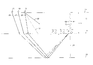
FIGURE 1 illustrates the geometry of the wavefield
trajectories useful in measuring the thickness of a
water layer;
CA 0220~426 1997-0~
FIGURE 2 is a suite of four time-scale traces
showing the pressure signature, velocity signature,
resolved up-going and resolved down-going seismic
transients as derived from one member of a common
receiver gather;
FIGURE 3 is a graph of the time delay progression
during an iterative cross-correlation process.
In Figure 1, a particle-velocity responsive
geophone V1 and a pressure responsive hydrophone P1 are
laid next to each other on the bottom 10 of a body of
water 12, the surface of which is designated as 14. For
purposes of this disclosure, units V1 and P1 are sensor
components that comprise a dual-mode sensor. To avoid
complicating the drawings, only three spaced-apart dual-
mode sensors are shown, but it is to be understood thatin practice many hundreds or even thousands of such
sensors may be laid out in practice by a cable servicing
ship.
An acoustic source, which may be towed at or near
the water surface by a shooting ship, generates a
wavefield in the water at successive spaced-apart
stations such as 16, 18, 20 that are offset from the
surface projections of the dual-mode sensor locations.
The offset is a selected multiple of the station spacing
which, in turn may be the same as the dual-sensor
spacing.
Each wavefield, as it is generated, propagates
along appropriate trajectories such as 22, 24, and 26,
through water layer 12 to insonify subsurface earth
strata such as 28, whence the wavefield is reflected
back towards the surface to be jointly detected by both
components of the dual-mode sensor such as V1 and P1 on
the water bottom 10. Trajectories 22, 24 and 26 are
shown converging at V1 to avoid complicating the
drawings but it should be understood that P1 is co-
located with V1 and receives the same energy over the
same travel path. Wavefield trajectories from three
CA 0220~426 1997-0~
source stations converging towards V1,P1, form a common
receiver gather having three members. Figure 2 is a
display of the pressure and velocity signatures for one
member of a common receiver gather formatted as a time
scale display. Five reflected seismic events are
distributed over a reflection-time gate of 1.5 seconds.
In addition to the reflected wavefields, seismic
energy arrives at the sensors by way of a direct path
such as 30, through the water 12 or refracted along the
water/bottom interface such as by path 32. For modest-
length offsets up to 600 meters or less, the direct and
refracted arrivals appear quite early on the time scale
recordings, well ahead of the shallow reflected
arrivals. In addition, by employing such a relatively
short offset gate the data trajectories approximate
normal-incidence ray paths as indicated by dashed line
34, Figure 1, thus avoiding the need for extensive
preprocessing. The angularity of the trajectories 22,
24, 26 in Figure 1 has been exaggerated for illustrative
purposes. In actual field work, the offset is short
compared to the depth to a reflector of interest, so
that the ray paths do indeed approach normal incidence.
Figure 2 is a display of four time-scale seismic
traces. Trace A represents the synthetically-generated
pressure signatures for the primary and first ghost
reflection of five reflected events. Trace B represents
the corresponding velocity signatures. The remaining
two traces will be discussed later.
Referring first to Figure 1, consider a geophone at
depth h in a water layer having a velocity c (about 1500
m/s in salt water). Let the normally-incident pulse 34
traveling upward past geophone V1 at time t=0, impinge
on the bottom of the geophone, to generate a positive-
going output signal such as 36, trace B, Figure 2. For
purposes of clarity, the second well-developed cycle of
the signal envelope is chosen as the argument.
Continuing upward at 38, Figure 1, the pulse encounters
CA 0220~426 1997-0~
the surface at time 0.5r = 2h/c. The air has a lower
impedance than the water. The reflection of the
velocity wave suffers no phase shift, that is, an
upward-moving particle remains upward moving after
reflection. After time r = 2h/c, the downward traveling
pulse 40, Figure 1, impinges on the top of the geophone
V1 which again registers positive as shown by 41, trace
B Figure 2. The impulse response G(~)v of the velocity-
signature ghost reflection is therefore
G(~)V = 1 - RsZ~ O<Rs<l,
Z = e~ i~r
Values for the surface reflectivity Rs lie in the range
of 0.7 - 0.9.
Consider now the hydrophone, Pl also at depth h in
the water. A normally-incident seismic pressure pulse
34 traveling upward registers as a positive hydrophone
output pulse at time t=O as shown at 43, trace A, Figure
2 and continuing upward along 38, Figure 1, as before.
For an ideal reflector, the pressure at the surface is
zero; up- and down-going pulses cancel at the surface.
Therefore, the reflected downgoing ghost pressure
reflection 44 is a rarefaction. At time r [r=2h/c] the
hydrophone registers a negative event 46, trace A,
Figure 2. The impulse response G(~)p for the hydrophone
pressure pulse is therefore
G(~)p = 1 + RsZ-
It is apparent that the velocity (V) and the
pressure (P) signatures can be resolved into up-going
(U) and down-going (D) energy components from:
U = P + V, (1)
D = P - V. (2)
The two-way travel time in the water layer can be
determined from reflection seismic data by finding the
time delay for which the up-going wave most closely
corresponds with the down-going wave as will be
explained next.
CA 0220~426 1997-0~
In the presently preferred method of operation, a
time gate within the wavefield is selected. A time gate
is selected having a span of about one second which
would include the first four events on traces A and B of
Figure 2, for example. The time window should be
selected from a shallow portion of the section where
relatively clean reflection data are available but not
so shallow as to receive interference from direct and
refracted arrivals. Common receiver gathers including a
desired number, such as 25-50, time scale traces
representative of velocity and pressure wavefields in
the time domain, are selected, preferably having offsets
of less than 600 meters.
The seismic signals represented by the pressure and
velocity signatures corresponding to each trace are
resolved into up-going and down-going wavefields from
formulations (1) and (2). Traces C and D represent the
primary up-going and reflected down-going or ghost
wavefields respectively. Because the traces shown in
Figure 2 were synthetically constructed for tutorial
purposes, the time delay, 48, that is, the difference in
arrival times, indicated by 52 and 54 between primary
and ghost due to the thickness of the water layer,
readily can be determined by inspection to be about 40
milliseconds which, at a water velocity of 1500 m/s,
would be 30 meters.
In real life, however, noise, instrumental
artifacts, the filtering effect of the earth itself, as
well as mutual reflection interference in the presence
of complex geology, all conspire to so complicate field
data as to require substantially more sophisticated
analyses than simple inspection as suggested by Figure
2. A preferred method of operation employs well-known
cross-correlation methods.
The wavefields resolved into up-going and down-
going wavetrains are transformed from the time domain to
the frequency domain such as by the well-known fast
CA 0220~426 1997-0~
Fourier transform algorithm. A time delay operator is
applied to the transform of the up-going wavefield. The
delayed up-going and the down-going transforms are
iteratively cross-correlated, discretely perturbing the
time delay operator after each iteration, such as by a
time shift corresponding to a preferred increment of
water depth, such as 10 centimeters, divided by the
water velocity. Cross-correlation can most easily be
done in the frequency domain because the correlation
process reduces to simple multiplication of the Fourier
spectra of the delayed up-going and the down-going
signal. The time lag that maximizes the zero-lag cross-
correlation function is a measure of the thickness of
the water layer as shown by the dotted function 50 shown
on the graph of Figure 3. Figure 3 shows the results of
iteratively cross-correlating traces C and D of Figure 2
with a zero-lag correlation peak at about 30 meters.
Preferably, because of the sheer volume of
calculations needed for a large survey area, the method
of this invention is computer implemented.
Preferably, the results of the cross-correlation of
each of the members of a common receiver gather are
averaged to provide an average water layer thickness.
In an alternate method, the transforms of the velocity
and pressure signatures of each member of a common
receiver gather are auto-correlated. The auto-
correlations are then stacked and the stacked auto-
correlations are then cross-correlated.
In areas of severe noise, it is contemplated that
the noise abatement filter, such as is taught by the
'492 reference, will be applied.
It is to be understood that the seismic data are
not gathered to provide a solution for a naked
formulation. The method and formulations disclosed here
are provided to more clearly depict sub-bottom earth-
layer topography by providing a continuous profile of
the water-layer thickness. Using that information,
CA 0220~426 1997-0~
static corrections can be generated to compensate for
the anomalous effect of an irregular low-velocity water
layer.
This invention has been described with a certain
degree of specificity by way of example but not by way
of limitation. Those skilled in the art will devise
obvious variations to the examples given herein. For
example, ghost reflection operators can be computed for
the velocity and pressure signatures to create a second
pair of pseudo-pressure and pseudo-velocity traces from
the up-going wavefield. Minimization of the measured
and pseudo pressure and velocity traces is a measure of
the correct two-way travel time in the ghost operator.
Another method would use the effects of the ghost
filters to equalize the reflection sequence for the
pressure and the velocity signals. Minimization of the
difference between the equalized traces indicates the
correct parameters in the ghost filter. By way of
example, but not by way of limitation, the acoustic
source is shown at or near the water surface. The
source may be deployed anywhere within the water layer
or it may be immersed in the mud at the bottom of the
water. All such alternate but equivalent methods will
fall within the scope of this invention which is limited
only by the appended claims.