Note: Descriptions are shown in the official language in which they were submitted.
CA 02205809 2001-02-08
27363-76,
1
METHOD AND DEVICE FOR RADIO COMMUNICATION IN TRAFFIC GUIDANCE
SYSTEMS
FIELD OF THE INVENTION
The present application is directed to a method and
device for radio communication between central and peripheral
units of a traffic guidance system. The central and peripheral
units communicate with one another via at least a first and
second voice channel and at least a first and second data
channel. The central unit includes a master terminal and the
peripheral units include at least one of vehicles and passenger
information systems. The central unit transmits messages to
the peripheral units via the first data channel, and the
peripheral units transmit responses to the central unit via the
second data channel. The central and peripheral units also
communicate via the first voice channel, and the peripheral
units communicate with each other via the second voice channel
when they are located at close range to each other.
BACKGROUND OF THE INVENTION
To ensure the smooth performance of medium and large
scale transportation companies, in particular, in public
commuter transportation, state-of-the-art computerized
operating guidance systems are used as described in "Moderne
Betriebsleitsysteme auf Basis von Datenfunknetzen" [State-of-
the-Art Operating Guidance Systems Based On Radio Data
Networks] Verkehr and Technik, Special edition, Issue 12, Erich
Schmidt Verlag, Berlin 1992 by Dr. J. Gehrig. Communication
between the system units: the master terminal, vehicles and
decentral control units, e.g., for influencing optical signal
units which control the flow of traffic, is normally performed
in real time via radio transmission. The point-to-point data
CA 02205809 2001-02-08
2736,3-76 .
2
transmission, for example, from a stationary point of the line
to the vehicles, often takes place via IR connection. The
radio network not only exchanges information between personnel
at the master terminal and drivers, it also transmits
information on optical and acoustical passenger at traffic
junctions or stations. Conversations between personnel at the
master terminal and/or the vehicles are usually transmitted
analog via at least one voice channel. For controlling
peripheral system units and for cyclic recording of actual
operating data, digital messages are used which are converted
into analog signals (modulation) and transmitted via at least
one data channel. To optimize the procedure within the
guidance system, decentral system-relevant information is
retrieved and analyzed. Therefore, it is of importance to the
master terminal to be in permanent contact with all system
units, in particular, with the vehicles. In state-of-the-art
traffic communication systems, preferably two data channels are
provided between the central master terminal and the peripheral
system units which enable permanent bi-directional radio
communication. A radio set provided in the vehicles may, for
example, receives and responds to the switching commands
transmitted in the first channel of the master terminal, which,
for example, contain a call request. After receiving a
spontaneous call or request, a response message is immediately
transmitted via the second channel from the vehicle to the
master terminal. From the master terminal current data can be
retrieved by the same method from the peripheral system units.
Further, if necessary, the radio sets contained in these
peripheral system units are instructed to switch to a specific
channel, in order to set up a radiotelephone connection. After
termination of the call, a signal is issued from the master
CA 02205809 2001-02-08
27363-76,
2a
terminal via the used voice channel, causing the radio set to
make the radio connection again via the two data channels.
Further, there is the possibility of switching the radio set to
another voice channel on which voice signals can be exchanged
between system units at close range over short distances.
The disadvantage with these known systems is that the
radio sets provided in the peripheral system units are largely
running to capacity as a result of monitoring the polling
messages (polling operation) transmitted in the first data
channel and, therefore, are not available for further use. If
the radio sets provided in the peripheral system units are used
alternatively for the transmission of voice signals in the
voice channels provided for said transmission, the polling
messages transmitted via the first data channel can no longer
be monitored.
SUMMARY OF THE INVENTION
It is the object of the present invention to provide
a method and a device for communication in traffic guidance
systems in that the data and voice channels reserved for
traffic operation can be better utilized. At the same time, it
must also be ensured that, in comparison to the known systems,
practically no data loss will occur.
According to one aspect the invention provides a
method for radio communication between central and peripheral
units of a traffic guidance system, the central and peripheral
units communicating with one another via at least a first and
second voice channel and at least a first and second data
channel, the central unit including a master terminal and the
peripheral units including at least one of vehicles and
passenger information systems, the method comprising: trans-
CA 02205809 2001-02-08
27363-76
2b
mitting messages from the central unit to the peripheral units
via the first data channel; transmitting responses from the
peripheral units to the central unit via the second data
channel; communicating between the central and peripheral units
via the first voice channel; communicating between the peri-
pheral units via the second voice channel when the peripheral
units are located at close range to each other, wherein the
peripheral units are composed of at least one receiver and a
transmitter, and the method further comprises: switching to the
second voice channel for normal operating conditions; allo-
cating time slots in the first data channel; polling, in the
allocated time slots, the peripheral units with the central
unit via the first data channel; switching the receiver to the
first data channel to receive the polling calls from the
central unit; switching the transmitter to the second data
channel to transmit response calls to the central unit, wherein
at least one of the peripheral units comprises an additional
second receiver permanently switched to the first data channel,
and the method further includes: receiving at the additional
second receiver the polling calls from the central unit; and
switching the transmitter to the second data channel to trans-
mit response calls to the central unit.
According to another aspect the invention provides a
method for radio communication between central and peripheral
units of a traffic guidance system which communicate with one
another via at least a first and second voice channel and at
least a first and second data channel, the central unit
including a master terminal and the peripheral units including
at least one of vehicles and passenger information systems, the
method comprising: transmitting messages from the central unit
to the peripheral units via the first data channel and from the
peripheral units to the central unit via the second data
CA 02205809 2001-02-08
27363-76.
2c
channel; communicating between the central and peripheral units
via the first voice channel; communicating between the peri-
pheral units via the second voice channel when the peripheral
units are located at close range to each other, wherein the
peripheral units are composed of at least one receiver and a
transmitter, and the method further comprises: switching to the
second voice channel for normal operating conditions;
allocating time slots in the first data channel; polling, in
the allocated time slots, the peripheral units with the central
unit via the first data channel; switching the receiver to the
first data channel to receive the polling calls from the
central unit; and switching the transmitter to the second data
channel to transmit response calls to the central unit.
According to another aspect the invention provides a
system for radio communication between central and peripheral
units of a traffic guidance system comprising: at least a first
and second voice channel; at least a first and second data
channel; the central unit being composed of a master terminal
having a master transmitter adapted to transmit polls and
switching commands to the peripheral units via the first data
channel; the central unit and the peripheral units being
coupled for voice communication on the first voice channel; the
peripheral units being coupled for voice communication in a
short range via the second voice channel; and the peripheral
units being composed of at least one of vehicles and passenger
information systems and the peripheral units comprising: a
transmitter adapted to transmit messages to the central unit
via the second data channel; a computer; and a receiver, the
receiver and the transmitter being switchable with exact timing
to the second data channel when a call from the central unit
via the first data channel is received, wherein, upon receiving
a call transmitted from the central unit via one of the second
CA 02205809 2001-02-08
2736,3-76.
2d
voice channel and the first data channel, the receiver and the
transmitter are switched to the first voice channel, whereby a
call between the personnel of the central unit and of the
peripheral units is enabled, and wherein the receiver and the
transmitter are automatically switched to a normal operating
condition in the second voice channel when no further informa-
tion from the central unit exists.
According to another aspect the invention provides a
system for radio communication between central and peripheral
units of a traffic guidance system comprising: at least a first
and second voice channel; at least a first and second data
channel; the central unit being composed of a master terminal
having a master transmitter adapted to transmit polls and
switching commands to the peripheral units via the first data
channel; the central unit and the peripheral units being
coupled for voice communication on the first voice channel; the
peripheral units being coupled for voice communication in a
short range via the second voice channel; and the peripheral
units being composed of at least one of vehicles and passenger
information systems and the peripheral units comprising: a
transmitter adapted to transmit messages to the central unit
via the second data channel; a computer; and first and second
receivers adapted to receive calls from the central unit, and
the second receiver being adapted to permanently receive calls
transmitted from the central unit via the first data channel;
the transmitter being switchable to the second data channel to
respond to calls from the central unit on the first data
channel; wherein, after receiving a call from the central unit,
the first receiver and the transmitter are switchable to the
first voice channel, whereby a call between the personnel of
the central unit and the peripheral units is enabled, wherein
the first receiver and the transmitter are automatically
CA 02205809 2001-02-08
27363-76.
2e
switched to a normal operating condition in the second voice
channel when no further information from the central unit
exists.
As a result of the inventive measures, the
utilization ratio of the data and voice channels available for
traffic guidance systems is optimized. At the same time, an
elevated utilization of the voice channels is achieved, without
losing the data transmitted by the master terminal via the data
channels.
BRIEF DESCRIPTION OF THE DRAWINGS
The invention will now be described in detail with
reference to the accompanying drawings, in which:
CA 02205809 1997-OS-21
P 15493.S01
-3-
Figure 1 shows the time sequence of radio signals which are transmitted
according to the first method via various data and voice channels;
Figure 2 shows the time sequence of radio signals which are transmitted
according to a second method via various data and voice channels;
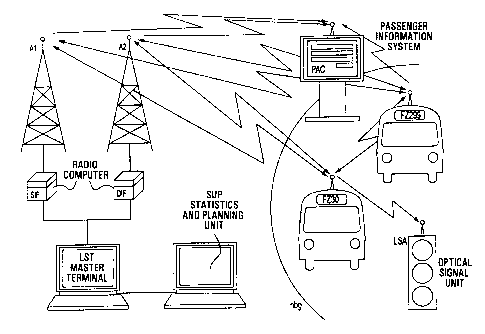
Figure 3 shows an overview of the central and peripheral system units which
communicate with each other according to the first or second method
via data and voice channels;
Figure 4 shows a peripheral system unit for communication according to the
device provided in the first method; and
1 o Figure 5 shows a peripheral system unit for communication according to the
device provided for the second method.
Figure 1 shows the data sequences in a first and in a second data channel DKl,
DK2, as well as the sequence of voice signals in a first and in a second voice
channel
SK1, SK2. In the first data channel DK1, data are transmitted from a central
system
unit, e.g., the master terminal LST shown in Figure 3 to peripheral system
units, e.g.,
to the vehicles FZ or passenger information systems PAC signalized to the
system.
As result of the data transmitted in a first data channel DK1, the vehicles FZ
(or the
other peripheral system units PAC) transmitted corresponding response data via
the
second data channel DK2 to the master terminal LST. The master terminal LST
can
2 o also transmit the request to the vehicle FZ to switch to the first voice
channel SK1,
enabling a call between the master terminal personnel and the driver, without
blocking the two data channels DKl and DK2. After completion of the call, the
master terminal LST transmits to the vehicle FZ via the first data or voice
channel
DK1 or SK1 the request for switching the channel. To enable the transmission
of
2 5 essential data during a call to the vehicle FZ or from the vehicle FZ to
the master
terminal LST, the subsequently described measures are initiated according to
the
invention. Of major importance for the smooth operation of data communication,
is
the second voice channel SK2 via which communication takes place mainly in the
short range, e.g., between the drivers. According to the invention, this so-
called
3 o short-range channel SK2 also is used to transmit information spontaneously
and
CA 02205809 1997-OS-21
P15493.501
-4-
without delay from the master terminal LST to the vehicle FZ. As such great
importance is attached to the short-range channel SK2, according to the
invention,
said channel is used as a standard or default channel, without losing messages
for the
vehicle FZ, which are transmitted in other channels. Following communication
on
other voice or data channel, the operation, therefore, is switched back to the
short-
range channel SK2. An exception merely is the change in channel which can
occur
during a call from the first voice channel SK1. In this case, the return to
the short-
range channel SK2 takes place only after completion of the call. The
peripheral
system units LSA, PAC, which are not provided for communication on the voice
1 o channels SK 1, SK2, remain in normal operating condition during which no
further
information from the central unit LST exist, while said units are switched to
receiving
data transmitted on the first or other data channels DKI, DK3.
Basically, these conditions can be satisfied by the two inventive solutions
described in the following:
In a first inventive embodiment, data transmission takes place in the time
slot
process on the first two data channels DK1, DK2. Each peripheral system unit
FZ,
PAC is allocated a time slot within which the relevant data are transmitted to
the
corresponding unit. In Figure 1, for example, are provided time slots for 300
peripheral system units FZ, PAC which are polled in blocks of ten unit. Each
polling
2 o block contains preferably twelve time slots of which the first is provided
for
transmitting event-specific information to one, several or all peripheral
system units
FZ, PAC. For example, the time slot allocation to all reported peripheral
systems FZ,
PAC takes place via the first time slot when starting the system or after a
system
interruption. Further, the group polling, which can be parameterized by the
master
2 5 terminal LST, can be transmitted via said first time slot. The second time
slot, which
enables the flexibilization of data communication is allocatable for random
polling
operations. The remaining ten time slots are provided for the selective
polling of the
peripheral system units FZ, PAC concerned. The thirtieth polling block, within
which the communication to the peripheral system units FZ, PAC is generated
with
3 o address numbers 291 through 300, closes the polling cycle. After logon,
each of the
CA 02205809 1997-OS-21
P15493.501
-5-
300 peripheral system units FZ, PAC are familiar with the time at which the
master
terminal LST will contact with said unit and, therefore, will have at its
disposal the
remaining cycle time (more than 99%) for transmitting voice signals to voice
channels SK1, SK2. A radio set FG1 (see Figure 4) provided in the peripheral
system
units FZ, PAC, which, among other things has a receiver and a transmitter RX
or TX,
normally operated in the short-range channel SK2 and for the duration of the
time slot
periodically changes to the data channels DK1 and DK2. As a polling cycle
with, for
instance, 300 radio partners may take a relatively long time (30* 12 time
slots * 0.05
seconds per time slot, this results in an 18 second period per time slot), a
data
1 o exchange may be necessary between a peripheral system unit FZ, PAC and the
master
terminal LST. In response to the group polling (broadcast messages on the
first data
channel DK1, time slot S/M), which is transmitted to the first time slot
within the
polling block, the peripheral system unit FZ, PAC can transmit to the second
data
channel DK2 a message to the master terminal LST. This message can, for
instance,
be a request for communication between the master terminal LST and the
peripheral
system unit FZ, PAC via the first voice channel SK 1. If, however, the master
terminal LST desires to communicate with the peripheral system unit FZ, PAC
via
the first voice channel SK1, without waiting for the remaining cycle time,
said unit
transmits a message tg-c via the short-range channel SK2 to the peripheral
system
2 o unit FZ, PAC concerned and causes said unit to switch directly to the
first voice
channel SK1 or temporarily to the first data channel DK1 for receiving. Not
only
during communication in the short-range channel SK2, but also during
communication in the voice channel SK2, data may, if necessary, be transmitted
sporadically via other data channels (e.g., data channel DK3) to other
peripheral
2 5 system units PAC, LSA. Requests for permission to pass addressed to
optical signal
units LSA (Figure 3) are transmitted via the data channel DK3. Further,
spontaneous
departure messages from a vehicle FZ can be transmitted to the system units
PAC via
the data channel DK3.
Figure 1 shows a possible communication sequence within the various data
3 o and voice channels, DK1, DK2, DK3, SK1 and SK2 for a vehicle with address
P15493.501 CA 02205809 1999-04-27
-6-
number 30 (FZ30), which is equipped with a radio set FG1 according to Figure
4.
Prior to time tl, the radio set FG1 of the vehicle FZ30 is switched to the
voice
channel SK2 for communication with other peripheral system units FZ which are
located in the vicinity of the vehicle FZ30. For example, a driver who is
overdue
must notify the driver of a vehicle FZ, which is to make the connection, of
the delay.
Further, the driver is able to permanently obtain information on the traffic
procedure
in his immediate vicinity by listening in the short-range channel SK2. At the
time tl,
there exists the request for transmitting a message to the master terminal
LST. Since
the message is important, the driver should not wait for the remaining cycle
time of
1 o maximum 18 seconds until the message has been transmitted to the master
terminal
LST. The receiver RX of the radio set FG 1 is, therefore, switched at the time
t 1 to
the first data channel DKl. Following detection of group polling from the
master
terminal LST (time t2), which takes place within the first time slot of the
next polling
block, the radio set FG 1 transmits via the second data channel DK2 the urgent
message (alarm, robbery, accident, etc.) in the associated time slot to the
master
terminal LST and subsequently (time point t4) switches back to the short-range
channel SK2. Further, the acknowledgment of the message can be awaited on the
first data channel DK1. The call interruption u21, as caused by the above-
described
process, corresponds in terms of length to approximately S time slots. At a
2 o subsequent time t5, a request message must be transmitted spontaneously
via the data
channel DK3, e.g., to an optical signal unit LSA. Upon broadcasting the
message,
at the time t6, the radio set FG 1 is switched back to the short-range channel
SK2.
The call interruption u22 caused by this process corresponds in terms of
length to
approximately three time slots. At this time t7, the master terminal LST will
contact
the vehicle FZ30 and transmits for this purpose via the short-range channel
SK2 a
switch-over message tg-c which is addressed to the vehicle FZ30. In the
described
case, the radio set FG1 is initially to be switched over to the first data
channel DK1
and later, following receipt of further instructions (time t8), to the first
voice channel
SK1. Following the acknowledgment of the message (time ts)transmitted by the
3o master terminal LST, the radio set FG1 at the time t10 is switched over to
the first
CA 02205809 1999-04-27
-
voice channel SK1 on which the driver now is able to
communicate with the master terminal personnel. Preferably,
the voice channel SK1 is reserved prior to the call request by
the master terminal LST (see reservation block kr). Between
the times tll and t12, a further request message is
transmitted via the third data channel DK3 to an optical
signal unit LSA as a result of which during approximately
three time slots, an interruption ull of the call occurs
between the master terminal LST and the vehicle FZ30. At the
time t13, the radio set FG1 switches to the first data channel
DK1 to receive the vehicle-specific polling transmitted by the
master terminal LST and acknowledges said polling at the time
t14 and switches back to the voice channel SK1 at the time
t15. The interruption u12 caused by this process corresponds
approximately to the length of 5 time slots. At the time t16
the master terminal LST signals the end of the call and also
transmits a change-back signal rst of several milliseconds of
a specific frequency after which the radio set FG1 is switched
back to the short-range channel SK2. The interruption u23 of
communication in the short-range channel SK2, Which began at
the time t7, is dependent upon the duration of the call
between the master terminal LST and the vehicle FZ30.
With low expenditure - only one radio set (see Figure 4)
is needed per peripheral system unit FZ, PAC - the inventive
method can guarantee optimal use of the provided data channels
SK, DK. The driver of the vehicle FZ30 is always well
informed, as he receives messages via the short-range channel
SK2, and he may be contacted periodically or spontaneously by
the master terminal LST.
CA 02205809 1999-04-27
_ 7a
The inventive method thus allows data communication
between the master terminal LST and the vehicle FZ during
Which the driver conducts a call via the first or the second
voice channel SK1, SK2. The operating processes, for which
sporadic or routine data transmission is required, thus are
not influenced by channel switching from and to voice channels
SK1 or SK2. For example, during the call, information text
can be retrieved for passengers or operating data from the
onboard computer (see Figure 3 onboard computer IB) of the
vehicle FZ.
By reducing the equipment expenditure in the peripheral
system units FZ and PAC to a minimum, the described method and
device, however, are unable to
CA 02205809 1997-OS-21
P 15493. SO 1
_g_
guarantee the elevated demands of desired flexibility at any time. As a result
of the
cyclic monitoring of the polling transmitted by the master terminal LST in the
data
channel DK1, once per polling cycle or once transmitted call block (time slot
2), time
losses or undesired interruptions of communication occur in the voice channels
SK1,
SK2. Further, the message tg-c is transmitted via the short-range channel SK2
to the
vehicle FZ only if the signal transmitted by the master terminal LST is
adequately
powerful in relation to other signals occurring in the short-range channel
SK2. For
this reason, the spontaneous data transmission from the master terminal LST to
the
peripheral system units FZ cannot be guaranteed at all times with this method
and the
1 o corresponding device.
To reduce the described loss of time, the method described in the following
by means of Figure 2 is preferably applied, in that a radio set FG2 is
required with
two receivers RX1, RX2 and one transmitter TX1 (see Figure 5). The first
receiver
RXl is provided for receiving signals transmitted on the voice channels SK1,
SK2.
Via the second receiver RX2 are received simultaneous the same signals
transmitted
in the first data channel DK1. As a result, all interrogations transmitted by
the master
terminal LST are monitored by the peripheral system units FZ, PAC. The
sequence
of the peripheral system units FZ, PAC to be interrogated can be selected
randomly
and thus can be optimized in terms of operation. There is no rigid, cyclic
2 o transmission of the vehicle specific interrogations in allocated time
slots. At
preferably regular intervals, however, collective calls (S/M) are transmitted
which are
loaded by all peripheral system units FZ, PAC for transmitting important
messages.
Further, the master terminal LST may transmit via the first data channel DK1
information texts of preferably variable length which are transmitted to the
peripheral
system units FZ, PAC to be contacted. Figure 2 shows that first the vehicles
FZ are
contacted with address number 57 and 32, subsequently a general poll is
transmitted
to all vehicles FZ, and then the vehicles FZ or other peripheral system units
PAC with
address numbers 3, 30, 9, etc., are called. The short-range channel SK2 is
again used
as standard or default channel in the peripheral system units FZ. The
transmitter TXl
3 o transmits data in the data channels DK2, DK3 or voice signals in the voice
channels
CA 02205809 1997-OS-21
P 15493 . SO 1
-9-
SK1, SK2, in necessary.
Figure 2 shows a possible pattern of communications within the various data
and voice channels DKI, DK2, DK3, SK1 and SKZ according to this second method,
together with the extended radio set FG2 according to Figure 5 for the vehicle
with
address number 30 (FZ30).
Prior to the time tl, the first receiver RX1 of the radio set FG2, which is
provided in the vehicle FZ30, is switched for communication with short-range
operating vehicles FZ to the short-range channel SK2. Between the times tl and
t2,
a message is transmitted spontaneously via the transmitter TX1 on the third
data
1 o channel DK3, e.g., to an optical signal unit LSA. The resulting call
interruption u21'
normally corresponds to the length of approximately three time slots. At the
time t4,
the vehicle FZ30 receives information which are to be transmitted to the
master
terminal LST. After receiving the general poll (S/M) detected by the second
receiver
RX2, the transmitter TX1 is switched to the data channel DK2 and transmits the
message to be transmitted between the times t4 and t5. The transmission in the
short-
range channel is continued between the times t5 and t6, as well as later
between t7
and t9. Between the times t6 and t7, the subsequent poll is answered by the
master
terminal LST. At a later time t8, the second receiver RX2 receives a call from
the
master terminal LST requesting it to switch to the first voice channel SK1.
This
2 o request is acknowledged at a later time t9 by a response message via the
second data
channel DK2, whereupon, at the time t10 switching is done for transmission on
the
first voice channel SK1. The communication on the voice channel SKl between
the
master terminal LST and the vehicle FZ30 is interrupted between the times tl 1
and
t12 in favor oftransmitting a request message via the third data channel DK3.
At a
2 5 later time t 13, the second receiver RX2 receives a further call from the
master
terminal LST, which is acknowledged by the response message between the times
tl4
and t15. At the time t16, a further call is made in which the vehicle FZ30 is
informed
of the termination of the call. An acknowledgment of this call takes place
between
the times tl7 and t18, after which the first receiver RXl is switched back to
the short
3 o range channel SK2.
CA 02205809 1997-OS-21
P15493.501
-10-
Figure 3 shows central and peripheral system units, LST, SUP or PAC, FZ30,
FZ299, LSA of a communication system, which after the first or second method,
if
necessary, communicate with one another via the data and voice channels DK1,
DK2,
DK3, SK1, and SK2 according to the above described method. For transferring
data,
the system units LST, SUP or PAC, FZ041,..., FZn preferably use the devices
and
modulation processes known from EP A 0 566 773. However, other devices are
known to the expert, by means of which data and voice signals can be
transmitted via
the existing channels. The master terminal LST communicates with the
peripheral
system units FZ, PAC via the data channels DK1 and DK2 and, if necessary, via
the
1 o voice channels SK1, SK2. The transmitter and receiver units of the radio
computer
SIF or DIF in the master terminal LST, which are connected with antennas A1 or
A2,
normally have a transmitting power corresponding to the transmitting power of
the
transmitters TX, TX1 which are provided in the peripheral system units FZ,
PAC.
The master terminal LST normally transmits with a common wave frequency and
performs a diversity analysis of the received signals. These methods are
already
being used with several operational installations. The voice signals to be
exchanged
between the master terminal LST and vehicle FZ are transmitted via the antenna
A1
in the voice channel SK1. For spontaneous contacting the vehicle FZ30
according
to the first method, the master terminal LST transmits a message (tg-c) via
the
2 o antenna A1 and the short-range channel SK2 to the vehicle FZ to be
contacted. As
the short-range channel SK2 normally is occupied by calls, the signal
intensity of the
call (tg-c) must clearly exceed the signal intensity of local calls. The
transmitting
power of the vehicle FZ and the walkie-talkie, which is necessarily used in
the short-
range channel SK2, is smaller by the factor 10... 100 than the transmitting
power of
2 5 the master terminal LST in the second voice channel SK2. The vehicles FZ30
and
FZ299 located within the short-range area, as shown in Figure 3 (see Figure 3,
short-
range boundary nbg, for example, of the vehicle FZ299), can communicate with
each
other via the short-range channel SK2. Between intervals, the vehicle FZ30
transmits
request messages via the data channel DK3 to the optical signal unit LSA, in
order
3 o to cause switch-over to green light. Likewise, departure messages, for
example, from
CA 02205809 1997-OS-21
P 15493 . SO 1
-11-
the vehicle FZ299 for the direct control of passenger information systems PAC
(e.g.,
transmission of a command for canceling a line display after departure of the
vehicle
FZ299), can be transmitted spontaneously on another data (e.g., DK3). The
master
terminal LST transmits polling messages via the radio computer DIF and the
antenna
A 1 on data channel DK2 to all logged on peripheral system units FZ, PAC which
return responses in the provided for time slots replays via the second data
channel
DK2. The data received for analysis by the peripheral system units FZ are
transmitted to the central system unit SUP (statistics and planning), as a
result of
which the existing planning data are revised and optimized.
1 o Figure 4 shows the radio set FG 1 provided for a peripheral system unit
FZ,
PAC for communication according to the first method, which is provided with a
receiver and a transmitter RX and TX respectively which are connected via data
and
control lines with the onboard computer IB and can be connected via an antenna
multiplexer or a change-over switch US with an antenna FA. By means of the
onboard computer IB, which is provided with a modulation and demodulation
unit,
which, among other things, serves to control the modules provided in the
vehicle FZ,
the channel switch-over described in Figure 1 is performed and data are output
or
entered as a result of the instructions received by the master terminal LST or
the
driver.
2 o The radio set FG shown in Figure 5 is provided with another receiver RX2
connected with an Antenna FA2 by means of which messages are monitored which
are transmitted by the master terminal LST via the first data channel DK1,
even if the
receiver RX1 and transmitter TX1, which are interconnected via the change-over
switch US with the antenna FA1, are switched to the operation in one of the
voice
channels SK1, SK2. With this second method, calls of the master terminal LST
via
the short-range channel SK2 are thus no longer necessary. Further, the onboard
calculator configuration shown in Figure 5 corresponds to that shown in Figure
4.
The devices shown in Figure 4 and Figure 5 are preferably custom configured
modular units. With large transportation systems, additional data and voice
channels
3 o DK, SK may exist under certain conditions, between which the transmitters
and
CA 02205809 1997-OS-21
P15493.501
-12-
receivers (RX, TX, or RX1, RX2 and TX1) are switched according to the above
methods. For example, for communication between personnel of the master
terminal
LST and the vehicle FZ, switching may be possible to a third voice channel if,
for
example, the first voice channel SKl is busy. Further, a fourth data channel
can be
provided if switch-over to the first receiver RX1 occurs periodically or if
said channel
is permanently monitored by a third receiver. Likewise, different vehicles FZ,
e.g.,
rail vehicles, buses or taxis, can be allocated independent data and voice
channels
DK, SK.
The radio set FGl or FG2 shown in Figure 4 and Figure 5, which is provided
1 o for the peripheral system unit vehicle FZ, has the minimal configuration
of all
elements which are required for radio communication according to the inventive
method.