Note: Descriptions are shown in the official language in which they were submitted.
CA 02205870 1997-05-22
WO96~16782 PCT~S/04492
o ~ .~1 ~i ~ f~. f . ~ ,sr foa.~ U~; ~ 'A ~
~i~Yi~e ~ v~A ~or ~
The present invention relates to a process and a device for
producing foam~ using carbon dioxide dissolved under
pressure as blowing agent, wherein the material to be
expanded is mixed under pressure with preferably liquid
carbon dioxide and is then expanded with the formation of
foam. Liquid starting materials for plastics are preferebly
used as materials which can be expanded and which can be
hardened by means of a polyaddition or polycondensation
reaction, which is initiated after expansion, to give
foamed plastics. The invention relates in particular to
polyurethane foams.
When producing polyurethane foams, at least one of the
reactive components (polyisocyanate and compounds which
contain isocyanate-reactive hydrogen atoms, in particular
polyols) is mixed with a liquid or gaseous blowing agent,
then mixed with the other component and the mixture
obtained is fed either batchwise into a mould or
continuously onto a conveyer belt, where the mixture
expands and hardens.
There are a number of processes with widespread application
in industry for producing foam materials. On the one hand,
liquids which evaporate at low temperature, such as low
molecular weight chlorinated hydrocarbons, methylene
chloride, pentane etc. are used, which evaporate out of the
still liquid reaction mixture and form small bubbles
(physical foam production). Furthermore, air can be beaten
CA 0220~870 1997-0~-22
WO 96/16782 PCI'IEP95/04492
into the reactive mixture or into one of the components
(mechanical foam production) and finally water may be added
to the polyol component as a blowing agent during
polyurethane foam production, which releases carbon dioxide
as the foam-producing gas after being mixed with the
isocyanate component due to reaction with the isocyanate
(chemical foam production).
For reasons of environmental compatibility and occupational
hygiene and because of the comparatively high solubility of
liquid carbon dioxide in the polyol component, liquid
carbon dioxide has already been proposed as a blowing agent
on several occasions (GB-A 803 771, US-A 3 184 419).
However, carbon dioxide has not hitherto been used in
industry, evidently due to the difficulties involved in
producing uniform foams when the pressure in the reactive
mixture is, as required, reduced from pressures of between
10 and 20 bar. The problem is that on the one hand the
carbon dioxide evaporates relatively suddenly immediately
after reducing the pressure, so there is a very large
increase in the volume of the reaction mixture, by a factor
of for example about 10, which is difficult to control and
on the other hand there tends to be time-lags - which may
be 3 to 6 bar below the equilibrium vapour pressure of CO2
at the particular temperature - in the release of carbon
dioxide from the reactive mixture, so that sudden,
explosive releases of carbon dioxide occur with the result
that large blisters or voids are included in the expanded
material.
According to DE-A 2 628 785, the introduction of air into
the polyol component, before carbon dioxide is dissolved
therein, has already been suggested, evidently to provide
nuclei for the release of carbon dioxide.
CA 0220~870 1997-0~-22
WO 96/16782 PCI'IEP95/044g2
According to EP-A 145 250, the ability of carbon dioxide to
form adducts with water and other low molecular weight
liquids is utilised, in order to produce the delayed
release of carbon dioxide from the reactive mixture so that
foam formation due to the release of carbon dioxide begins
only after the pressure has been reduced in the reactive
mixture. After destruction of the adduct, the water is then
available as an additional chemical blowing agent. However,
the controllability of foam formation in a large scale
process is not really improved by this procedure because
both the formation of the adduct and its decomposition are
extremely labile in the presence of the other conditions
prevailing in the reactive mixture, except when using
adducts prepared in a separate step, which are also
described in the said reference, with the aid of low
molecular weight tertiary amines which apparently have a
considerably extended decomposition time as compared with
spontaneously formed water/CO2 adducts.
Combinations of physically dissolved carbon dioxide and
other physical or chemical blowing agents which boil at low
temperature, such as water or chlorinated hydrocarbons, are
also proposed, in accordance with EP-A 89796.
None of these proposals has led to industrially applicable
solutions for the use of CO2, physically dissolved under
pressure, as a blowing agent for the production of
polyurethane foams.
The tests underlying the present invention were based on
the concept that the conditions under which the
polyurethane reactive mixture containing CO2 under pressure
is expanded have an essential effect on the formation of
the foam.
CA 0220~870 1997-0~-22
WO 96/16782 PCI~/EP95/04492
According to US-A 3 184 419, the pressurised reactive
mixture containing carbon dioxide which emerges from the
m; ~; ng device is evidently suddenly expanded through a
valve. According to EP-A 145 250, expansion should take
place gradually, it being possible for the gradual
reduction in pressure to take place while the reactive
mixture containing carbon dioxide flows through a pipe. In
this case release of some of the gas while still inside the
pipe is not necessarily regarded as a disadvantage because
this process may assist the formation of bubble nuclei.
Within the context of the tests underlying the present
invention, it has however been shown that such a premature,
i.e. spontaneous and non-induced, formation of bubble
nuclei is rather disadvantageous for the pore structure of
the foam because such a spontaneous formation of bubble
nuclei generally results in a foam which not only has a
very variable pore structure, but which also has large
holes and voids.
On the basis of these and other observations, the following
requirements were placed on the development of a process
for preparing foam materials made from two-component
reactive plastics using carbon dioxide which is physically
dissolved under pressure as a blowing agent:
1. The formation of bubble nuclei in the liquid two-
component reactive mixture must be controlled in such
a way that every bubble nucleus produced can
participate in an identical manner in the release of
carbon dioxide from the reactive mixture, so that as
uniform pores as possible are produced.
2. When inducing bubble nuclei, the number of bubble
nuclei produced should already correspond to the
CA 0220~870 1997-0~-22
WO 96tl6782 r~ 5S/04492
number of pores in the hardened expanded plastic
material.
3. The controlled, induced production of bubble nuclei
must take place at that moment in time at which the
liquid reactive mixture changes from a state which is
not saturated with dissolved carbon dioxide to a state
in which it is supersaturated with carbon dioxide,
i.e. at that moment in time at which it expands from a
pressure above the saturation pressure of the
dissolved carbon dioxide to a pressure which is below
the saturation pressure of the dissolved carbon
dioxide.
4. Immediately after the formation of nuclei, the
greatest possible degree of supersaturation of
dissolved carbon dioxide should be produced in the
reactive mixture. i.e. expansion from a pressure above
the equilibrium pressure o~ the dissolved carbon
dioxide to ambient pressure should take place as fully
instantaneously as possible.
It was found that the requirements mentioned above can be
satisfied when the reactive mixture which contains carbon
dioxide dissolved under pressure is expanded with the
production of high rates of shear in the reactive mixture.
Accordingly, the present invention provides a process for
producing foam materials from two-component reactive
plastics using carbon dioxide as a blowing agent by mixing
at least one of the reactive components with carbon dioxide
under pressure, mixing the reaction components while
maintaining a pressure which is greater than that of the
saturation pressure of the carbon dioxide in the mixture,
CA 0220~870 1997-0~-22
WO 96/16782 r~,l /hr5510~92
expanding the reactive mixture containing carbon dioxide
and hardening, characterised in that expansion is performed
suddenly with the production of high rates of shear.
The rates of shear produced during expansion should be at
least 104/second, in particular at least 105/second. Rates
of shear of greater than 106/second are particularly
preferred.
A means which is suitable for expansion and for producing
high shear rates is at least one passageway for the
reactive mixture with a size in at least one dimension of
less than 1 mm, preferably 0.05 to 0.5 mm, more preferably
0.1 to 0.3 mm and most preferably 0.08 to 0.15 mm.
The at least one passageway may be designed in the form of
a fine-mesh sieve, a perforated plate, a slotted grid or an
extended slit. The extension of the passageway in the
direction of flow should be m; nim~l . Preferably the
extension in the direction of flow should be no larger than
1 mm, and most preferably no larger than 0 5 mm.
Perforated plates with a thickness of 0.1 to 0.5 mm are
particularly suitable. In the case of longitu~i n~l 1 y
extended slits it is usually necessary, due to fabrication
requirements, for their dimensions in the direction of flow
to be 0.5 to 1 mm.
The difference in the pressure of the reactive mixture
upstream and downstream of the passageway is usually
between 5 and 20 bars, preferably 7 to 15 bars, and most
preferably 8 to 12 bars.
The shear rate is the gradient of the rate of flow
transversely to the direction of flow.
CA 02205870 1997-05-22
WO96/16782 P~ 5S/04492
The rate of shear for a slit can be approximately
calculated from the free (open) cross-sectional area Q of
the opening and the volume flow V passing through the
opening by assuming a linear flow profile. The rate of
shear for a slit of slit width D is therefore:
S = 2 V/Q:l/2D (approximation for a flow profile in the
form of a triangle with sides of identical
lengths).
The rate of shear for a perforated plate with n openings of
a radius R and a cross-sectional area q is:
S - 3 V/n q:R (approximation for a flow profile in the
form of a circular pyramid).
The two-component reactive plastics material is preferably
a polyurethane plastics material produced by the
polyisocyanate-polyaddition process.
Although the high rate of shear which is produced as the
reactive mixture passes through the at least one opening
with a low cross-sectional size is generally sufficient to
obtain a sufficiently large number of bubble nuclei, it can
be advantageous to produce additional bubble nuclei in the
customary manner by introducing air or nitrogen into at
least one of the reaction components of the reaction
mixture before they are mixed, in particular, for example,
when insufficient supersaturation with dissolved CO2 is
produced as the mixture passes through the at least one
opening of small cross-sectional size as a result of a low
content of CO2 in the reactive mixture.
In order to obtain an as high as possible supersaturation
CA 0220~870 1997-0~-22
WO96tl6782 PCT~ 5/04492
of the reactive mixture as it passes through the at least
one opening with a small cross-sectional size, the pressure
of the reaction mixture prior to its entry through the
opening should therefore only be slightly higher than the
~aturation vapour pressure of the dissolved carbon dioxide.
If therefore, according to a preferred variant o~ the
invention, carbon dioxide is only dissolved in the polyol
component for producing the reaction mixture containing
carbon dioxide, the pressure of the reaction mixture is
reduced, by means of a pressure-reducing valve, after it
issues from the m; ~; ng apparatus in which the polyol and
isocyanate components are mixed, to a pressure slightly
higher than the saturation vapour pressure of the mixture,
which can for example be between 60 and 80 % of the
saturation vapour pressure of the polyol component
containing carbon dioxide (upstream of the mixing
apparatus).
Aliphatic, cycloaliphatic, araliphatic, aromatic or
heterocyclic polyisocyanates, such as are described, for
instance, by W. Siefken in Justus Liebigs Annalen der
Chemie, 562, pages 75 to 136 are used as component A.
Aromatic polyisocyanates are preferably used, particularly
preferably polyisocyanates which are generally readily
obtainable industrially, e.g. 2,4- and 2,6-toluylene
diisocyanate and any mixtures of these isomers (UTDI''),
polyphenyl-polymethylene polyisocyanates, of the kind
prepared by aniline/formaldehyde condensation and
subsequent phosgenation ("crude MDI") and polyisocyanates
containing carbodiimide groups, urethane groups,
allophanate groups, isocyanurate groups, urea groups or
biuret groups ("modified polyisocyanates"), in particular
those modified polyisocyanates which are derived from 2,4-
--~= =
CA 0220~870 1997-0~-22
WO 96116782 P~ 55/o4492
and/or 2,6-toluylene diisocyanate.
The second component B (Upolyol component") consists of
compounds containing at least two hydrogen atoms which are
capable of reacting with isocyanates and have molecular
weights generally between 60 and 5000, preferably between
100 and 2000, in particular between 200 and 800. These are
understood to include, in addition to compounds containing
amino groups, thiol groups or carboxyl groups, preferably
compounds containing hydroxyl groups, in particular
compounds containing 2 to 8 hydroxyl groups, especially
those having molecular weights between 200 and 2000,
preferably 300 to 1200, e.g. polyesters, polyethers,
polythioethers, polyacetals, polycarbonates and
polyesteramides ha~ing at least 2, generally 2 to 8, but
preferably 2 to 6, hydroxyl groups, of the kind known per
se for producing polyurethane foams; polyether polyols are
quite specifically preferred.
Compounds which are suitable for use as the polyol
component are described on pages 6 to 9 of EP-B 121 850.
Furthermore, water, other blowing agents, foam stabilisers,
catalysts and other auxiliary agents and additives known
per se may optionally be used to prepare the reactive
mixture. These additional agents known per se which can be
used are disclosed on pages 9 to 11 of EP-B 121 850.
According to the invention, water is particularly
preferably used as an additional blowing agent in an amount
of most preferably 1 to 7 wt.~, based on the reactive
mixture. Water is particularly preferably used in an amount
of 2 to 5 wt.%.
CA 0220~870 1997-0~-22
WO 96tl6782 PCT/EP95/04492
The additional agents which can be used can be supplied
separately to the m; xi ng apparatus for m; X~ ng the
isocyanate component and the polyol component or else are
mixed with one of the two main components before m; X; ng the
isocyanate with the polyol, wherein additional water and
any other additional components which react with isocyanate
should only be admixed with the polyol component.
The process technology for preparing polyurethane foams is
described in principle in Becker/Braun, Kunststoff-
Handbuch, vol. 7: Polyurethane, 1993, pages 143 to 149, in
particular in Fig. 4.8 and Fig. 4.9 on page 148.
The components are preferably mixed in a so-called low
pressure stirred m; X; ng chamber, wherein according to the
invention the pressure prevailing in the mixing chamber is
greater than the saturation pressure of the dissolved
carbon dioxide.
Carbon dioxide is dissolved in one or more of the
components, in particular the polyol component, before
introducing the components into the mixing head. Carbon
dioxide is preferably dissolved in an amount of 1 to
7 wt.%, preferably 2 to 5 wt.%, based on the total reactive
mixture. Dissolution of carbon dioxide, preferably only in
the polyol component, may take place in any manner, e.g.
a) gaseous carbon dioxide is mixed into the polyol using
a stirrer in a container holding the polyol component
which is maintained at a pressure of 15 to 25 bar;
b) liquid carbon dioxide is mixed with the polyol at room
temperature, e.g. in a static mixer at a pressure of
70 to 80 bar, and then expanded to a pressure of 15 to
CA 0220~870 1997-0~-22
WO 96/16782 ~ 5/04492
25 bar before introduction to the low pressure stirred
m; ~; ng head;
c) liquid carbon dioxide, cooled to e.g. -20~C, is mixed
with the polyol component which is at room temperature
at a pressure of 15 to 25 bar, wherein m; ~; ng is
performed in such a way that the carbon dioxide is
dissolved in the polyol component before it can
evaporate.
It was found that the preferred alternative c) is
particularly successful, due to the high tendency of the
carbon dioxide to gO into solution, using a high-speed flow
stirrer which is located in the polyol pipeline at the
inlet point for the liquid carbon dioxide.
The components in the reactive plastics material, at least
one of which contains the dissolved carbon dioxide, are now
fed to the m; xi ng head, mixed therein and expanded on
issuing from the m; ~; ng head with the production of the
high rates of shear according to the invention. For this
purpose, the at least one passageway with a small cross-
sectional size in at least one dimension, is located at the
outlet of the m; X; ng head. The exit opening is preferably a
slit or a sieve plate with a small cross-sectional size.
The reactive mixture containing carbon dioxide passing
through the slit expands immediately after passing through
the slit within a very short time which may be in the range
1/10 to 1/1000 seconds. In this case essentially all the
dissolved carbon dioxide present is released, thereby
producing a foam with a relatively uniform foam structure.
-
Provided the composition of the reactive mixture favoursthe spontaneous production of CO2 adducts, e.g. with
CA 0220~870 1997-0~-22
WO 96/16782 PCT/EP95/044~2
compounds which contain hydroxyl groups, additional CO2 is
released at a time delayed by the requisite decomposition
time o~ the adducts, which leads essentially to enlargement
of the foam bubbles already present. When using water as an
additional chemical blowing agent, the foam Urises'' further
at the start of the isocyanate reaction with water.
The reactive mixture, which is suddenly expanded with a
pressure drop of 5 to 15 bar and the production of high
rates of shear, has a relatively high speed of more than 5
m/sec. and in particular 10 to 50 m/sec. It is suitable, in
this form, for the spray-coating of e.g. flat textile
structures or moulded items.
To produce slabs of foam of greater thickness, the high
rate of flow of the reaction mixture emerging from the at
least one opening with a small size in at least one
direction is preferably reduced, in particular to 1/5 to
1/100 of the exit speed.
The reduction in exit speed should take place within times
which are sufficiently short, after emergence from the at
least one opening with a small size in at least one
direction, for any major release of the carbon dioxide
still not to have taken place. The speed reduction
preferably takes place within 0.01 seconds after passing
through the at least one opening with a small size, more
preferably within less than 0.003 seconds and in particular
within less than 0.001 seconds.
The speed reduction can be brought about by directing the
stream of reactive mixture containing dissolved carbon
dioxide emerging from the at least one opening with a small
cross-sectional size in at least one direction onto an
CA 0220~870 1997-0~-22
WO 96/16782 PCT/EP95/04492
impact surface at which the stream is deflected by an angle
of at least 70~, preferably of about 90~. On striking the
impact surface, the high rate of linear flow of the
directed stream is destroyed and changed into a highly
turbulent, essentially non-directional flow.
The distance of the impact surface from the outlet of the
at least one opening with a small cross-sectional size may
be less than 2 cm, preferably less than 1 cm, so that the
flow reduction can take place within the short times
according to the invention after producing the high shear
forces.
The highly turbulent flow prevailing in the reactive
mixture after striking the impact surface is particularly
preferably stabilised before any substantial release of
dissolved carbon dioxide takes place. Stabilising the
turbulent flow may be brought about by passing the material
through a stabilisation sieve. In this case, the
stabilisation sieve should have a large enough free area of
passage for the reactive mixture containing carbon dioxide
to experience a mi~im~l drop in pressure while passing
through the stabilisation sieve. In particular, the
stabilisation sieve should have a free cross-sectional
area, i.e. a sum of the cross-sectional areas of all
passageways, which is 5 to 100 times larger than the total
cross-sectional area of the at least one opening with a
small cross-sectional size in at least one direction used
to produce the high rates of shear.
- 30
Preferred means for producing the particularly preferred
combination of steps according to the invention
a) producing high rates of shear
CA 0220~870 1997-0~-22
WO 96/16782 PCT/EP95/04492
14
b) reducing the rate of flow, and
c) stabilising the flow of the mixture
can be arranged in the following manner:
1. The at least one opening with a small cross-sectional
size in at least one di~ection is a slit. Following
this is a flow reduction chamber which has a sieve or
perforated plate which is parallel to the passageway
through the slit. The flow reduction chamber is
preferably of such a size that the average residence
time in the flow reduction chamber is less than 0.1
sec, preferably less than 0.02 sec, in particular
between 0.005 and 0.02 sec.
2. A sieve or a perforated plate with a number of
passageways with a diameter of preferably about 0.1 mm
is used to produce the high rates of shear. The
stabilisation sieve or perforated plate for
stabilising the flow is arranged parallel to the sieve
or the perforated plate for producing the high rates
of shear and at a distance of less than 2 mm,
preferably less than 1 mm. The free cross-sectional
area, i.e. the sum of the cross-sections of all the
passages through the sieve for producing the rates of
shear, may then be between 0.5 and 5 % of the area of
the sieve. The free cross-sectional area of the
stabilisation sieve may preferably be at least 5
times, and preferably 10 to 50 times, that of the free
cross-sectional area of the sieve for producing the
high shear forces.
The small cross-sectional size in at least one direction of
CA 02205870 1997-05-22
WO 96116782 P'<,~~ .r55/04492
the at least one opening for producing the high shear
~orces, the pressure drop when passing through the opening,
the viscosity of the reactive mixture and the high rate of
shear produced are not independent quantities. In
particular the pressure drop must be such that the pressure
of the reactive mixture before passage through the opening
is above the saturation pressure of the dissolved carbon
dioxide. Although it is possible, in principle, to ensure
an adequate pressure drop by reducing the small size of the
at least one passageway, there are technological
restrictions with regard to the degree of reduction in this
size, in particular the tendency of the opening to block as
the cross-sectional size becomes smaller. As regards
reducing the small size of the opening, therefore,
according to the invention it is preferred that several
sieves or slits are arranged in sequence in order to
guarantee the mi ~imum pressure drop required The several
slits or sieves are arranged so closely together that
essentially complete depressurisation takes place within a
period of less than 10-3 sec, preferably less than 10-4 sec.
The passageways are preferably designed to be of the type
that widen out in the form of a nozzle on the exit side so
that the flow of reactive mixture is spread along the
contour of the nozzle and fanned out. This means that flow
dead-spaces in between the sieves or perforated plates are
avoided and large deviations from the average residence
time between the sieves or perforated plates are avoided.
To avoid blocking the at least one opening for producing
high shear forces, a sieve may be fitted between the m;~; ng
chamber outlet and the at least one passageway, on which
solid particles entrained out of the mixing chamber with
the reactive material are trapped. The mesh size of the
CA 0220~870 1997-0~-22
WO 96/16782 ~ 1o4492
16
"cleansing sieve" should at least be not substantially
greater than the small cross-sectional size of the at least
one opening for producing high shear forces. The free
cross-sectional area of the sieve, i.e. the sum of the
cross-sectional areas of all the sieve mesh, should be
large enough for the pressure drop when passing through the
cleansing sieve to be negligible, i.e. less than 1 bar.
To avoid blockage of the cleansing sieve during a longer
period of operation of the unit it is also possible for the
cleansing sieve to be replaced periodically or continuously
during the operation of the unit. For this purpose it is
possible for a cassette to be arranged transversely to the
feed line for the reactive mixture from the m; X; ng chamber
exit to the foaming device, and for the cleansing sieve to
be wound off a roller in the cassette, passed via sliding
seals into and out of the feed line, and wound onto a
second roller. The rollers arranged on either side of the
feed line can be encapsulated and the individual capsules
filled with a liquid, such as for example a polyol, under
the same pressure as that prevailing in the ~eed line, so
that essentially the same pressure prevails on both sides
of the sliding seals.
The invention is explained in more detail in the following
with the aid of the attached figures:
Fig. 1 shows the principle of the process steps
according to the invention.
Fig. 2 shows a first device according to the invention
for producing high shear forces in a slit and
reducing the rate of flow of the reactive mixture
by means of an impact surface.
CA 02205870 1997-05-22
WO96/16782 PCT~5/04492
Fig. 2a shows a view in perspective of the device
according to Fig. 2.
Fig. 3 shows an improved embodiment of the device
according to Fig. 2.
Fig. 4 shows a device according to Fig. 2, in which an
additional stabilising sieve is provided.
~0 Fig. 5 shows a device according to the invention with a
perforated plate for producing high rates of
shear and a sieve which is used simultaneously as
an impact surface and for stabilising the flow.
~5 Fig. 5a shows an enlarged detail of the embodiment
according to Fig. 5.
Fig. 5b shows a version corresponding to Fig. 5a, but
with a pre~erred contour for the passageways.
Fig. 6 shows a device according to the invention with a
variable slit width.
Fig. 7 shows the main process for preparing slabs of
foam using a foam producing device in accordance
with Fig. 6.
Fig. 8 shows an alternative embodiment of the device
according to the invention in accordance with
Fig. 7 with a pneumatically adjustable slit.
Fig. 8a shows a second view of the device in accordance
with Fig. 8.
CA 0220~870 1997-0~-22
WO96tl6782 PCT~P95/04492
18
Fig. 9 and Fig. 9a show sections through several foam
devices in accordance with Fig. 5
integrated into one magazine.
~ Figs. l0, l0a, l0b and l0c show a magazine with two foam
devices in accordance with Fig. 5, wherein
the effective perforated plate area is
designed to be continuously variable.
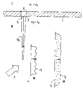
Fig. l shows schematic diagrams of four states I, II, III
and IV of the reactive mixture. After mixing the components
of the reactive mixture in a suitable mixing apparatus, the
mixture enters a distribution chamber indicated by wall l~
It is then in state I, at a pressure which is greater than
or at least equal to the saturation pressure of the
dissolved carbon dioxide. The saturation pressure of carbon
dioxide, for a carbon dioxide content of 3 ~, is about 7.5
bar. The pressure in the distribution chamber in state I is
there~ore greater than or equal to 7.5 bar. It may be e.g.
8 to 12 bar. Wall l of the distribution chamber has an
opening 2 with a small cross-sectional ~lmension d in at
least one direction. On the other side of opening 2 a
pressure PII prevails, which is less than the saturation
pressure of the dissolved CO2, preferably approximately
atmospheric pressure of l - 2 bar absolute. Due to the
pressure difference between the two sides of opening 2, the
reactive mixture is forced through the opening with the
production o~ high shear forces. At the exit from opening
2, the velocity profile V0 at time to of reactive mixture
emerging from opening 2 via dimension d is shown (state
II). Within a short time, during which still essentially no
carbon dioxide is released from the reactive mixture now
supersaturated with carbon dioxide, the stream of reactive
mixture emerging from opening 2 is turned through an angle
CA 02205870 1997-05-22
WO 96/16782 PCT/I~;P95~04492
19
as indicated by functional arrow 3 and the speed is
reduced, wherein the reactive mixture still containing
dissol~ed carbon dioxide is converted into state III, which
is drawn in the form of a diagrammatic velocity profile v
over the width of the flow of reactive mixture at time tl
a~ter being deflected. Finally, in state IV, the dissolved
carbon dioxide is released with the formation of bubbles.
Fig. 2 shows a section through the device for producing
foam according to the invention which is shown in
perspective in Fig. 2a. The reactive mixture is introduced
into the extended distribution chamber 11 from the mixing
head (not shown) via pipe 10. The opening with a small
dimension is in the form of an extended slit 12 at right
angles to the plane of the drawing in Fig. 2. A stream of
reactive mixture in the form of a sheet, indicated by arrow
II, emerges from slit 12 at right angles to the plane of
the drawing and impinges on impact surface 13 facing slit
12. The high rate of flow of the reactive material is
thereby turbulently reduced. The volume of the deflection
chamber 14 is selected so that the residence time produced
for the reactive mixture therein is such that carbon
dioxide is essentially still not released during this time.
Only after the reactive mixture emerges from the deflection
volume 14 is carbon dioxide released therefrom with the
formation of foam 15.
An improved turbulent reduction in the high exit speed of
the reactive material from slit 12 is achieved when
boundary edges 16 and 17 for the deflection chamber 14 are
provided in accordance with Fig. 3. Otherwise the drawing
in accordance with Fig. 3 corresponds to that in accordance
with Fig. 2.
CA 0220~870 1997-0~-22
WO 96/16782 PCT/~ 5slo1192
Fig. 4 shows a foam-forming device according to the
invention in which deflection chamber 14 is restricted by
perforated plate 18 as a flow-stabilising element.
Fig. 5 shows a device which is analogous to the preceding
figures, wherein a perforated plate 22 is provided as an
element for producing high rates of shear. The stabilising
sieve 18 is used, as is shown in Fig. 5a, which is an
enlarged detail UA" from Fig. 5, both as an impact surface
and for stabilising the flow of the reactive mixture. Fig.
5b shows the material flows fanning out due to the widening
contours on the exit side of the passageways.
Fig. 6 shows a device for producing foam according to the
invention with circular symmetry with an annular slit 12
for producing the high rates of shear. The upper boundary
of annular slit 12 is formed by a central body 30 which is
surrounded by a circular distribution chamber 11. Circular
chamber 11 is sealed tightly against housing 35 by means of
a piston 32 connected to the central body 30. Piston 32 can
be moved vertically to adjust the width of the annular slit
12 by introducing a hydraulic liquid 34 into space 31 above
piston 32. Piston 32 can also be provided with a guide
piston 33 for preventing piston 32 from tilting in
housing 35.
Fig. 7 shows a unit for producing slabs of foam. The polyol
component 41, the isocyanate component 42 and other
auxiliary agents and additives are supplied to the m;x;ng
apparatus 40 via piping 43. The polyol component 41
preferably contains carbon dioxide dissolved under
pressure. From the mixing apparatus 40, the now mixed
components are introduced into distribution chamber 11 of
the foam-forming device 44. Foam-forming unit 44 shown as
CA 0220~870 1997-0~-22
WO 96116782 PCT/~ S104q92
21
an example corresponds to the drawing in accordance with
Fig. 6. The foam 15 emerging from foam-forming device 44 is
deposited on a lower laminating film 51 which is moved away
from the foam-forming device 44 on a conveyer belt 50.
Furthermore, an upper laminating film 52 may be supplied
from above.
Fig. 8 contains an alternative proposal for a foam-forming
device according to the invention with an extended,
adjustable slit. Here, the boundary surface of slit 12 is
formed by an elastic polymer tube 80 which can be
pneumatically or hydraulically expanded to adjust slit 12.
Fig. 8a shows a section A-A through Fig. 8. Fig. 8
represents a section B-B through Fig. 8a.
Figs. 9 and 9a show a cross-section and longitudinal
section through a foam device according to the invention,
in which 4 foam devices a, b, c and d, as shown in
principle in Fig. 5, are integrated in the form of a
magazine in an essentially cylindrical carrier 61. The
carrier 61 is arranged so that it can rotate about an axis
in a cylindrical cage 62. The cylindrical cage 62 has an
opening 63 along a line in the jacket parallel to the axis
through which the foam can emerge from the particular foam
device which is in operation. Furthermore, the distribution
channel 11 associated with the particular foam device in
operation (in the drawing foam device a) is filled with
reactive mixture via feed pipe 10 which passes into
cage 62. Furthermore, feed pipes 64 are provided to at
- 30 least one of the foam devices not in operation (b, c and/or
d) which are enclosed in cage 62, and cleaning liquid is
supplied through these. Corresponding discharge channels 65
are provided for the cleansing liquid. The foam device
magazine shown in figs. 9 and 9a enables the foam device to
CA 0220~870 1997-0~-22
WO 96/16782 ~ 75/04492
be changed in the shortest possible time during operation,
if the perforated plate 22 of the foam device in operation
is blocked by foreign particles from the polyurethane
reactive mixture or by polyurethane which has hardened on
the wall of the piping and then been dislodged. The rinsing
out liquid (usually polyol) is preferably passed in the
opposite direction (as compared with the reactive mixture
during the foaming process) through the foam device which
is not in operation.
In order to achieve the operational states "foaming" and
''rinsing with cleansing liquid" it would be sufficient to
provide a magazine with only 2 foam devices. According to
the invention, however, 4 to 12 foam devices are preferably
integrated in one magazine, wherein the foam devices differ
with regard to the diameter of the holes in perforated
plates 18 and 22 and/or the number of holes (free passage
area), pairs of foam devices being designed to be
identical. In this way, an optimally adapted foaming device
may be selected for the particular reactive mixture
(viscosity, temperature, carbon dioxide content) at the
start of the operation and then expansion may be performed
alternately with this and the foam device which is
identical to it. Fig. 9 indicates that the spacers 66
between perforated plates 22 and 18 may be constructed as
diaphragms which restrict the effective cross-section of
perforated plates 18 and 22. In the embodiment shown, the
effective cross-section in foam devices c and d is reduced
as compared with foam devices a and b by diaphragms 66. The
effective cross-section of perforated plate 22 can
typically be between 3 and 15 mm (cross-sectional size in
accordance with Fig. 9) and the longitudinal extension of
perforated plate 22 can be between 150 and 800 mm
(longitudinal size in accordance with Fig. 9a).
CA 02205870 1997-05-22
WO 96/16782 P~ S/Q~q92
Figs. 10 and lOa show a magazine of foam devices according
to the invention, analogous to figs. 9 and 9a, wherein only
two foam devices a and b are provided. The supply 10 of the
reactive mixture does not take place via the head of the
cylindrical cage 62, in contrast to the embodiment in Fig.
9a, but in the middle of the longitudinal length of the
cylindrical cage so that the flow routé for the reactive
mixture in distribution channel 11 only stretche~ over half
the longitudinal length of the cylindrical cage. According
to the invention, the spacer 66 between perforated plates
22 and 18 is designed to be a continuously adjustable
diaphragm in the embodiment in accordance with figs. 10 and
lOa, so that the effective areas of perforated plates 22
and 18 can be continuously modified. This is explained in
more detail in figs. lOb and lOc. Fig. lOb shows a section
B-B through the diagram in accordance with figs. 10 and lOa
so that diaphragm 66 can be viewed (after removal of
perforated plate 18). The spacer 66 between perforated
plates 18 and 22 consists of 3 sections, 66a, 66b and 66c,
which cover perforated plate 22 in the diagram in Fig. lOb
except for the visible e~fective cross-section. Spacer
sheets 66a and 66c are fixed in place. They are screwed
against the cylindrical body 61 together with perforated
plates 22 and 18 and take the pressure of the reactive
mixture on perforated plate 22. The adjustable section of
the diaphragm, 66b, and spacer plate 66a have saw-tooth
shaped sliding surfaces 69 which shift the edge of the
diaphragm 70 of diaphragm 66b transversely over perforated
plate 22 when moved in the direction of arrow 71. Diaphragm
66b has extensions which can be moved and which project out
of the cylindrical body 61 at the angle of sliding surfaces
69 and are connected to screw 73. Screw 73 is guided inside
a casing 72 and can be moved in the direction of arrow 71
by means of nut 74. Spacer sheets 66a and 66c may have a
CA 0220~870 l997-0~-22
WO96/16782 PCT/~5~/0~492
24
thickness of 0.5 to 4 mm, preferably 1 to 2 mm, according
to the invention. The moveable diaphragm 66b preferably has
a thickness which is 0.01 to 0.05 less than that. The
foaming process is preferably started with the largest
possible effective area for perforated plate 22 and as it
progresses, the effective area of perforated plate 22 iS
continuously decreased until an optimum foam structure is
obtained.
~rle
A unit according to Fig. 7 is used for the production of
polyurethane foam. The conveyor belt speed is 7 m/min.
The width of the conveyor belt is 2 m, the distance between
the upper laminating film 52 and the lower laminating film
51 is 1. 2 m. Instead of foam-forming device 44 a foam-
forming device according to Fig. 5 iS used. The perforated
plates 22 and 18 each formed an area not covered by flanges
and supports of 1.3 cm in width and 70 cm in length. The
thickness of the perforated plates was in each case 0. 2 mm.
Per cm2the perforated plate 22 had 256 perforations each of
a diameter of 0.1 mm on the inlet side, which widened to
approximately 2.5 times the diameter in the direction of
flow. The free throughflow area of all the per~orations
was about 1. 82 cm2.
The distance between the perforated plate 18 (stabilisation
grid) and the perforated plate 22 was 1 mm. Per cm2 it had
3000 holes each of a diameter of 0.1 mm on the inlet side
which widened to 2.5 times the diameter.
In the mixing apparatus 40 (Fig. 7) an expandable reactive
mixture of the following composition is produced:
CA 02205X70 1997-05-22
WO 96/16782 PcT/~;l J~J~92
100 parts by weight of a polyether polyol with an OH
number of 45, containing 8S% by weight of propylene
oxide units and 15% by weight of ethylene oxide units,
initiated with trimethylolpropane,
4.2 parts by weight of water,
4.0 parts by weight o~ CO2,
1.3 parts by weight of a silicone stabiliser,
O.15 parts by weight of an amine catalyst,
0.16 parts by weight of tin octoate and
parts by weight of toluylene diisocyanate 80/20.
The polyol, water and liquid CO2 are pre-mixed in a static
mixer at 70 bars, the pressure of the mixture is reduced to
15 bar and it is introduced via feed line 41 into m; ~; ng
apparatus 40, in which it is mixed with the isocyanate and
the other additives.
The pressure at the exit to the mi ~i ng chamber was 11 bars.
270 kg o~ reactive mixture were conveyed per minute. The
rate of shear as the mixture passes through the perforated
plate 22 (Fig. 5) is calculated to be 1.3 106/sec.
The reactive mixture foamed as it issued from the foam-
forming device in the form of a stable, greatly expanding
froth, which spread over the conveyor belt. Only a few
meters downstream of the point of deposition on the
conveyor belt the froth began to rise due to the reaction
of the water with the isocyanate. After about 12 m the
mA~imum slab height of 1.2 m was reached.
A foam slab with a density of 16.1 kg/m3 was obtained.
CA 02205870 1997-05-22
WO 96tl6782 PcT/~;l 9S/~ 92
26
The foam was open-pored and had 16 to 19 pores per cm. It
was substantially free of voids and pores with diameters
higher than 2 mm.