Language selection

Search

Patent 2205913 Summary

Third-party information liability

Some of the information on this Web page has been provided by external sources. The Government of Canada is not responsible for the accuracy, reliability or currency of the information supplied by external sources. Users wishing to rely upon this information should consult directly with the source of the information. Content provided by external sources is not subject to official languages, privacy and accessibility requirements.

Claims and Abstract availability

Any discrepancies in the text and image of the Claims and Abstract are due to differing posting times. Text of the Claims and Abstract are posted:

  • At the time the application is open to public inspection;
  • At the time of issue of the patent (grant).
(12) Patent Application: (11) CA 2205913
(54) English Title: SNOWBOARD BINDING WITH RELEASE MECHANISM
(54) French Title: ATTACHE DE PLANCHE A NEIGE AVEC MECANISME DE LIBERATION
Status: Deemed Abandoned and Beyond the Period of Reinstatement - Pending Response to Notice of Disregarded Communication
Bibliographic Data
Abstracts

English Abstract


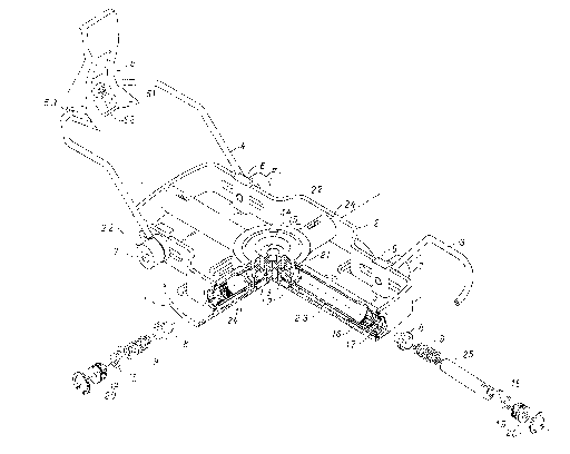
Releasable snowboard binding which includes upper complex (2) where therear boot holder (3) and front root holder (4) are fastened with screws (7) and
nuts (6) to the buckle (5), allowing adjustment at the same time. On the
central ring (2.1) tubular elements (2.3) and (2.4) are welded and set at 90
degrees distance, all encircled with four identical elements (2.2) and welded
together. Each tubular element includes pressing bolt (8) pushed by spring
(9) then tense display (18) and tense screw (19). Tubular elements (2.3)
include additional distance part (25) between spring (9) and tense display
(18). All pressing bolts (8) fit precisely into recesses in the upper ring (1.4)of lower complex (1), set at 90 degrees distance. The upper ring (1.4) is
tigtened with screw (1.5) to the lower ring (1.2) to friction ring (1.3)
in-between them. The lower ring (1.2) is welded to attaching plate (1.1),
fastened by screws to the snowboard.


French Abstract

Attache de planche à neige avec mécanisme de libération comprenant un complexe supérieur (2) sur lequel une fixation de botte (3) et une fixation de racine avant (4) sont assujetties au crochet (5) au moyen de vis (7) et d'écrous (6) qui permettent en même temps le réglage. Sur l'anneau central (2.1), des éléments tubulaires (2.3) et (2.4) sont soudés et disposés à 90 degrés l'un de l'autre, encerclés par quatre éléments identiques (2.2) et soudés ensemble. Chaque élément tubulaire comprend un boulon à pression (8) poussé par un ressort (9) puis un affichage de tension (18) et une vis de tension (19). Les éléments tubulaires (2.3) comportent une pièce additionnelle d'espacement (25) entre le ressort (9) et l'affichage de tension (18). Tous les boulons à pression (8) s'ajustent avec précision dans les logements de l'anneau supérieur (1.4) du complexe inférieur (1), disposés à 90 degrés l'un de l'autre. L'anneau supérieur (1.4) est serré par une vis (1.5) contre l'anneau inférieur (1.2) et un anneau à friction (1.3) entre les deux. L'anneau inférieur (1.2) est soudé à une plaque de fixation (1.1) assujettie à la planche à neige au moyen de vis.

Claims

Note: Claims are shown in the official language in which they were submitted.

CLAIMS
1. Releasable snowboard binding, consisting of rear boot holder (3), front
boot holder (4) with buckle (5) is designed so that boot holders are fastened
with screws (7) and nuts (6) to supporting part of upper complex (2) where it
can move longitudinally inside slots on outer frame (2.2).
2. Releasable snowboard binding from the point 1 hereof is designed so
that stated supporting complex (2) includes two shorter tubular members
(2.4), and two longer tubular members (2.3) placed on the central ring (2.1)
with 90 degrees distance between them, all framed with four identical frame
elements (2.2).
3. Releasable snowboard binding from the point 2 hereof is designed so
that each tubular member (2.4) includes pressing bolt (8) pushed by spring
(9), having tense display (18) and tense screw (19) all limited by safety ring
(20).
4. Releasable snowboard binding from the point 2 and 3 hereof is
designed so that each tubular member (2.3) includes additional distance part
(25) placed in-between spring (9) and tense display (18)
5. Releasable snowboard binding from the point 2 hereof is designed so
that its central ring (2.1) surrounds the upper ring (1.4) which has four
concave recesses, placed at 90 degrees distance in horizontal plane, where
fitting precisely the bowl head of pressing bolt (8).
6. Releasable snowboard binding from the point 5 hereof is designed so
that under the upper ring (1.4) of complex (1) friction ring (1.3) is placed,
leaning against the surface of lower ring (1.2), welded with its other surface
to attaching plate (1.1).
7. Releasable snowboard binding from the point 6 hereof is designed so
that all members of complex (1) are fastened with screw (1.5) into compact
unit.

Description

Note: Descriptions are shown in the official language in which they were submitted.


CA 02205913 1997-05-26
.
Legalized translation from Croatian
Dinko Starcevic
S. V. (~ice 8
T. 51000 Rijeka
U. Croatia
SNOWBOARD BlNDING WITH RELEASE MECHANISM
INVENTlON DESCRIPTION
1) Tl~C~NIC~L ARI~A CORRESPONDING TO THE INVENTION
This invention relates to ski bindings as wide area in consideration of
snowboard bindings as a very speci~tc technical field. According to the
International Patent Classification it is classifed as:
2) TEC~INICAL DEMAND
Being engaged in sport called snowboarding there still exists essential risk:
how to protect efficiently legs from serious injuries or fractures. Directly to
that problem we are also faced with the possibility of an undesirable effect:
releasing of the binding at harder board carving or harder board sl~rnming to
the slope, avoiding snowboarder's fall.
3) STATl~ OF THE PRIOI~ ART
All l~nown solutions are mainly based on principle of fLYcd connection
between the snowboarder and snowboard, which means that when the
snowboarder falls down, he will not be separated from the board. Bindings
are divided into two known categories: soft and hard type, where only the
hard ones have couple models with insuf~lcient ability of releasing at the
moment of fall. So, all circumstances are reduced to fixed bindings use,
which have no release characteristics, meaning that there is great risk fior
snowboarders to hurt their legs.

CA 02205913 1997-05-26
.
4) IlWENTION ESSENCE EXPLICATION
Primarily, the goal of this invention is to enable safe binding to
snowboarders, allowing maximunn protection and reduction to the minimum
of risk factors.
The second aim is to put in use longer snowboards, which has been almost
impossible so far, due to fixed attachment to the board, and extremely high
~ risk of accidents
The next aim is to endure such binding which will be able to release the foot
only in critical moment of overloading or fall, but at the same time to achieve
compact and solid attachment to the board.
Further aims and advantages of this invention will be partly reviewed in the
following description and partly through invention use. Releasable
snowboard binding includes tWQ main complexes of elements: lower
complex attached with screws to the board, which intrudes with its ring-
shaped parts into the upper complex, achieving mechanical connection wi~h
the same, then the upper complex having the boot attached over its top,
encircling partly the lower complex. Elements of the upper complex as well
as the lower one are fastened together by welding joints where maximum
stiffness is achieved, then screw joints which allow several regulations and
adjustments. The essence of the invention is mechanical joint which
disconnects, releases, at overloaded force and establishes again by simple
pressing the upper complex over the top of the ring-shaped parts of the lower
complex.
5) DRAWINGS DESCRIlPTION
The folIowing drawings, being the part of invention description, illustrate in
the best way so far the invention performance and are very helpful for
explanation of basic invention principles.

- CA 0220'7913 1997-05-26
.
Figure I Spatial perspective of releasable snowboard binding in state of
complete assembly with cut of one symmetric quarter for better
layout of smaller elements
Figure 2 Spatial pcrspective of supporting part of upper complex (2) with
its elements which are welded together.
Figure 3 Spatial perspective of lower complex (13 with its compositlg
elements, where ~ and (1.2~ are welded together and attached
with screw joint to other parts
Figure 4 Spatial perspective of front boot holder
Figure 5 Spatial perspective of rear boot holder
Figure 6 Spatial perspective of holder of rubber support
Figure 7 Spatial perspective of rubber support
Figure 8 Spatial perspective of screw for booth holders
Figure 9 Spatial perspective of nut for boot holders attachment
Figure 10 Spatial perspective of all elements of upper complex in order of
installing in tubular elements (2.3) and (2.4)
Figure 11 Spatial perspective of buckle of front lboot holder
6~ DETAILED DI~SCRII'TION OF AT LEAST ONE ~IANNER OF
INVENTION PElRFORMANCES
Introduction into detailed performance of this invention is presented here
below, along with an example illustrated on attached drawings.
Referring to Fig. 1 it can be seen that releasable snowboard binding includes
two main complexes, I and 2, which have all other functionalk indispensable
elements attached. Lower complex 1, includes attaching plate 1.1 with screw

CA 02205913 1997-05-26
.
holes and lower ring 1.2 welded to the plate. Friction ring 1.3 and upper ring
1.4 with four concave recesses set at 90 degrees distance in the horizontal
plane, all fastened together with screw 1.5 to the lower ring, all shown on the
Fig. 3. Upper complex 2, visible on Fig. 2, encircles its central ring 2.1 the
lower complex, is made from two tubular elements 2.3, two tubular elements
2.4 and the frame from four identical elements 2.2. All tabular elements are
set at 90 degrees distance in horizontal plane, precisely opposite to concave
recesses in the element 1.4 of lower complex. Tubular elements contain
inside alI indispensable parts to achieve direct mechanical connectivn of
upper and lower complex, beginning with pressing bolt 8, which precisely
fits into the recess in element 1.4, then spring ~, tense display 18 and tense
screw, all visible on Fig. 10. In two longer tubular elements 2.3 distant part
25 is placed in-between the spring and tense display. In all b~bular elements
2.3 and 2.4 there is safety ring 20 placed in its groove, just at the outer ends.
Rear boot holder 3 is placed on the upper complex 2, as well as the front boot
holder 4 with the buckle 5, all fastened together with screws 7 and nuts 6 in
the element regulation slots 2.2. The whole upper complex is leaning with its
ends on h~o rubber supports 17, which are fastened to their holders 16. As
shown on Fig. 1, 2, 3 and 5, this invention offers technical feasibility making
it possible that snowboarder's boot, attached to the upper complex, can be
released from the lower complex attached to the board. Boot sole is leaning
onto supporting part 2, being restraint in-between the rear boot holder 3 and
the buckle 5 on front boot holder. Required length is set up, as show~ on Fig.
1, with screws 6 and rluts 7, pushing along slots. Mechanical connection
between upper and lower complex is achieved by elements shown on rlg. 10,
placed in tubular elements 2.3 and 2.4 put in Ihe same order, where
tightening or loosing of the tense screw 19 is increasing or decreasing
releasing force respectively. If connection is displaced in the of fall, or
detaching the two complexes, then with very simple vertical pressing of
complex 2 over the upper ring 1.4, connection is restituted by dropping
pressing bolts into their recesses on the upper ring. ~s shown on Fig. 3,
friction ring is placed under the ring 1.4 and tightened with screw 1.5 and
achieves solid joint, but at the same time with loosing the crew it allows
horizontal twist adjustment in any desirable position.
For production of binding hard plastic is recommended for buckle 5 and distance
part 25, hard rubber for rubber support 17 and friction ring 1.3, and inox steel for
all the other parts. The length of binding or supporting complex 2 should not
exceed 200 mm, while the thickness should be 20 mm

CA 02205913 1997-05-26
.
12) MODE OF II~VENTIOl~ APPLYING
This invention provides maximum snowboarding safety and opens new
potentials even in snowboard production: because of safety reasons a most
common length of snowboard is 1.4 m to 1.5 m, but never more than 1.7 m.
Now these limits may be moved towards bigger lengths which allow
smoother and more stable ride, very alike skiing.
~ Likewise it is possible to attach soft snowboard binding over the top, and
reunion advantages of soft binding with ma~imurn safety.

Representative Drawing
A single figure which represents the drawing illustrating the invention.
Administrative Status

2024-08-01:As part of the Next Generation Patents (NGP) transition, the Canadian Patents Database (CPD) now contains a more detailed Event History, which replicates the Event Log of our new back-office solution.

Please note that "Inactive:" events refers to events no longer in use in our new back-office solution.

For a clearer understanding of the status of the application/patent presented on this page, the site Disclaimer , as well as the definitions for Patent , Event History , Maintenance Fee  and Payment History  should be consulted.

Event History

Description Date
Inactive: IPC deactivated 2012-01-07
Inactive: IPC expired 2012-01-01
Inactive: First IPC from PCS 2012-01-01
Inactive: IPC from PCS 2012-01-01
Time Limit for Reversal Expired 2000-05-26
Application Not Reinstated by Deadline 2000-05-26
Amendment Received - Voluntary Amendment 1999-08-26
Deemed Abandoned - Failure to Respond to Maintenance Fee Notice 1999-05-26
Application Published (Open to Public Inspection) 1998-11-26
Classification Modified 1997-08-19
Inactive: First IPC assigned 1997-08-19
Inactive: IPC assigned 1997-08-19
Inactive: Filing certificate - No RFE (English) 1997-07-28
Filing Requirements Determined Compliant 1997-07-28
Inactive: Office letter 1997-07-25
Application Received - Regular National 1997-07-25

Abandonment History

Abandonment Date Reason Reinstatement Date
1999-05-26

Fee History

Fee Type Anniversary Year Due Date Paid Date
Application fee - small 1997-05-26
Owners on Record

Note: Records showing the ownership history in alphabetical order.

Current Owners on Record
STARCEVIC DINKO
Past Owners on Record
None
Past Owners that do not appear in the "Owners on Record" listing will appear in other documentation within the application.
Documents

To view selected files, please enter reCAPTCHA code :


To view images, click a link in the Document Description column. To download the documents, select one or more checkboxes in the first column and then click the "Download Selected in PDF format (Zip Archive)" or the "Download Selected as Single PDF" button.

List of published and non-published patent-specific documents on the CPD .

If you have any difficulty accessing content, you can call the Client Service Centre at 1-866-997-1936 or send them an e-mail at CIPO Client Service Centre.


Document
Description 
Date
(yyyy-mm-dd) 
Number of pages   Size of Image (KB) 
Abstract 1997-05-26 1 56
Description 1997-05-26 5 230
Claims 1997-05-26 1 51
Drawings 1997-05-26 5 149
Cover Page 1998-11-30 2 81
Representative drawing 1998-11-30 1 24
Filing Certificate (English) 1997-07-28 1 164
Notice: Maintenance Fee Reminder 1999-03-01 1 119
Courtesy - Abandonment Letter (Maintenance Fee) 1999-06-23 1 186
Second Notice: Maintenance Fee Reminder 1999-11-29 1 119
Notice: Maintenance Fee Reminder 2000-02-29 1 121
Correspondence 1997-07-29 1 17