Language selection

Search

Patent 2206169 Summary

Third-party information liability

Some of the information on this Web page has been provided by external sources. The Government of Canada is not responsible for the accuracy, reliability or currency of the information supplied by external sources. Users wishing to rely upon this information should consult directly with the source of the information. Content provided by external sources is not subject to official languages, privacy and accessibility requirements.

Claims and Abstract availability

Any discrepancies in the text and image of the Claims and Abstract are due to differing posting times. Text of the Claims and Abstract are posted:

  • At the time the application is open to public inspection;
  • At the time of issue of the patent (grant).
(12) Patent: (11) CA 2206169
(54) English Title: A BIT RETENTION DEVICE FOR A BIT AND CHUCK ASSEMBLY OF A DOWN-THE-HOLE PERCUSSIVE DRILL
(54) French Title: DISPOSITIF DE RETENU POUR TREPAN ET DISPOSITIF D'AJUSTEMENT POUR FORAGE MIS EN OEUVRE AU FOND DU TROU
Status: Expired and beyond the Period of Reversal
Bibliographic Data
(51) International Patent Classification (IPC):
  • E21B 10/36 (2006.01)
  • E21B 01/00 (2006.01)
  • E21B 04/06 (2006.01)
  • E21B 17/07 (2006.01)
(72) Inventors :
  • JONES, WILLIAM LESLIE (United States of America)
(73) Owners :
  • ATLAS COPCO SECOROC LLC
(71) Applicants :
  • ATLAS COPCO SECOROC LLC (United States of America)
(74) Agent: NORTON ROSE FULBRIGHT CANADA LLP/S.E.N.C.R.L., S.R.L.
(74) Associate agent:
(45) Issued: 2005-11-22
(22) Filed Date: 1997-05-26
(41) Open to Public Inspection: 1997-12-10
Examination requested: 2002-05-24
Availability of licence: N/A
Dedicated to the Public: N/A
(25) Language of filing: English

Patent Cooperation Treaty (PCT): No

(30) Application Priority Data:
Application No. Country/Territory Date
08/662,725 (United States of America) 1996-06-10

Abstracts

English Abstract

A bit retention device for a bit and chuck assembly of a down-the-hole, percussive drill, for retaining a head section of a bit should the head section separate from a shank of the bit includes a chuck adapted for threadable connection to a drill casing, a drill bit, a bit retaining shoulder in the the assembly; a wear collar concentric about the chuck and bit and a flexible retaining member removably connected to the assembly, the retaining member extending radially between the wear collar and bit a sufficient distance to contact the retaining shoulder should the bit drop axially downwardly.


French Abstract

Un dispositif de rétention de trépan pour un ensemble de trépan et de mandrin d'une foreuse fond de trou à percussion, pour retenir une partie de tête d'un trépan si la partie de tête se sépare d'une tige du trépan, comprenant un mandrin adapté pour être raccordé par vissage à un tubage de foreuse, un trépan de foreuse, un épaulement de retenue de trépan dans l'ensemble ; une bague d'usure concentrique au mandrin et au trépan et un élément de retenue flexible relié de manière amovible à l'assemblage, l'élément de retenue s'étendant radialement entre la bague d'usure et le trépan d'une distance suffisante pour communiquer avec l'épaulement de retenue si le trépan tombe axialement vers le bas.

Claims

Note: Claims are shown in the official language in which they were submitted.

The embodiments of the invention in which an exclusive
property or privilege is claimed are defined as follows:
1. A bit retention device for a bit and chuck assembly
of a down-the-hole, percussive drill, for retaining a
head section of a bit should the head section separate
from a shank of the bit comprising:
(a) a cylindrical chuck adapted for threadable
connection to a drill casing, said chuck terminating in a
radially extending lower end face surface;
(b) bit retaining shoulder means in said assembly
for forming a radially extending bit retaining shoulder;
(c) a drill bit comprising:
(i) an axially extending shank in driving
engagement with said chuck, said shank terminating in a
radially extending driving shoulder, said driving
shoulder having an upper surface facing said end face
surface of said chuck;
(ii) a bit head having a working bit face: and
(iii) an upper bit head portion adjacent to
said retaining shoulder, said upper bit head portion
extending axially along said bit head, said upper bit
head portion having a radial diameter that is smaller
than a radial diameter of said retaining shoulder;
(d) a wear collar of hollow cylindrical form
concentric about a lower portion of said chuck and said
upper bit head portion;
(e) a flexible retaining member removably connected
to said assembly, said retaining member positioned within
said wear collar, said retaining member positioned
axially between said chuck end face surface and said bit
working face, said retaining member extending radially
between said wear collar and said upper bit head portion
a sufficient distance to contact said retaining shoulder
should said bit drop axially downwardly, whereby said
drill bit is movable axially within said chuck, but
-7-

retained within said chuck by said retaining shoulder and
said retaining member; and
(f) aperture means in said wear collar for
permitting access to said retaining member by an
adjustment tool.
2. A bit retention device for a bit and chuck assembly
of a down-the-hole, percussive drill, for retaining a
head section of a bit should the head section separate
from a shank of the bit comprising:
(a) a cylindrical chuck adapted for threadable
connection to a drill casing, said chuck terminating in a
radially extending lower end face surface;
(b) a drill bit comprising:
(i) an axially extending shank in driving
engagement with said chuck, said shank terminating in a
radially extending driving shoulder, said driving
shoulder having an upper surface facing said end face
surface of said chuck;
(ii) a bit head having a working bit face;
(iii) an upper bit head portion adjacent to
said driving shoulder forming a radially extending bit
retaining shoulder, said retaining shoulder having a
lower surface facing said bit working face; and
(iv) an annular undercut head portion adjacent
to said retaining shoulder, said annular undercut portion
extending axially along said bit head, said undercut
portion having a radial diameter that is smaller than a
radial diameter of said retaining shoulder;
(c) a wear collar of hollow cylindrical form
concentric about a lower portion of said chuck, said bit
retaining shoulder and said annular undercut portion; and
(e) a flexible retaining member removably connected
to an inner surface of said wear collar, said retaining
member positioned axially between said retaining shoulder
and said bit working face, said retaining member
-8-

extending radially between said wear collar and said bit
head a sufficient distance to stop said retaining
shoulder should said bit drop axially downwardly, whereby
said drill bit is movable axially between said chuck end
face and said retaining member, but retained within said
chuck by said retaining shoulder and said retaining
member.
3. The bit retention device of claim 2 wherein said
retaining member is a flexibly expandable and
contractible split ring
removably positioned in an annular groove in said wear
collar inner surface.
4. The bit retention device of claim 3 further
comprising: aperture means in said wear collar for
permitting access to said retaining member by an
adjustment tool.
5. A bit retention device for a bit and chuck assembly
of a down-the-hole, percussive drill, for retaining a
head section of a bit should the head section separate
from a shank of the bit comprising:
(a) a cylindrical chuck adapted for threadable
connection to a drill casing, said chuck terminating in a
radially extending lower end face surface;
(b) a drill bit comprising:
(i) an axially extending shank in driving
engagement with said chuck, said shank terminating in a
radially extending driving shoulder, said driving
shoulder having an upper surface facing said end face
surface of said chuck;
(ii) a bit head having a working bit face and
an upper bit head portion;
(iii) a first annular groove in said upper bit
head portion adjacent to said driving shoulder having an
-9-

outer surface with an annular groove therein; and
(iv) a second annular groove in said upper bit
head portion axially below said first annular groove,
said first annular groove having a radial diameter that
is smaller than a radial diameter of second annular
groove;
(c) a wear collar of hollow cylindrical form
concentric about a lower portion of said chuck, said
first and second annular bit grooves, said wear collar
having a radially extending bit retaining shoulder, said
retaining shoulder having an upper surface facing said
annular bit groove; and
(e) a flexible retaining member removably positioned
in said second bit annular groove, said retaining member
positioned axially between said drive shoulder and said
bit working face, said retaining member extending
radially between said wear collar and said bit head a
sufficient distance to stop said bit should said bit drop
axially downwardly, whereby said drill bit is movable
axially between said chuck end face and said retaining
member, but retained within said chuck by said retaining
shoulder and said retaining member.
6. The bit retention device of claim 5 wherein said
retaining member is a flexibly expandable and
contractible split ring
removably positioned in said annular groove.
-10-

Description

Note: Descriptions are shown in the official language in which they were submitted.


CA 02206169 1997-09-03
A BIT RETENTION DEVICE FOR A BIT AND CHUCK ASSEMBLY OF A
DOWN-THE-HOLE, PERCUSSIVE DRILL
BACKGROUND OF THE INVENTION
This invention relates generally to down-the-hole,
percussive drills, and more particularly to retention
devices for retaining a head section of a bit should the
1o head section separate from a shank of the bit.
In percussion downhole drilling, broken bits are a
common occurrence because of the severe impact and
rotational loads necessary to accomplish the drilling
effect. Failures in the shank result in the head portion
of the bit remaining in the hole. Time consuming and
expensive procedures are required to remove the head
before drilling can continue. If the head cannot be
removed, the hole must be abandoned.
It is common practice to provide external " fishing "
2o threads on the rear portion of the bit head to facilitate
removal of the broken bit head by use of an internally
threaded "fishing " tool. This is a somewhat difficult
separate operation and results are very often futile.
Therefore it would be very advantageous to provide a
system where the broken portion of the bit is
automatically retrieved with the drill string and hammer.
One device for this purpose as described in U.S.
Patent No. 5,065,827 (Meyers, et. al.). This device
includes an attachment piece with internal threads and a
3o corresponding external thread on the bit. Such devices
have several disadvantages. The threaded engagement may
be lost if reverse rotation occurs after bit failure,
resulting in bit head loss. Meyers suggests that a pin
may be installed to prevent this, but this complicates
removal even more. Also, if the threads are damaged in
normal drilling, the removal of an unbroken bit for
- 1 -

CA 02206169 1997-09-03
sharpening or other service is difficult or impossible
without destroying the device.
The foregoing illustrates limitations known to exist
in present drill bit retention devices. Thus, it is
apparent that it would be advantageous to provide an
alternative directed to overcoming one or more of the
limitations set forth above.
Accordingly, a suitable alternative is provided
1o including features more fully disclosed hereinafter.
SUMMARY OF THE INVENTION
In one aspect of the present invention, this is
accomplished by providing a bit retention device for a
bit and chuck assembly of a down-the-hole, percussive
drill, for retaining a head section of a bit should the
head section separate from a shank of the bit includes a
cylindrical chuck adapted for threadable connection to a
drill casing, the chuck terminating in a radially
2o extending lower end face surface; bit retaining shoulder
means in the assembly for forming a radially extending
bit retaining shoulder; a drill bit including: an axially
extending shank in driving engagement with the chuck, the
shank terminating in a radially extending driving
shoulder, the driving shoulder having an upper surface
facing the end face surface of the chuck; a bit head
having a working bit face; and an upper bit head portion
adjacent to the retaining shoulder, the upper bit head
portion extending axially along the bit head, the upper
3o bit head portion having a radial diameter that is smaller
than a radial diameter of the retaining shoulder; a wear
collar of hollow cylindrical form concentric about a
lower portion of the chuck and the upper bit head
portion; a flexible retaining member removably connected
to the assembly, the retaining member positioned within
the wear collar, the retaining member positioned axially
- 2 -

CA 02206169 1997-09-03
between the chuck end face surface and the bit working
face, the retaining member extending radially between the
wear collar and the upper bit head portion a sufficient
distance to contact the retaining shoulder should the bit
drop axially downwardly, whereby the drill bit is movable
axially within the chuck, but retained within the chuck
by the retaining shoulder and the retaining member; and
aperture means in the wear collar for permitting access
to the retaining member by an adjustment tool.
15
The foregoing and other aspects will become apparent
from the following detailed description of the invention
when considered in conjunction with the accompanying
drawing figures.
BRIEF DESCRIPTION OF THE DRAWING FIGURES
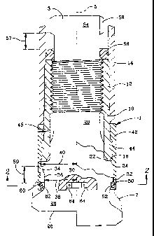
Fig. 1 is a schematic, longitudinal, cross-sectional view
of the device according to the invention, with a prior
2o art bit head working end shown in phantom, an unbroken
bit depicted to the left of the centerline and a broken
bit to the right of the centerline;
Fig. 2 is a view along 2-2 of Fig. l;
Fig. 3 is a schematic, longitudinal, cross-sectional view
of an alternate embodiment of the invention, with a prior
art bit head working end shown in phantom; and
3o Fig. 4 is a view along 4-4 of Fig. 3.
DETAILED DESCRIPTION
Now referring to the drawings, Fig. 1 is a
schematic, longitudinal, cross-sectional view of the
assembly 1 of the invention, with a bit 3 depicted
- 3 -

CA 02206169 1997-09-03
unbroken to the left of the centerline 5 and depicted
broken to the right of the centerline 5. A prior art
bit head working end 7 is shown in phantom, for
illustrative comparison.
The assembly of the invention includes a cylindrical
chuck 10 adapted for connection by threads 12 to a drill
string casing 14, as is conventional. Chuck 10
terminates in a radially extending lower end face surface
16. Drill bit 3 includes an axially extending shank 20
1o in driving engagement with chuck 10, as is conventional.
Bit 3 terminates in a radially extending driving shoulder
22 having an upper surface 24 facing end face surface 16
of chuck 10. Bit 3 further includes a bit head 26 having
a working face 28. Upper bit head portion 30 adjacent to
driving shoulder 22 forms a radially extending bit
retaining shoulder 32. Retaining shoulder 32 has a lower
surface 34 facing bit working face 28. Annular undercut
head portion 36 adjacent to retaining shoulder 32 extends
axially along bit head 26. Undercut portion has a radial
2o diameter 38 that is smaller than radial diameter 40 of
retaining shoulder 32.
Wear collar 42, of hollow cylindrical form, is
concentrically positioned about lower chuck portion 44,
bit retaining shoulder 32 and annular undercut portion
36. Wear collar 42 can be, but need not be, rotatable
with respect to chuck 10. If non-rotatable, wear collar
42 and chuck 10 can be a single piece, or if two pieces,
they can be fixed together with a pin 45.
Flexible retaining member 50 is removably connected
3o to an inner surface 52 of wear collar 42. Retaining
member 50 is positioned axially between retaining
shoulder 32 and bit working face 28. Retaining member 50
extends radially between wear collar 42 and bit head 26 a
sufficient distance to stop retaining shoulder 32 should
shank 20 break and a portion of bit head 26 drop axially
downwardly. Thus, it can be understood that bit 3 is
- 4 -

CA 02206169 1997-09-03
movable axially between chuck 10 and retaining member 50,
but retained in chuck 10 by retaining shoulder 32 and
retaining member 50. At upper end 54 of shank 20 bit 3
is retained in chuck 10 by split ring 56 and shank
shoulder 58, as is well known. Axial distance 57 between
shoulder 58 and split ring 56 is less than axial distance
59 between retaining shoulder 32 and retaining member 50,
in order to assure that retaining member 50 is not
contacted by shoulder 32 during normal operations.
Retaining member can be any flexible material.
However, I prefer a flexibly expandable and contractible
split ring 60, of material similar to split ring 56,
commonly used in down-the hole drill applications. Split
ring 60 is removably positioned in groove 62 of wear
collar 42. Split ring 60 terminates in spaced apart end
portions 64 that contain apertures 66 for gripping by an
adjustment tool (not shown). Access to apertures 66 is
through wear collar aperture 68 extending through the
wall 70 of collar 42 (Fig. 2).
2o The device is assembled by first, dropping or
forcing the retaining ring 60 over the retaining shoulder
32 and onto the smallest diameter of the bit head
( annular undercut 36 ) . The wear collar 42 is slipped or
pressed over the chuck 10 as shown in Fig. 1. The chuck
10 and wear collar 42 assembly are then assembled over
the shank 20 of the bit 3 as in present designs. Snap
ring pliers with 90° bent tips are inserted into
apertures 66 provided for this purpose via aperture 68.
The snap ring 60 is compressed (reduced in diameter) by
3o the pliers until the wear collar 42 can be assembled over
the snap ring 60. The snap ring 60 is guided into the
groove 62 in the wear collar 42 provided for that
purpose . The snap ring 60 is allowed to expand into its
groove 62 and the pliers removed. The balance of
assembly of the downhole drill is then completed as
required. Rotation of the drill string in either
- 5 -

CA 02206169 1997-09-03
direction has no effect on the function of the device.
Figs. 3 and 4 show an alternate embodiment of the
assembly of the invention. Similar elements carry
designations already assigned. Chuck 10 is unchanged.
However, a radially extending bit retaining shoulder 80
is now formed in lower end 82 of collar 42. A first
annular split ring groove 84 is provided in an upper
portion 30 of bit head 26. A second annular split ring
groove 85 is provided in an upper portion 30 of bit head
26 axially below first groove 84. First groove 84 has a
radial diameter 86 that is smaller than a radial bore
diameter 88 of wear collar 42 and radial diameter 87 of
groove 85. Bit retaining shoulder 80 has an upper
surface 90 facing groove 85. Split ring 60 is removably
positioned in groove 85, as described hereinafter. Split
ring 60 terminates in spaced apart end portions 64 that
contain apertures 66 for gripping by an adjustment tool.
Access to apertures 66 is through wear collar aperture 68
extending through the wall 70 of collar 42 (Fig. 4).
2o The device is assembled by first, expanding split
ring 60 onto upper end 30 and allowing split ring 60 to
snap into first groove 84. The wear sleeve is shipped or
pressed over the chuck 10 and split ring 60. The chuck
and sleeve assembly are then assembled over the shank of
the bit as in present designs. A snap ring pliers with
90° bent tips is inserted into the lower side of the snap
ring 60 into holes provided for this purpose. The snap
ring is expanded by the pliers until it can be positioned
into second groove 85. Diameter 87 of groove 85 assures
3o that snap ring 60 extends radially between wear sleeve 42
and bit 3 a sufficient distance to prevent shoulder 80
from passing thereover, should shank 20 break and bit
head 26 drop axially downwardly. The balance of assembly
of the downhole drill is then completed as required.
Rotation of the drill string in either direction has no
effect on the function of the device.
- 6 -

Representative Drawing
A single figure which represents the drawing illustrating the invention.
Administrative Status

2024-08-01:As part of the Next Generation Patents (NGP) transition, the Canadian Patents Database (CPD) now contains a more detailed Event History, which replicates the Event Log of our new back-office solution.

Please note that "Inactive:" events refers to events no longer in use in our new back-office solution.

For a clearer understanding of the status of the application/patent presented on this page, the site Disclaimer , as well as the definitions for Patent , Event History , Maintenance Fee  and Payment History  should be consulted.

Event History

Description Date
Time Limit for Reversal Expired 2017-05-26
Letter Sent 2016-05-26
Letter Sent 2009-01-23
Inactive: IPC from MCD 2006-03-12
Grant by Issuance 2005-11-22
Inactive: Cover page published 2005-11-21
Pre-grant 2005-09-09
Inactive: Final fee received 2005-09-09
Notice of Allowance is Issued 2005-03-09
Letter Sent 2005-03-09
Notice of Allowance is Issued 2005-03-09
Inactive: Approved for allowance (AFA) 2005-02-28
Letter Sent 2002-07-09
Request for Examination Requirements Determined Compliant 2002-05-24
Request for Examination Received 2002-05-24
Amendment Received - Voluntary Amendment 2002-05-24
All Requirements for Examination Determined Compliant 2002-05-24
Inactive: Cover page published 1999-10-06
Application Published (Open to Public Inspection) 1997-12-10
Inactive: IPC assigned 1997-09-05
Classification Modified 1997-09-05
Inactive: IPC assigned 1997-09-05
Inactive: First IPC assigned 1997-09-05
Inactive: Correspondence - Prosecution 1997-09-03
Amendment Received - Voluntary Amendment 1997-09-03
Inactive: Filing certificate - No RFE (English) 1997-08-04
Letter Sent 1997-08-04
Application Received - Regular National 1997-08-01

Abandonment History

There is no abandonment history.

Maintenance Fee

The last payment was received on 2005-05-05

Note : If the full payment has not been received on or before the date indicated, a further fee may be required which may be one of the following

  • the reinstatement fee;
  • the late payment fee; or
  • additional fee to reverse deemed expiry.

Patent fees are adjusted on the 1st of January every year. The amounts above are the current amounts if received by December 31 of the current year.
Please refer to the CIPO Patent Fees web page to see all current fee amounts.

Owners on Record

Note: Records showing the ownership history in alphabetical order.

Current Owners on Record
ATLAS COPCO SECOROC LLC
Past Owners on Record
WILLIAM LESLIE JONES
Past Owners that do not appear in the "Owners on Record" listing will appear in other documentation within the application.
Documents

To view selected files, please enter reCAPTCHA code :


To view images, click a link in the Document Description column. To download the documents, select one or more checkboxes in the first column and then click the "Download Selected in PDF format (Zip Archive)" or the "Download Selected as Single PDF" button.

List of published and non-published patent-specific documents on the CPD .

If you have any difficulty accessing content, you can call the Client Service Centre at 1-866-997-1936 or send them an e-mail at CIPO Client Service Centre.


Document
Description 
Date
(yyyy-mm-dd) 
Number of pages   Size of Image (KB) 
Representative drawing 1999-06-20 1 9
Description 1997-09-02 6 277
Claims 1997-09-02 4 161
Abstract 1997-09-02 1 17
Abstract 1997-05-25 1 19
Description 1997-05-25 8 297
Claims 1997-05-25 5 174
Drawings 1997-05-25 3 75
Representative drawing 2005-10-26 1 12
Courtesy - Certificate of registration (related document(s)) 1997-08-03 1 118
Filing Certificate (English) 1997-08-03 1 165
Reminder of maintenance fee due 1999-01-26 1 110
Reminder - Request for Examination 2002-01-28 1 117
Acknowledgement of Request for Examination 2002-07-08 1 193
Commissioner's Notice - Application Found Allowable 2005-03-08 1 162
Maintenance Fee Notice 2016-07-06 1 182
Correspondence 2005-09-08 1 35