Note: Descriptions are shown in the official language in which they were submitted.
~ CA 02206170 1997-0~-26
UP-TO-SET-LOCK MANDREL VVITH NO-GO KEY STRUCTURE
AND METHOD OF OPERATION THEREOF
TECHNICAL FIELD OF THE INVENTION
The present invention is directed, in general, to well completion appalalus and
methods and, more specifically, to an up-to-set-lock mandrel with a no-go key structure
and method of operation thereof.
BACKGROUND OF THE INVENTION
Lock mandrels for use with wireline equipment and methods are well known in the
art, and when so used, they offer substantial cost reductions during well completion and
servicing. ~eselllly, the art includes two basic types of lock mandrels. One type is a
down-to-set lock mandrel, and the other is an up-to-set lock mandrel; the names are
indicative of the directional force required to set the lock mandrel. In other words, in the
down-to-set lock, a d~wllwald force is used to set the lock mandrel, and in an up-to-set
lock, an upward force is used to set the lock mandrel.
One type of down-to-set lock mandrel is disclosed in U.S. Patent No. 4,396,061,
which is incorporated herein by rcrclel1ce. This device is directed to a lock mandrel that
has a tubular body mandrel adapted to be used with a running tool and well tool to secure
the mandrel in the flow conductor. The locking mandrel is lowered below a landing
nipple. The running tool and locking mandrel are then lifted back uphole above the
landing and locking recesses of the landing nipple and thereafter lowered again toward the
landing nipple. The raising of the running tool and the locking mandrel through the nipple
causes the locking sleeve to be moved downhole to an interm~ t~ position, which, in
turn deploys spring biased dogs against the wall of the flow conductor. The lowering of
the running tool and locking mandrel is continued with the dogs dragging along the flow
conductor wall. When the dogs arrive at the landing and locking recess of the landing
CA 02206170 1997-0~-26
nipple, the dogs are expanded into the landing and locking recesses. Downhole jarring
forces are then applied to the locking mandrel to drive a locking sleeve downhole to lock
the dogs into position.
One type of an up-to-set lock mandrel is disclosed in U.S. Patent No. 4,545,434,
which is incorporated herein by reference. This patent teaches the use of a running tool in
a wireline tool string for driving a lock mandrel having a safety valve connected to it into
a landing nipple disposed in the flow conductor of a well. The safety valve and lock
mandrel are driven downhole into the landing nipple until a fixed no-go ring on the outer
surface of the lock mandrel contacts an opposing no-go shoulder in the landing nipple.
The locking keys in the lock mandrel are engaged by jarring uphole on the running tool.
The running tool is not releasable from the lock mandrel until the safety valve has been
pressured open, which activates the running tool, and until the locking sleeve is pulled
fully under the locking keys, thus securing the lock in the landing nipple.
Another type of up-to-set lock mandrel is disclosed in U.S. Patent No. 4,962,813,
which is also incorporated herein by reference. This device comprises a collapsible,
slidably engaged no-go ring and locating dogs that are coupled to a locking sleeve to pre-
prop locking keys in the annular recesses of a landing nipple prior to applying control line
pres~ure to the safety valve. In the application of this device, the lock mandrel and the
safety valve are driven into the landing nipple to the point where the no-go locating dogs
contact an inwardly facing annular no-go shoulder. When the no-go locating dogs contact
the annular shoulder, the no-go locating dogs and the no-go ring are caused to slide
upwardly until an external no-go shoulder on the locking key lcl~ r sleeve stops against
the annular no-go shoulder in the landing nipple. The locating dogs and the no-go ring
CA 02206170 1997-0~-26
cause the locking sleeve to travel uphole the same ~ ct~nre~ which llltim~t~ly causes the
locking keys to be forced radially ~u~ward to partially engage coopel~Lillg recesses in the
landing nipple.
Yet another up-to-set lock mandrel is disclosed in U.S. Patent No. 5,066,060,
which is incorporated herein by lcrelellce. The lock mandrel has a shoulder that contacts
a no-go of a landing nipple, thereby preventing further downhole travel. Once the
shoulder is seated against the no-go, the top sub of a running tool to which the lock
mandrel is coupled is jarred downhole to shear a shearing pin. After the shearing pin is
sheared, the top sub is jarred uphole to lock the locking keys of the lock mandrel in the
annular recesses of the profile of the landing nipple to thereby restrict further axial
movement bclwcen the lock mandrel and the landing nipple until such time as the locking
keys are again withdrawn.
While the locking systems ~ c~lssecl above possess signifi~nt advantages when
compared to the conventional locking ~y~lellls previously known, disadvantageous have
been encountered with both the down-to-set and up-to-set lock mandrel systems. For
in~t~nre, in the down-to-set systems, the mandrel lock is set in the downhole direction and
released in the uphole direction. As such, the down-to-set lock mandrels can be
inadvellelllly unlocked by plCS~ulc exerted by the uphole fluid flow. This pressure can
force the lock mandrel and the safety valve coupled to it out of the production tubing.
This result is particularly undesirable when the safety valve is coupled to the lock mandrel
because the safety system for controlling the well is no longer present in the production
tubing. Moreover, the down-to-set lock mandrels typically have complicated mech~nir~l
CA 02206170 1997-0~-26
structures that are required to first deploy the locking dogs and then engage them in the
locking profile in the nipple or tubing.
While the up-to-set lock mandrels are designed to prevent the lock mandrel and the
safety valve from being forced from the well by the fluid flow, they are typically used in
conju~ on with a no-go on a landing nipple, which is an inside ~ m~ter restriction
within the interior bore of the landing nipple. In most conventional lock mandrels, the no-
go is used to locate and engage the up-to-set lock mandrel. Unfollunately, however,
certain disadvantages can arise with the use of such no-goes. For example, if successive
landing nipples are located in the well, the interior ~ m~ter of the well bore is restricted
because the no-go extends into the interior of the nipple's bore. Further, if other no-goes
are used within the same well, the interior tii~mtoter can become more restricted with each
successive landing nipple. Thus, larger equipment cannot be used downhole if so desired.
In yet another example, many exi.~ting wells do not have landing nipples with no-
go shoulders. In such in~t~n~es, conventional up-to-set lock mandrels cannot be used in
these wells. Consequently their use is thus restricted to only those wells where either the
specific landing nipples are inserted or, by chance, they are already present in the well.
However, in many exi~ting wells, particularly older wells, landing nipples with no-go
shoulders are not present.
In view of the foregoing, it is highly advantageous to have an up-to-set lock
mandrel that is easily activated, such as a lock mandrel with a key having a locating
profile with a no-go shoulder thereon. The lock mandrel key could be used to engage a
recessed locating profile, to thereby function as a no-go for the up-to-set lock mandrel.
Such a device could be used in existing wells that do not have landing nipples with no-
CA 02206170 1997-0~-26
goes, and moreover, landing nipples with no-goes would not be nPcess~ry in new wells
because the up-to-set lock mandrel could be activated via the recessed locating profiles in
the production tubing. As such, the inside ~ mpter of a well having multiple landing
nipples would not have to be restricted by each successive no-go shoulder that is located
further downhole. This no-go shoulder free well bore would provide a well with a larger
inside ~ mPt~pr so that larger downhole tools could be used below the deepest landing
nipple, if so desired or required.
Additionally, the prior art devices comprise complicated locking devices that
require more difficult operating procedures to deploy the dogs and engage them in the
locking profile. Consequently, these devices can be ~ urely locked into position.
Thus, it would also be advantageous to have a device that autom~ti~lly engages the
locating keys when the appropliate locating profile. Furthermore, it would be highly
advantageous to have a lock mandrel that is an up-to-set lock mandrel such that inadvertent
unlocking due to well flow does not occur. The present invention provides such a device
and addresses the disadvantages associated with the prior art devices.
SI~IMARY OF THE INVENTION
To address the above~ cll~sed deficiencies in the prior art, it is a plillla~ y object
of the present invention to provide for use in a well conduit portion that has a locating
profile recessed in an interior sidewall of the well conduit portion, an up-to-set lock
mandrel for registering with the locating profile. Preferably, the well conduit is a landing
nipple that is made up either within a production tubing string or within the well casing.
The well conduit is free of an interior tli~mPtPr reducing no-go shoulder proximate the
locating profile, thereby providing a well conduit that does not have a restricted inside
CA 02206170 1997-0~-26
m~ter proximate the locating profile. Preferably, the lock mandrel includes a locating
key with a no-go profile that preferably includes a square shoulder contoured to engage a
corresponding square shoulder of the locating profile.
In a ~lcfe.lcd embodiment, the up-to-set lock mandrel comprises a generally
cylindrical body and a locating key coupled to the body and biased to be urged from a
seeking position toward a no-go position. The locating key has a no-go profile thereon
~at is contoured to engage the locating profile when the locating key is in the no-go
position, to thereby function as a no-go for the lock mandrel. Once the locating key
engages the locating profile and is in the no-go position, the locating key can be locked in
a set position. Preferably, the locating key is coupled to the body to allow radial
translation of the locating key with respect to the body as (1) the lock mandrel is run
downhole and the locating key contacts the interior sidewall of the well conduit and (2)
the locating key moves bclwcen the seeking position and the no-go position.
This unique c(Jlll~hlalion of elements provides distinct advantages over the prior
art. Since the locating key functions as a no-go for the lock mandrel, there is no need for
providing a no-go in the nipple that le~Lli~ the inner ~ llrl~r of the well conduit. Thus,
larger tools can be used in downhole operations below the nipple. Further, since the
locating key is always in the seeking position, the up-to-set lock mandrel cannot be
inadvelLelllly or prclllalulcly set because the locating key engages only the locating profile
that m~t~h.os the contour of the locating key's no-go profile. When the locating key
engages the locating profile, the up-to-set lock mandrel can be locked in place to m~int~in
the locating key in the set position.
CA 02206170 1997-0~-26
In yet another plcfellcd embodiment, the lock mandrel further includes a locking
mech~ni~m located proximate the locating key. The locking lllech~ .- is displaceable
with respect to the body between a 1 ullnil~g position whelcin the locating key is m~int~in~d
in the seeking position and a set position wherein the locking sleeve m~int~in.c the locating
key in the no-go position. Preferably, an uphole force is applied to the locking merh~ni~m
to move it from the seeking position to the set position.
In one aspect of this embodiment, the locking mech~ni~m is preferably a locking
sleeve having a detent with an increased outer f~ el; that is, the detent, or annular
boss, protrudes beyond the ~ meter of the adjacent sections of the locking sleeve. The
up-to-set lock mandrel further comprises a locking ring captured between the body and the
locking sleeve. The annular boss traverses the locking ring as the locking sleeve is moved
from the running position to the set position, to thereby ,.,~i"li.in the locking sleeve in the
set position. Alternatively, the locking sleeve has a recessed portion with a decreased
outer ~ meter. The up-to-set lock mandrel further comprises a locking ring captured
between the body and the locking sleeve. The locking ring is received in the recessed
portion as the locking sleeve is moved from the running position to the set position, to
thereby m~int~in the locking sleeve in the set position.
In another aspect of the embodiment just described above, the locking merh~ni~m
is located radially inward of the locating key and the up-to-set lock mandrel further
comprises a running tool profile on an inner surface of the locking meçh~ni~m The
running tool profile allows a running tool to engage the locking mech~ni~m to move the
locking m~ch~ni~m bclween the lulll~illg position and the set position.
CA 02206170 1997-0~-26
In another aspect of the present invention, the well conduit may have a plurality of
locating profiles recessed in the sidewall with each of the locating profiles having a unique
configuration or shape. In such in~t~nres, the no-go profile of the locating key can be
configured to engage a selective one of the plurality of the unique locating profiles. This
provides a simple yet efficient up-to-set lock mandrel that allows selective engagement
with dirr~lelll locating profiles within the same well conduit. Thus, the no-go profile of
the locating key can be contoured for engagement with a specific locating profile, thereby
allowing the lock mandrel to bypass other locating profiles that may be above that specific
locating profile within the well conduit.
In yet another aspect of the present invention, there is provided a downhole well
system, col~lisillg a downhole nipple having a locating profile recessed in an interior
sidewall of the nipple casing disposed within the well and an up-to-set lock mandrel for
regi~lt;lillg with the locating profile. The production downhole nipple is preferably free of
a no-go shoulder proximate the locating profile. In a prerelled embodiment, the up-to-set
lock mandrel includes a generally cylindrical body and a locating key coupled to the body
and biased to be urged from a seeking position toward a no-go position. The locating key
has a no-go profile thereon contoured to engage the locating profile when the locating key
is in the no-go position and to function as a no-go for the up-to-set lock mandrel.
Preferably, the no-go profile includes a square shoulder conlouled to engage a
corresponding square shoulder of the locating profile. The pler~,.led embodiment of the
up-to-set lock mandrel further includes a locking m~ç~ni~m located proximate the
locating key. The locking m~ch~nicm is displaceable with respect to the body between a
lun~illg position whel~;ill the locating key is m~int~in~d in the seeking position, and a set
CA 02206170 1997-0~-26
position wherein the locking sleeve m~int~inc the locating key in the no-go position. This
aspect of the present invention may further include a flow control device coupled to the
body to prevent a force applied to the flow control device by a production fluid within the
production tubing from displacing the up-to-set lock mandrel within the production tubing.
In another aspect of this particular embodiment, the locking m~ch~nicm is
preferably a locking sleeve having a detent with an increased outer ~ mPter; that is, the
detent, or annular boss, protrudes beyond the ~ mPter of the adjacent sections of the
locking sleeve. The up-to-set lock mandrel further comprises a locking ring captured
b~lween the body and the locking sleeve. The annular boss traverses the locking ring as
the locking sleeve is moved from the ,.lin~illg position to the set position, to thereby
m~int~in the locking sleeve in the set position. Alternatively, the locking sleeve has a
recessed portion with a decreased outer .li~",~ te~ . The up-to-set lock mandrel further
comprises a locking ring captured be~weell the body and the locking sleeve. The locking
ring is received in the recessed portion as the locking sleeve is moved from the running
position to the set position, to thereby m~int~in the locking sleeve in the set position.
In another aspect of the embodiment just described above, the locking mPch~nicm
is located radially inward of the locating key and the up-to-set lock mandrel further
co~ ,ises a running tool profile on an inner surface of the locking mech~nicm The
lllm~i,lg tool profile allows a running tool to engage the locking mPch~nicm to move the
locking mPch~nicm between the running position and the set position.
In another plefell~d embodiment, the well conduit has a plurality of locating
profiles recessed in the sidewall, and the up-to-set lock mandrel further comprises a
plurality of locating keys coupled to the body at positions radially about the body, each of
CA 02206170 1997-0~-26
the plurality of locating keys contoured to engage a selective one of the plurality of
locating profiles. Alternatively, the well conduit may have a pluMlity of locating profiles
recessed in the sidewall. In such in~t~nres the no-go profile on the locating key can be
contoured to allow the lock mandrel to engage a selective one of the plurality of the
locating profiles.
The foregoing has outlined rather broadly the features and tecllni~l advantages of
the present invention so that those skilled in the art may better understand the detailed
description of the invention that follows. Additional fealules and advantages of the
invention will be described, hereinafter, that form the subject of the claims of the
invention. Those skilled in the art should appreciate that they may readily use the
conception and the specific embodiment disclosed as a basis for modifying or designing
other structures for callyillg out the same purposes of the present invention. Those skilled
in the art should also realize that such equivalent constructions do not depart from the
spirit and scope of the invention in its broadest form.
BRIEF DESCRIPTION OF THE DRAVVINGS
For a more complete undelsl~ g of the present invention, and the advantages
thereof, reference is now made to the following descriptions taken in conjul~lion with the
acconll,al~ing drawings, in which:
FIG. 1 illustrates a cross-sectional view of a lock mandrel of the present invention
within the well conduit with the locating keys having a no-go profile in the seeking
position;
FIG. 2 illustrates a cross-sectional view of the lock mandrel of FIG. 1 with the
locating keys' no-go profile engaged with the locating profile of the well conduit;
CA 02206170 1997-0~-26
FIG. 3 illustrates a cross-sectional view of the lock mandrel of FIG. 1 with the
locking sleeve moved uphole and held in place by the snap ring to thereby sustain the
locating keys in the set position;
FIG. 4 illustrates a cross-sectional view of the lock mandrel of FIG. 1 with the
locking sleeve moved back downhole to thereby allow the locating keys to move inwardly
to ~ e~g~ge from the set position; and
FIG. 5 illustrates a cross-sectional view of another embodiment of the lock
mandrel of FIG. 1 whereill the locating key has a plurality of shoulders, includ ing at least
one no-go shoulder.
DETAILED DESCRIPTION
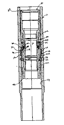
Referring initially to FIG. 1, there is illu~llated, in a ~lcÇcllcd embodiment
thereof, a cross-sectional view of a up-to-set lock mandrel 10 of the present invention
within a portion of a well conduit 12. The well conduit 12 may include casing, tubing,
well heads, trees, risers, liners; or downhole accessories, including landing nipples,
packers, valves, sleeves, mandrels, hangers, and seal bore extensions; or any colllbinaLion
of these devices used with respect to a well. As such, it should be understood that any
given well may have multiple conduits therein. For inct~nre, as is well known in the art,
a well may include casing, production tubing, and a packer, with the packer made up
within the tubing string, and the tubing string being positioned within and collcellllic to the
casing. The up-to-set lock mandrel 10 is set by application of an uphole force. The
application of an uphole force to set the up-to-set lock mandrel 10 is particularly
advantageous when the up-to-set lock mandrel 10 is coupled to a flow control device, such
as a safety valve, a plug, an injection valve, a choke, a plcs~urc-lellll)claLule recording
CA 02206170 1997-0~-26
device, a testing tool or a st~n-ling valve, just to name a few. The reason that the up-to-set
lock mandrel 10 is advantageous is that: since an up-to-set lock mandrel is set by the
application of an uphole force, a counter downhole force is typically required to unlock the
up-to-set lock mandrel. As such, the requirement of the downhole force prevents the up-
to-set lock mandrel 10 from being inadvellellLly removed from the well conduit 12 by the
uphole directional force created by the fluid flow within the well conduit 12. However, it
will be appreciated that the up-to-set lock mandrel 10 may have a number of applications
and can be used with a variety of downhole tools, including those mentioned above.
The portion of well conduit 12 has a locating profile 14 recessed or indented in an
interior sidewall 16 of the well conduit 12. The locating profile 14 may be positioned
allywhele along the length of the well conduit 12 where a no-go is desired, and there may
be a plurality of such profiles. As used herein, a no-go is a point below which a tool with
a pred~lelll~ ed .li~ tl r cannot be moved. As illustrated, the interior sidewall 16 is next
to the passageway 17 of the well conduit 12. Since the locating profile 14 is recessed or
indented in the interior sidewall 16, it does not protrude into the interior passageway 17 of
the well conduit 12, and thus, does not restrict the interior diameter passageway 17, as
does a convention no-go shoulder. In conventional settings, no-go shoulders are shoulders
that extend into the interior passageway of the well conduit to provide a stop point for a
tool. To pass any tool below the no-go shoulder, it must, th~refole, have an outer
."l~tel that is less than the rli~m~ter of the well conduit passageway as restricted by the
no-go shoulder. Because the up-to-set lock mandrel 10 cooperatively engages the recessed
locating profile 14 to function as a no-go for the up-to-set lock mandrel 10, a conventional
no-go, which restricts the ~i~mloter of well conduit's passageway 17, is not nlqcess~ry.
CA 02206170 1997-0~-26
The present invention, therefore, provides a distinct advantage over the prior art because
the present invention can be operated in a well conduit 12 that does not have a
conventional no-go shoulder anywhere along its length.
The locating profile 14 may be any type of recessed profile, however, in prer~lled
cases, the locating profile 14 is an ~X~9" or ~R~" type of profile. The locating profile 14
may include a square shoulder 18 or the profile may have varying degrees of slope.
Preferably, the varying degrees of slope may range from about 45~ to about 120~ from the
longit~ldin~ is of the well flow conduit 12, and the slope is such that it effectively
functions as a no-go when the up-to-set lock mandrel 10 engages the locating profile 14.
It should be noted that the profiles designated as X0 and R~ are well known and
understood by those skilled in the art. As previously mentioned, the well conduit 12 may
be various tools. However, the well conduit 12 is preferably a nipple either within a
production tubing string or within the well casing. Fur~ermore, the well conduit 12 is
preferably free of a no-go shoulder proximate the locating profile 14, thereby providing a
well conduit 12 that does not have a restricted passageway 17 proximate the locating
profile 14. As such, the present invention is ideally suited to be used in a well conduit 12
that does not have a conventional no-go shoulder anywhere along its length.
Co,~li.,.li,~ to refer to FIG. 1, the up-to-set lock mandrel 10 preferably comprises a
generally cylindrical body 20 and a locating key 22 coupled to the body 20. A locating
key 22 is biased to be urged from a seeking position toward a no-go position.
Preferably, the locating key 22 is held in position with respect to the body 20 by a key
retainer 22a and is coupled to the body 20 to allow radial translation relative thereto as the
locating key moves between the seeking position and the no-go position. Radial
CA 02206170 1997-0~-26
14
translation means that the locating key 22 moves in a radial direction with respect to the
body 20. As illustrated, the locating key 22 is in a seeking position, which is its normal
OpCIa~ g position as it is passed downhole through the well conduit 12. As such, the
locating key 22 is in constant contact with the sidewall 16 as it is being lowered through
the well conduit 12. This allows the locating key 22 to autom~tir~lly engage the matching
locating profile 14 when the locating key 22 encounters the locating profile 14. This can
be advantageous because the locating key 22 cannot be prematurely or inadvertently
deployed. The locating key 22 may be biased in any manner known to those skilled in the
art, however, it is preferably biased by a spring 24 that is coupled to the locking mandrel
10 by a screw 24a. In a plcfell~d embodiment, there are at least two locating keys 22 that
are positioned radially around the body 20. The locating key 22 has a no-go profile 26
thereon contoured to engage the locating profile 14 when the locating key 22 is in the no-
go position. Preferably, the no-go profile 26 includes a square shoulder 26a that is
contoured to engage the square shoulder 18 of the locating profile 14. However, the no-
go profile 26 may also have the same v~hlg degrees of slope that cooperatively
correspond to the slope of the locating profile 14 as previously mentioned above.
Whatever, the degree of slope, however, the no-go profile 26 engages the locating key 22
to thus uniquely function as a no-go for the up-to-set lock mandrel 10; that is, the no-go
profile 26 p,~ "l~ the up-to-set lock mandrel 10 from moving any further downhole when
the no-go profile 26 engages the locating profile 14. This unique aspect offers the distinct
advantage of providing a lock mandrel that does not need to be set in a conventional
landing nipple having a no-go shoulder that restricts the interior ~ meter or the
passageway 17 of the well conduit 12.
CA 02206170 1997-0~-26
In a more pler~llcd embodiment, the up-to-set lock mandrel 10 further includes a
locking mPchA~ 28, located proximate the locating key 22. The locking mechanism 28
is displaceable with respect to the body 20 between (1) a running position, wl~ eill the
locating key 22 is mAint~in~d in the seeking position, and (2) a set position, wherein the
locking mPçh~ni.cm 28 mAint~in~ the locating key 22 in the set position. The locking
m.oçhAni~m 28 may be displaced by a sliding action, a rotating action, or an expanding
action, such as that used in a collapsible sleeve. The locking mechAni~m 28 may be any
type of locking m~çh~ni~m known to those skilled in the art such as a locking sleeve or
expander sleeve, including a piston ~rt~lAted collapsible sleeve. In a preferred
embo-lim~nt however, the locking mechanism 28 is a locking sleeve and is located
radially inward of the locating key 22.
In those embo~ P~ where the locking m~chAni~m 28 is a locking sleeve, the up-
to-set lock mandrel 10 may further comprise a running tool profile 30 formed on an inner
surface of the locking mechanislll next to the passageway 17. The running tool profile 30
allows a running tool to engage the locking mechanism 28 to move it between the running
position and the set position. In such embodiments, the locking mech~ni~m 28 preferably
includes a shifting profile 32 that has a beveled lul~ g portion 34 and a beveled setting
portion 36 that extend OuLwaldly past the running portion 34 and toward the locating key
22. The shifting profile 32 and the locating key 22 are separated by a locating key pocket
38 in which the locating key 22 may be at least partially retracted so that the locating key
22 can traverse irregularities on the interior sidewall 16 in the well conduit 12. Thus, the
locating key 22 is coupled to the body 20 to allow radial translation of the locating key 22
CA 02206170 1997-0~-26
16
relative to the body 20 as the locating key 22 llal~vel~es the interior sidewall 16 of the
well conduit 12.
In a plcrcllcd embodiment, a lock reldillcl ring 40, which is preferably a snap ring
or "C" ring, co~ alively works with the locking mechanism 28 to m~int~in the locating
key 22 in the set position. Preferably, the locking mechanism 28 includes a detent or
annular boss 42 formed on the outer surface of the locking m.oçh~ni~m 28, wherein the
annular boss 42 has an increased outer (1i~m~ter. While the annular boss 42 is illustrated,
it will be appreciated that altern~tive embodiments may include a recessed portion 43 (See
FIG. 2) having a decreased outer tli~m~ter, as opposed to the raised annular boss 42. In
such embo limPnt~, the locking retainer ring 40 may contact or collapse into the recessed
portion 43 as the locking mPrh~ni~m 28 is moved from the seeking position to the set
position. Once the locking m~ch~ni~m 28 is in the set position, it m~int~in~ the locating
key 22 in the set position.
Rer~llillg now to the more plcfellcd embodiment, since the annular boss 42
extends oulwdldly, a certain amount of force is required to traverse the annular boss 42
across the lock lc~hlcl ring 40. When the locking mech~ni~m 28 is in the seeking
position, the lock retainer ring 40 is positioned uphole from the annular boss 42, as
illustrated in FIG. 1. Conversely, when the locking mechanism 28 is in the set position,
the lock rcldill~,r ring 40 is positioned downhole from the annular boss 42, as illustrated in
FIG. 3. The cooperation of the lock reldincl ring 40 and the annular boss 42 provide a
preÇellcd m.ocll~ni~m through which the locking mech~ni~m 28 m~int~in~ the locating key
22 in the set position. Of course, it will be apprcciated by those skilled in the art that
other locking mech~ni~ may be used as well to accomplishthe same result.
CA 02206170 1997-0~-26
The locking mech~ni~m 28 may also have vibration dampers 44, such as "o" rings,
positioned on its opposite ends. In certain applications, it is desirable to couple a
conventional flow control device 46 to the up-to-set lock mandrel 10. The flow control
device 46 may be one of the types listed above that are well known in the art. One such
device is a safety valve that is described in detail in the references that are incorporated
herein by rer.,l~llce. The,efole, only a partial schem~tic of the flow control device 46 is
shown.
Turning now to FIG. 2, the lock mandrel of FIG. 1 is shown with the locating key
22 engaged with the locating profile 14 of the well conduit and in the no-go position.
However, the locating key 22 is not yet set in the set position as illustrated by the fact that
the recessed portion 43 is positioned downhole from the lock retainer ring 40. Even
though the locating key 22 is not set, the no-go profile 26 of the locating key 22 is firmly
engaged with the locating profile 14 of the well conduit 12. With the no-go profile 26 so
engaged, the up-to-set lock mandrel 10 cannot be moved downhole any further.
Referring now to FIG. 3, the up-to-set lock mandrel 10 of FIG. 1 is shown with
the locking mloe1l~ni~m 28 moved uphole and held in place by the lock retainer ring 40 to
thereby m~int~in the locating keys 22 in the set position. In this figure, sufficient uphole
force was exerted on the locking mPr~ n 28 to traverse the detent or annular boss 42
across the lock re~iller ring 40, thereby c~luling the re~illel ring 40 belweell the annular
boss 42 and the beveled 1 ul~lPillg profile 34. Additionally, the beveled setting profile 36 is
f~nly engaged against the locating key 22. The Cd~tulillg of the lock ~ ler ring 40
causes the locking mPch~ni~m 28 to m~int~in the locating key 22 in the set position.
When the locking mrrll~ni~m 28 is in the set position, the up-to-set lock mandrel 10
CA 02206170 1997-0~-26
18
cannot be moved either uphole or downhole because the lock mechanism 28 prevents the
locating key 22 from diseng~gin~ from the locating profile 14.
Turning now briefly to FIG. 4, there is illustrated the lock mandrel of FIG. 1 with
the locking mech~ ,., 28 moved back downhole to thereby allow the locating keys 22 to
move inwardly and disengage from the set position. In this figure, sufficient downhole
force was exerted on the locking mPch~ni~m 28 to traverse the annular boss 42 back across
the lock retainer ring 40, thereby releasing the retainer ring 40 from its previous captured
position as shown in FIG. 3. As illustrated in FIG. 4, annular boss 42 is again downhole
from the lock retainer ring 40. Additionally, the beveled setting profile 36 has been
shifted downhole and is no longer engaged against the locating key 22, thereby allowing
the locating key 22 to move inwardly and release from the no-go position. The no-go
profile 26 is contoured such that the beveled faces that comprise the no-go profile 26 allow
the up-to-set lock mandrel 10 to disengage from the locating profile 14 and be moved
uphole only but the no-go profile prevents the up-to-set lock mandrel 10 from being
moved downhole any further.
Turning now to FIG. 5, there is illustrated a plurality of locating key 22 having a
plurality of shoulders 26a and 26b associated the.e~ . The well conduit 12 may have a
plurality of locating profiles 14 and 54 recessed in its sidewall 16. In such in~t~nre, the
locating key 22 can be configured to have a no-go profile 26 that is collloul ed to engage a
selective one of the plurality of the locating profiles 14 and 54. Thus, the no-go profile 26
can be colllouled for engagement with a specific locating profile 14, thereby allowing the
no-go profile 26 to bypass the other locating profile 54 that is located above that specific
locating profile 14 within the well conduit 12.
CA 02206170 1997-05-26
19
With the invention having been described, a plcÇellcd method of its operation with
reference to FIGs. 1-4 will now be ~ cl1ssed Prior to the insertion of the up-to-set lock
mandrel 10 in the well conduit 12, a conventional flow control device 46 can be coupled to
the downhole end of up-to-set lock mandrel 10 if so desired. As the up-to-set lock
mandrel 10 is positioned in the well conduit 12, the locating keys 22 are urged outwardly
to a seeking position against the sidewall 16 as the up-to-set lock mandrel 10 is moved
downhole. If the locating keys 22 encounter an irregularity in the sidewall 16 of the well
conduit 12, the locating keys 22 can retract radially into the locating key pocket 38 slightly
to allow them to bypass the irregularity. When the locating keys 22 reach the locating
profile 14 that is recessed in the sidewall 16, the locating key 22 is urged into the locating
profile 14, and the no-go profile 26 engages the locating profile 14, which stops the
downhole movement of the up-to-set lock mandrel 10.
A conventional l~ ~ing tool is then used to engage the running tool profile 30 on
the interior sidewall of the locking mechAni~m 28, and an uphole force is exerted against
the locking mech~ni.cm 28 via the running tool. An uphole force sufficient to slide the
annular boss 42 across the lock retainer ring 40 is exerted such that the lock retainer ring
40 is positioned between the annular boss 42 and the beveled running profile 34 of the
locking mPchA~ 28. As the locking mPrh~ni.~m 28 is moved uphole, the beveled
setting profile 36 engages the locating key 22 and mAint~in~ the locating key 22 in the set
position. The locking mechAni~ 28 is held in this set position by the lock retainer ring
40, which is captured between the annular boss 42 and the beveled running profile 34.
When so positioned, the lock retainer ring prevents the locking m~chAni~m 28 from
shifting downhole to the running position. Once operations are complete or if the up-to-
CA 02206170 1997-0~-26
set lock mandrel 10 needs to be removed from the well conduit 12 a conventional pulling
tool is used to exert a downhole force on the locking mechanism 28 sufficient to cause the
annular boss 42 to traverse the lock ~c~hler ring 40 and thereby position the annular boss
42 downhole from the lock retainer ring 40. As a result of this shifting action the beveled
setting profile 36 is shifted downhole from the locating key 22 which allows the locating
key 22 to be urged inward into the locating key pocket 38 when the lock mandrel is lifted
out of the nipple. The conventional pulling tool lifts the lock mandrel by en~ging the fish
neck 55 of the lock mandrel. The no-go profile 26 is then allowed to disengage from the
locating profile 14. The up-to-set lock mandrel 10 can then be removed from the well
conduit 12.
From the above ~i~cll~sion it is a~alc"l that the present invention provides a lock
mal1d~1 for lcgi~te~ with the locating profile in a well conduit. The well conduit is
preferably either a nipple within the production tubing or a nipple within the well casing.
The well conduit is free of a no-go shoulder proximate the locating profile. Thus the well
conduit does not have a lc~lliclcd inside ~i~m~ter proximate the locating profile. The no-
go profile preferably includes a square shoulder co"~ou,cd to engage a corresponding
square shoulder of the locating profile. In a ple~lled embodiment the lock mandrel is an
up-to-set lock mandrel that col,~lises a generally cylindrical body and a locating key
coupled to the body and biased to be urged from a seeking position toward a no-go
position. The locating key has a no-go profile thereon contoured to engage the locating
profile when the locating key is in the no-go position to thereby function as a no-go for
the up-to-set lock mandrel. Preferably, the locating key is coupled to the body to allow
radial translation of the locating key relative to the body as the locating key (1) contacts
CA 02206170 1997-0~-26
the interior side wall of the well conduit as the lock mandrel is run in the well and (2)
moves belweell the seeking position and the no-go position. The lock mandrel further
includes a locking m~ch~ni.~m located adjacent the locating key and displaceable with
respect to the body between a ~ g position wherein the locating key is m~int~in-o(l in
the seeking position and a set position, whelein the locking sleeve sustains the locating key
in the set position.
Although the present invention and its advantages have been described in detail,
those skilled in the art should understand that they can make various changes, substitutions
and alterations herein without depa.ling from the spirit and scope of the invention in its
broadest form.
WHAT IS CLAIMED IS: