Note: Descriptions are shown in the official language in which they were submitted.
-
CA 02206~12 1997-0~-29
1.
MUSICAL INSTRUMENT SUPPORT
BACKGROUND OF THE INVENTION
1. FIELD OF THE INVENTION
The present invention relates to a chair-borne
musical instrument support More specifically, the
invention is a portable and adjustable stand for
supporting tubas or other musical instruments while
seated in a chair.
2. DESCRIPTION OF PRIOR ART
A concert style tuba is designed to be played with
the lower end of the tuba resting on the musician's
thighs, while the upper end is balanced upright by the
musician's arms and hands. Many musicians are able to
successfully balance the instrument in the proper
manner upon their lap, but this can be tiring task
since it is generally a constant struggle. The
instrument has the tendency to slide down the
musician's thigh as the instrument is being played
and, therefore, it may need nearly continuous
readjustment. The instrument can also be fairly heavy
and, therefore, create uncomfortable pressure on the
musician's thighs.
While many musicians are able to play the instrument
in the recommended manner, holding this rather large
and awkward instrument can be almost impossible for
some musicians, and it can be tedious and difficult
for others. Beginning players, young children, and
senior citizens may have a tremendous amount of
difficulty stabilizing the instrument upon their lap
during playing. Individuals with certain handicaps
may find that the task of supporting the instrument
CA 02206~12 1997-0~-29
upon their lap tedious and tiring, or even
impossible.
In an effort to make playing the tuba more
comfortable, many musicians will slide back in their
chairs and rest the tuba on the front corner of their
seat between their legs. This is especially true when
the musician spends a long time playing the
instrument. While this makeshift solution does
relieve the pressure on the musician's lap, it results
in an awkward sitting position for the musician.
A chair-borne device is needed which is capable of
acting as a musical instrument support for a tuba or
other musical instrument. The musical instrument
support should be portable and adjustable. The
musical instrument support should provide the musician
with the sense that the instrument is being balanced
on a musician's lap, yet at the same time allow the
musician to be more comfortable and to more easily
manage the instrument. The musical instrument support
should not compromise the acoustic characteristics of
the instrument, nor should it scratch the instrument.
The musical instrument~support should accommodate use
by a range of musicians of varying body size, as well
as accommodate a variety of different musical
instruments.
The following patents describe musical instrument
supports which are either integrated into the design
of a chair or are bulky, thereby rendering these
devices difficult to transport. U.S. Patent Number
2,575,540, issued on November 20, 1951, to Harry J.
Wenger describes a combined seat and support for large
musical instruments such as a sousaphone. U.S. Patent
Number 3,193,325, issued on July 6, 1965, also to
Harry J. Wenger describes an adjustable combination
seat and support for large musical instruments such as
a sousaphone. U.S. Patent Number 3,259,428, issued on
July 5, 1966, to Harry J. Wenger et al., describes an
CA 02206~12 1997-0~-29
adjustable combination seat and support for a tuba.
U.S. Patent Number 4,065,994, issued on January 31
1978, and U.S. Patent Number 4,067,527, issued on
January 10, 1978, both issued to James L. Streit
describe an adjustable free standing structure for
supporting a musical instrument.
U.S. Patent Number 3,024,690, issued on March 13,
1962, to John L. Sanstead describes a sousaphone
support including a leg having an adjustable length,
the lower end of which is adapted to be supported in
a number of selected positions, and the upper end of
which is adapted to be secured to the instrument. The
patent to Sanstead describes an instrument support
which when used while seated requires that the
musician not only balance the instrument on the
support, but also balance the support itself.
U.S. Patent Number 3,811,357, issued on May 21,
1974, to Merlin D. Stewart describes a tuba supporting
rod that is attached to the tuba and serves as an
adjustable stand, supporting the tuba from the surface
of the seat. The patent to Stewart describes a
musical instrument support which is fixedly attached
to the instrument, thereby requiring modification of
the instrument. The patent to Stewart does not
describe a device which may be used with any suitable
musical instrument without modification of the
instrument.
U.S. Patent Number 4,441,683, issued on April 10,
1984, to Richard G. Mayne describes a storage holder
for cumbersome instruments, such as tubas, that
provides support in either a horizontal or a vertical
orientation. The patent to Mayne describes a device
for use as a means for storing the instrument and
fails to describe an adjustable device for supporting
a musical instrument while the instrument is being
played.
CA 02206~12 1997-0~-29
None of the above inventions and patents, taken
either singularly or in combination, is seen to
describe the instant invention as claimed. Thus a
musical instrument support solving the aforementioned
problems is desired.
SUMMARY OF THE INVENTION
The present invention is a chair-borne musical
instrument support that is both adjustable and
portable. The musical instrument support includes a
seat portion from which a height-adjustabe support arm
depends, the upper end of the support arm terminating
with an instrument rest. The seat portion rests on
the seat of a chair; the musician then sits on the
seat portion, to act in part as a counterweight to the
weight of the instrument to be placed on the
instrument rest, and, holding the device itself firmly
in place from the weight of the musician.
Alternatively, the musical instrument support may be
held in place on a chair by adjustable straps.
The support arm and instrument rest is positioned to
extend upward between the legs of the musician from
the seat portion proximate to the front edge of the
chair. The base of a large musical instrument, e.g.
a tuba, is then placed upon the instrument rest,
covered with a non-skid, non-abrasive surface
material. The support arm and instrument rest is
vertically adjustable to allow the musician to choose
a comfortable height for playing the instrument.
The instrument thus is allowed to rest in the same
position as if it were being held on the musician's
lap without being borne by the musician's legs. The
musical instrument support is not permanently attached
to the chair, therefore the support may be easily
removed and carried with the musician or stored for
later use. Several embodiments of the present
CA 02206~12 1997-0~-29
invention are contemplated which are designed to be
used by different size musicians and with different
types of instruments.
Accordingly, it is a principal object of the
invention to provide a chair-borne device for
supporting a large musical instrument.
It is another object of the invention to provide a
musical instrument support that is portable and is
capable of being used with any conventional chair.
It is a further object of the invention to provide
a musical instrument support that is adjustable to
accommodate different size musicians and different
size instruments.
Still another object of the invention is to provide
a musical instrument support which when in use by a
musician simulates the feel of balancing an instrument
on the musician's lap, yet allows the musician to be
comfortable and to easily manage the instrument. Itis
another object of the invention to provide a musical
instrument support which does not compromise the
acoustic characteristics of the instrument.
It is a further object of the invention to provide
a musical instrument support constructed or surfaced
so as to minimize the risk of scratching the surface
of the instrument which is being supported.
Still another object of the invention is to provide
a musical instrument support having means for
supporting varying sizes and shapes of instruments.
It is an object of the invention to provide improved
elements and arrangements thereof in a musical
instrument support for the purposes described which is
inexpensive, dependable and fully effective in
accomplishing its intended purposes.
These and other objects of the present invention
will become readily apparent upon further review of
the following specification and drawings.
CA 02206~12 1997-0~-29
BRIEF DESCRIPTION OF THE DRAWINGS
Figure 1 is an environmental, perspective view of a
musical instrument support according to the first
embodiment of the present invention.
Figure 2 is an environmental, perspective view of a
musical instrument support according to the second
embodiment of the present invention including an
adjustable strap and hook.
Figure 3 is an environmental, perspective view of a
musical instrument support according to the third
embodiment of the present invention including a pair
of adjustable straps.
Figure 4 is an environmental, perspective view of a
musical instrument support according to the fourth
embodiment of the present invention.
Similar reference characters denote corresponding
features consistently throughout the attached
drawings.
DETAILED DESCRIPTION OF THE PREFERRED EMBODIMENTS
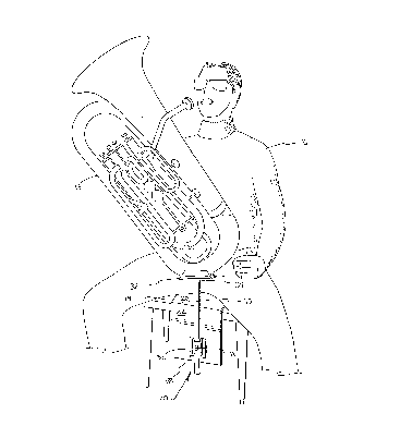
Referring to Figure 1, the present invention is a
chair-borne musical instrument support 10 that is both
adjustable and portable. The musical instrument
support 10 includes a seat portion 20, a height-
adjustable support arm 30 attached to the seat portion
20, and an instrument rest 32 terminating the top end
of the support arm 30. The musician 16 has placed the
seat portion 20 of the device 10 on the seat 14 of a
chair, and has seated himself on the seat portion 20.
The instrument 18 has then been placed on the
instrument rest 32, rather than on the musician's lap.
Figures 1 through 4 show a variety of representative
embodiments of the present invention, but in no way
serves to exhaust all of the embodiments contemplated
by the present invention.
CA 02206~12 1997-0~-29
The first embodiment of the present invention is
shown in Figure 1. The first embodiment of the
present invention is especially well adapted for
children or small adults, since the support arm 30 and
- the instrument rest 32 may be adjusted to below the
chair seat 14 level. This embodiment allows the
musician 16 to adjust the level of the instrument 18
upon the instrument rest 32 so that the musician 16
can comfortably play the instrument 18.
The first embodiment includes a seat portion 20
having a downwardly extending portion 22. A mounting
plate 36 is attached to the downwardly extending
portion 22, and a sleeve 38 is rigidly affixed to the
mounting plate 36. The support arm 30 fits through
the sleeve 38 and is held in a fixed position within
the sleeve by a locking mechanism. The locking
mechanism shown in Figure 1 is a knob 40 which has a
threaded screw (not shown) extending therefrom. The
threaded screw mates with a threaded hole (not shown)
on the sleeve 38, such that when the knob 40 is
rotated in the proper direction the screw moves
through the hole in the sleeve 38 and contacts the
support arm 30. The frictional forces between the
screw and the support arm 30 prevent the support arm
30 from sliding through the sleeve 38.
A wide variety of commonly known locking mechanisms
may alternatively be used with the present invention.
For example, the knob 40 may have a rod (not shown)
extending therefrom which extends through a hole (not
shown) in the sleeve 38. The knob 40 may be spring
biased to push the rod through the hole in the sleeve
38 and into one of a series of holes (not shown)
aligned in a row along the length of the support arm
30. The height of the support arm is adjusted by
pulling the knob 40 away from the sleeve 38 so that
the rod attached to the knob 40 becomes disengaged
with the hole on the support arm 30, and sliding the
.
CA 02206~12 1997-0~-29
support arm 30 to the desired position and releasing
the knob 40, thereby re-engaging the rod and one of
the holes. One benefit of using the frictional
locking mechanism discussed in the previous paragraph
as compared to the spring-biased knob, is that the
frictional locking mechanism allows for angular
adjustment of the instrument rest 32 about the axis of
the support arm 30 if the musician 16 so desires.
As is true with all four of the embodiments of the
present invention discussed herein, the seat portion
20 of the first embodiment is made of a thin rigid
material which is preferably lightweight for easy
transportability. Certain types of conventionally
known plastics would serve this purpose well, as would
other similar materials. The support arm 30 and
instrument rest 32 are also made of a rigid yet
lightweight material, such as conventionally known
types of plastics or other similar materials. All
four embodiments of the present invention may also
provide a cushion (not shown) covering the upper
surface of the seat portion 20. The cushion would
make sitting on the seat portion 20 more comfortable
for the musician 16. All four embodiments may also
include a non-skid pad or cushion 34 on -the upper
surface of the instrument rest 32. The pad 34 would
not only protect the instrument 18 from scratching or
denting by the instrument rest 32, but it would also
prevent the base of the instrument 18 from sliding off
of the instrument rest 32. The pad 34 can be made of
rubber or some other similar material.
The musician 16 uses the instrument support 10 by
placing the device 10 in position on the seat 14 of
the chair, as shown in Figure 1, and sitting on the
seat portion 20 of the instrument support 10. The
support arm 30 and instrument rest 32 extend upward
near the front edge of the seat 14 and between the
legs of the musician 16. The weight of the musician
CA 02206~12 1997-0~-29
.
16 sitting on the seat 14 holds the instrument support
10 in place. The support arm 30 and instrument rest
32 may then be adjusted vertically up or down to a
comfortable height. The base of the instrument 18 is
then-placed upon the instrument rest 32. The
instrument 18 then rests in the same position as if it
were being held on the musician's lap without having
to be borne by the musician's legs.
The second embodiment of the present invention is
shown in Figure 2. The second embodiment of the
present invention is also especially well adapted for
children or small adults, since the support arm 30 and
the instrument rest 32 may be adjusted to below the
chair seat 14 level. The second embodiment is also
shown with one embodiment of an adjustable fastening
mechanism which is used to help hold the instrument
support 10 on the seat 14 of the chair.
The second embodiment includes a seat portion 20
with both a downwardly extending portion 22 and an
outwardly extending portion 24. A mounting plate 42
is rigidly fixed to the outwardly extending portion
24. A threaded hole 43 extends through the mounting
plate 42. In the second embodiment the support arm 30
is externally threaded such that the threads on the
support arm 30 mate with the threads inside the hole
43. The support arm 30 is then rotated to adjust the
height of the instrument rest 32. The instrument rest
32 can be rotatably mounted to the support arm 30 to
eliminate the need for rotating the instrument rest
32, and an instrument sitting therein, in order to
adjust the height of the instrument rest 32.
Alternatively, several other conventional height
adjustment mechanisms can be used with the threaded
support arm 30 to achieve similar results to those
discussed above. For example, the mounting plate
could be replaced by a collar (not shown), which could
be rotatably mounted on the outwardly extending
CA 02206~12 1997-0~-29
portion 24. In this configuration, the height of the
instrument rest 32 will be adjusted when the collar is
rotated by the musician and the lnstrument rest 32 is
prevented from rotating.
The second embodiment is shown with one embodiment
of an adjustable fastening mechanism which is used to
help hold the instrument support 10 on the seat 14 of
the chair. This embodiment of the fastening mechanism
includes a strap 50, a rigid hook 54, and mating hook
and loop fasteners 56 on the strap 50. The strap 50
is attached to the seat portion 20 at 52. The strap
50 extends through a slot on the hook 54 and can be
overlapped back onto itself such that the hook and
loop fasteners mate. Other conventional adjustment
mechanisms may be used to achieve similar results.
The hook 54 grasps the rear edge of the seat 14 and
thereby prevents the instrument support 10 from
sliding off the front edge of the seat 14. This
embodiment of the fastening mechanism may be used with
any of the four embodiments of the instrument support.
The third embodiment of the present invention is
shown in Figure 3. The third embodiment of the
present invention is well adapted for adults or for
smaller instruments, since the support arm 30 and the
instrument rest 32 may not be adjusted to below the
chair seat 14 level. The third embodiment is also
shown with a different embodiment of an adjustable
fastening mechanism which is used to help hold the
instrument support 10 on the seat 14 of the chair.
The third embodiment includes a seat portion 20 that
extends outward beyond the front edge of the seat 14.
The height adjustment mechanism of the third
embodiment is identical to that of the second
embodiment, except that the mounting plate 42 is fixed
to the seat portion 20.
The third embodiment is shown with a different
embodiment of an adjustable fastening mechanism which
CA 02206~12 1997-0~-29
- 11
is used to help hold the instrument support 10 on the
seat 14 of the chair. This embodiment of the
fastening mechanism includes a pair of straps, 60 and
62, and mating hook and loop fasteners, 64 and 66, on
the straps, 60 and 62 respectively. The straps, 60
and 62, are attached to the seat portion 20 at 61 and
63, respectively. The straps, 60 and 62, extend
around the supports for the back 12 of the chair and
overlap back onto themselves such that the hook and
loop fasteners mate. Other conventional adjustment
mechanisms may be used to achieve similar results.
The straps, 60 and 62, grasp the supports for the back
12 of the chair and thereby prevent the instrument
support 10 from sliding off the front edge of the seat
14. This embodiment of the fastening mechanism may be
used with any of the four embodiments of the
instrument support.
The fourth embodiment of the present invention is
shown in Figure 4. The fourth embodiment of the
present invention is well adapted for adults or for
smaller instruments, since the support arm 30 and the
instrument rest 32 may not be adjusted to below the
chair seat 14 level.
The fourth embodiment includes a seat portion 20
that extends outward beyond the front edge of the seat
14 which is identical to that of the third embodiment.
The height adjustment mechanism of the fourth
embodiment is identical to that of the third
embodiment, except that the support arm 30 has a bent
portion 44. The bent portion 44 may be oriented to
eccentrically position a musical instrument such that
the instrument rest 32 is closer to the rear of the
seat 14, as shown in Figure 4, or so that the
instrument rest 32 is farther away from the rear of
the seat 14. The bent portion 44 allows certain
musicians to find a more comfortable playing position
CA 02206~12 1997-0~-29
12
then they might otherwise find with the first, second
and third embodiments.
It should be noted that in all four of the
embodiments of the present invention, the musical
instrument support 10 is not permanently attached to
the chair, therefore the support 10 may be easily
removed and carried with the musician or stored for
later use.
It is to be understood that the present invention is
not limited to the embodiments described above, but
encompasses any and all embodiments within the scope
of the following claims.