Language selection

Search

Patent 2207139 Summary

Third-party information liability

Some of the information on this Web page has been provided by external sources. The Government of Canada is not responsible for the accuracy, reliability or currency of the information supplied by external sources. Users wishing to rely upon this information should consult directly with the source of the information. Content provided by external sources is not subject to official languages, privacy and accessibility requirements.

Claims and Abstract availability

Any discrepancies in the text and image of the Claims and Abstract are due to differing posting times. Text of the Claims and Abstract are posted:

  • At the time the application is open to public inspection;
  • At the time of issue of the patent (grant).
(12) Patent Application: (11) CA 2207139
(54) English Title: IMPROVED STRUCTURE FOR MINIATURE LAMP
(54) French Title: STRUCTURE AMELIOREE POUR LAMPE MINIATURE
Status: Deemed Abandoned and Beyond the Period of Reinstatement - Pending Response to Notice of Disregarded Communication
Bibliographic Data
(51) International Patent Classification (IPC):
  • H01K 01/18 (2006.01)
  • F21V 19/00 (2006.01)
  • H01R 33/09 (2006.01)
(72) Inventors :
  • HUANG, PETER K. H. (Taiwan, Province of China)
(73) Owners :
  • SHINING BLICK ENTERPRISES CO., LTD.
(71) Applicants :
  • SHINING BLICK ENTERPRISES CO., LTD. (Taiwan, Province of China)
(74) Agent: MARKS & CLERK
(74) Associate agent:
(45) Issued:
(22) Filed Date: 1997-06-05
(41) Open to Public Inspection: 1998-12-05
Availability of licence: N/A
Dedicated to the Public: N/A
(25) Language of filing: English

Patent Cooperation Treaty (PCT): No

(30) Application Priority Data: None

Abstracts

English Abstract


An improved miniature lamp structure, wherein, two
conductors are positioned by a burned bead in the lamp
bulb, a tungsten filament is provided on the top of the
conductors of which the ends extend outwardly of a flat
insertion connecting end of the lamp bulb; it is
characterized in that, the outwardly extending ends of the
conductors are bended to be positioned on the two
lateral sides of the flat insertion connecting end, so that
they can be connected directly with two power line metal
sheets provided in a connecting base. Metal contact
sheets or caps required by ordinary miniature lamps can
be saved in the present invention.


French Abstract

La présente invention vise une lampe miniature améliorée, Dans le cas de cette invention, la position de deux conducteurs est déterminée par une bille brûlée dans l'ampoule de la lampe et un filament de tungstène est monté au-dessus des conducteurs dont les extrémités font saillie hors de l'élément de connexion plat de l'ampoule de la lampe. L'invention se différencie en ce que les extrémités en saillie des conducteurs sont repliées pour être insérées des deux côtés de l'élément de connexion plat de telle sorte qu'elles puissent être connectées directement à deux plaquettes de métal sous tension montées dans une base de connexion. La présente invention peut ainsi être réalisée sans les plaques ou les couvercles de contact en métal habituellement nécessaires à l'assemblage de lampes miniatures.

Claims

Note: Claims are shown in the official language in which they were submitted.

CLAIMS
1. An improved connecting structure for a miniature
lamp, it is comprised of in the glass lamp bulb thereof:
two conductors positioned by a burned bead, a tung
-sten filament of specific length being provided between
the top of said conductors, the lower ends of said
conductors extend outwardly of a flat insertion connecting
end of the lamp bulb;
the structure is characterized in that:
the outwardly extending ends of said conductors
are bended to be positioned on the two lateral sides of
said flat insertion connecting end, so that they can be
connected directly with two power line metal sheets
provided in a connecting base.
2. An improved connecting structure for a miniature
lamp as claimed in claim 1, wherein,
said flat insertion connecting end is provided
with two raised strips, and an engaging protrusion is
provided on each of said two raised strips, two engaging
lugs correspondingly provided to said two engaging
protrusion are located on the wall of a connecting hole in
said connecting base.
-8-

Description

Note: Descriptions are shown in the official language in which they were submitted.


CA 0220il39 1997-06-0~ -
TITLE: IMPROVED STRUCTURE FOR MINIATURE LAMP
The present invention is re~ated to an improved con-
necting structure for a miniature lamp, and especially to
which wherein the internal conductors are directly bended
and close to the two lateral surfaces of an insertion con
-necting end of a lamp bulb, so that a telescopically
slipping over connecting member or related metal sheet
conductors can be saved.
BACKGROUND OF THE INVENTION
1. Field of the Invention
Ordinary miniature lamp bulbs mostly are made of
glass, two conductors are provided in the vacuum interior
of each lamp bulb, a short tungsten filament is provided
between the upper ends of the conductors, the conductors
tg are extended with the other ends thereof through a glass
spherical body and then are connected to the electric su-
PPly.
2. Description of the Prior Art
Such lamp structures available nowadays include the
types stated below:
The first one is shown in Fig. 1, wherein, a conven-
tional ball shaped lamp bulb 10 is provided with a flat
insertion connecting end 11, two separately located con-
ductors 12, 13 are positioned by a burned bead 14, a tung
-sten filament 15 of predetermined length and for emit-
ting light is provided on the top of the conductors 12,
--1--

CA 02207139 1997-06-05
13. The lower ends of the conductors 12, 13 are bended to
render the bending sect~ons 16, 17 thereof to be close to
the front and the rear surfaces of the flat insertion con
-necting end 11 respectively. Such a lamp 10 ~enerslly
must be assembled onto a connecting base 20 which ordi-
narily is provided with an 1nternal hole 21 for tele-
scopically connecting with the flat insertion connecting
end 11, two metal sheets 22, 23 on a power line are pro-
vided on both sides respectively of the internal h~le 21,
four front and rear metal contact sheets 24, 2~ are pro-
vided for connecting with the bending sections 16, 17 o~
the conductors 12, 13. So that when the lamp 10 is assem-
bled onto the connectin~ base 20, the bending sections
16, 17 of the conductors 12, 13 are connected to the four
1~ internal metal contact sheets 24, 25 respectively, then
the metal contact sheets 24, 25 are connected to the elec
-tric wires, the lamp can thus be turned on to emit light
. While defect of such lamp is that it must use more me-
tal contact sheets 24, 25.
The second one is shown in Fig. 2, wherein, the con-
ventional structure of a Christmas lamp is shown, the
ends 33, 34 of two conductors 31, 32 ~rom a Christmas
lamp bulb 30 thereof are extended in straight lines out
of the glass body and are extended through two correspon-
2~ ding holes provided ~n th~ bottom of a plastic cap 3~,
then are bended to be close to the two lateral sides of
-2-

CA 02207139 1997-06-0~ '
the plastic cap 35 at the lower end thereof. The plastic
cap 35 with the lamp bulb 30 assembled thereon then is
connected to a connecting sleeve 36, the ends 33, 34 ex-
posed can contact the internal metal contact sheets 37,
38 provided in the connecting sleeve 36. While defect of
such lamp is that it must use an extra plastic cap 35.
The third one is shown in Fig. 3, wherein, an elonga-
ted lamp bulb 40 on a screw type lamp is shown, the lower
ends of two conductors 41, 42 from the lamp bulb 40 are
extended outwardly to be welded to an external screw cap
43, and then are screw coupled in an inner plastic screw
hole of a connecting base 45, and contact the internal
metal contact sheets 47, 48 provided in the plastic screw
hole. Such lamp also must use a meta~lic external screw
cap 43.
SUMMARY OF THE INVENTION
The object of the present invention is to provide an
improved connecting structure for a miniature lamp, where
-in, the lower ends of two conductors from the lamp bulb
are extended outwardly to be positioned on the two later-
al sides of a flat insertion connecting end thereof, so
that the lamp bulb can be assembled in the connecting ba-
se directly without providing extra metal contact sheets
or cap, production cost of such non-expensive miniature
lamps can be largely and effectively reduced.
The present invention will be apparent in its novelty
--3--

CA 02207139 1997-06-0~ '
and other characterist;cs after reading the detailed des-
cription of the preferred embodiments thereof in referen-
ce to the accompanying drawings.
BRIEF DESCRIPTION OF THE DRAWINGS
In the drawings:
Fig. 1 is an analytic perspective view of a conven-
tional ball shaped miniature lamp;
Fig. 2 is an analytic perspective view of a conven-
tional Christmas lamp;
Fig. 3 is an analytic perspective view of a conven-
tional elongated miniature lamp;
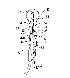
Fig. 4 is an analytic perspective view of an embodi-
ment of the present invention;
Fig. 5 is a partial sectional view of the embodiment
shown in Fig. 4;
Fig. 6 shows another embodiment of the present inven-
tion;
Fig. 7 shows a further embodiment of the present in-
vention.
DETAILED DESCRIPTION OF THE PREFERRED EMBODIMENT
Referring firstly to Fig. 4, taking Christmas lamps
as an example, the present invention is also provided
with two conductors 51, 52 in a Christmas lamp bulb 50
thereof, the conductors ~1, 52 are positioned by a burned
bead 53, a tungsten filament 54 is provided on the top of
the conductors 51, 52, the present invention is charac-
--4--

CA 02207139 1997-06-0~ '
terized mainly in that, the outwardly extending ends 55,
56 of the conductors 51, 52 are bended to be close to the
two lateral sides 58, 59 of a flat insertion connecting
end 57 of the lamp bulb 50, meanwhile, two raised strips
570 are provided respectively on the front and the rear
surfaces of the flat insertion connecting end 57, and an
appropriate engaging protrusion 571 is provided on each
of the two raised strips 570.
The above stated Christmas lamp bulb 50 can therefore
be assembled in the connecting hole 61 of a connecting
base 60, now the engaging protrusions 571 on the flat in-
sertion connecting end 57 can be snaP engaged with two
engaging lugs 64, 65 on the wall of the connecting hole
61; the outwardly extending ends 55, 56 of the conductors
51, 52 bended to be close to the two lateral sides 58, 59
of the flat insertion connecting end 57 are directly
press connected with two internal power line metal sheets
62, 63 provided in the connecting hole 61 (referring to
Fig. 5). Thereby, no intermediate (plastic) cap is re-
quired as is the case of the above stated conventional
structure.
In another embodiment such as is shown in Fig. 6, the
present invention is also provided with a flat insertion
connecting end 71 at the lower portion of the lamp bulb
70, the outwardly extending ends 74, 75 of two conductors
72, 73 provided therein are bended to be close to the two
-5-

CA 02207139 1997-06-0~ -
lateral sides of the flat insertion connecting end 71, so
that they can be connected directly with two power line
metal sheets 77, 78 provided in the connecting hole of a
connecting base 76. In order to increase the capability
of positioning of such insertion, the flat insertion
connecting end 71 mentioned above can also be provided
with two raised strips 79 and two engaging protrusions
791 rspectively on the front and the rear surfaces there-
of. It can be seen from this embodiment that, the embodi-
ment can save the four originally necessary internal me-
tal contact sheets in conventional arts such as is the
case of the first type of the ordinary miniature lamps.
In another embodiment of an elongated lamp such as
that shown in Fig. 7, the present invention is also pro-
vided with two conductors 81, 82 in the lamp bulb 80, the
outwardly extending ends of the conductors 81, 82 are
bended to be close to the two lateral sides of a flat in-
sertion connecting end 83 of the lamp bulb 80, the whole
lamp bulb 80 can therefore be assembled directly in the
connecting hole 8~ with a metallic surface of a connect-
ing base 84, and two raised strips 86 and two engaging
protrusions 861 provided thereon can be snap engaged with
two engaging lugs 87 on the wall of the connecting hole
of the connecting base 84, the protruding sections of the
conductors 81, 82 on the lateral sides are press contact-
ed with the internal power line metal sheets 88, 89 to
-6-

CA 02207139 1997-06-0~ '
thereby save a metal cap conventionally required at the
bottom of the miniature lamp bulb 80.
In view that the miniature lamp sets available in the
markets are almost mass produced, unit price thereof is
. very low, so th~at their competitiveness and yield of pro-
duction can both be increased, and because the present
invention can save internal metal contact sheets or caps,
it owns a great economic benefit in production, and thus
has high industrial value.
Having thus described my invention, what I claim as
new and desire to be secured by Letters Patent of the
~nited States is:

Representative Drawing
A single figure which represents the drawing illustrating the invention.
Administrative Status

2024-08-01:As part of the Next Generation Patents (NGP) transition, the Canadian Patents Database (CPD) now contains a more detailed Event History, which replicates the Event Log of our new back-office solution.

Please note that "Inactive:" events refers to events no longer in use in our new back-office solution.

For a clearer understanding of the status of the application/patent presented on this page, the site Disclaimer , as well as the definitions for Patent , Event History , Maintenance Fee  and Payment History  should be consulted.

Event History

Description Date
Inactive: IPC from MCD 2006-03-12
Time Limit for Reversal Expired 2000-06-05
Application Not Reinstated by Deadline 2000-06-05
Deemed Abandoned - Failure to Respond to Maintenance Fee Notice 1999-06-07
Application Published (Open to Public Inspection) 1998-12-05
Classification Modified 1997-09-04
Inactive: IPC assigned 1997-09-04
Inactive: First IPC assigned 1997-09-04
Letter Sent 1997-08-14
Inactive: Filing certificate - No RFE (English) 1997-08-14
Application Received - Regular National 1997-08-13
Inactive: Applicant deleted 1997-08-13

Abandonment History

Abandonment Date Reason Reinstatement Date
1999-06-07

Fee History

Fee Type Anniversary Year Due Date Paid Date
Registration of a document 1997-06-05
Application fee - small 1997-06-05
Owners on Record

Note: Records showing the ownership history in alphabetical order.

Current Owners on Record
SHINING BLICK ENTERPRISES CO., LTD.
Past Owners on Record
PETER K. H. HUANG
Past Owners that do not appear in the "Owners on Record" listing will appear in other documentation within the application.
Documents

To view selected files, please enter reCAPTCHA code :


To view images, click a link in the Document Description column (Temporarily unavailable). To download the documents, select one or more checkboxes in the first column and then click the "Download Selected in PDF format (Zip Archive)" or the "Download Selected as Single PDF" button.

List of published and non-published patent-specific documents on the CPD .

If you have any difficulty accessing content, you can call the Client Service Centre at 1-866-997-1936 or send them an e-mail at CIPO Client Service Centre.

({010=All Documents, 020=As Filed, 030=As Open to Public Inspection, 040=At Issuance, 050=Examination, 060=Incoming Correspondence, 070=Miscellaneous, 080=Outgoing Correspondence, 090=Payment})


Document
Description 
Date
(yyyy-mm-dd) 
Number of pages   Size of Image (KB) 
Abstract 1997-06-04 1 18
Description 1997-06-04 7 215
Claims 1997-06-04 1 26
Drawings 1997-06-04 7 89
Representative drawing 1998-12-14 1 7
Courtesy - Certificate of registration (related document(s)) 1997-08-13 1 118
Filing Certificate (English) 1997-08-13 1 164
Reminder of maintenance fee due 1999-02-07 1 110
Courtesy - Abandonment Letter (Maintenance Fee) 1999-07-04 1 186