Note: Descriptions are shown in the official language in which they were submitted.
CA 02207178 1997-06-0~
W O 96/19066 PCTrUS95/16406
INTERACIIVE MULTIMEDL~ DEVICE INCLUDING
C~ ~ FR IDENTIFICATION DECODING FE~TURE
S FIELD OF THE INVENTION
The present invention relates to a method and system for the production,
tr~n~mi~ion and reception of multimedia information over a communication
network and more particularly to the production, tr~n.cmi.c~ion and reception ofmultimedia information which includes caller identification information over such
a network.
BACKGROUND OF THE INVENTION
Multimedia information can be transmitted in a variety of applications over
a network. What is meant by multimedia information is information that has
1~ several parameters which can be enhanced or ~iminiched depending upon the
importance of the particular information being conveyed. For example, in a videoenvironment there may be foreground and background information that is to be
provided to a screen. The screen can typically be a video screen or a c~ puler
screen. The most common example of that type of system is an interactive video
system such as seen on cable television networks (i.e., QVC or Home Shopping
Network). These types of systems allow for a viewer to look at the screen and
pick the type of product that he/she may want based on reviewing the informationon the screen and then calling a particular telephone number to purchase the
product.
CA 02207178 1997-06-0~
W O96/19066 PCTrUS95/16406
Multimedia information can also be audio information in which news,
weather, music and like could be transmitted with the use of background
information such as white noise, background music or other information to
complete the tr~n.cmi~.cion. Multimedia information can also be a combination
S of graphics, video and music in an entertainment form such as Karaoke. As has
been above mentioned, there are interactive systems presently available that allow
for individuals to access certain video, audio and graphics information on a
network. All presently known systems have the problem of requiring a significantarnount of bandwidth to allow for the quality tr~ncmiccion of the multimedia
information.
It is known that multimedia information can require a significant amount
of bandwidth. In the case of video information as much as 30 MB/sec. bandwidth
is required to send a quality video image along a tr~n~mi.c.cion path. In the case
of audio information, as much as 10 MB/sec. bandwidth is required to allow for
high quality audio signal to be produced accurately.
What is meant by limited bandwidth can be viewed in two dif~rellt ways.
One way is to view the total available bandwidth at any instant in time. Anotherway of deciding what the particular bandwidth requirement is by determining the
bandwidth that is available over a specified time period.
The available bandwidth therefor can be limited in two ways; first, the
overall bandwidth of the network is limited such as in telephone networks where
the bandwidth is approximately ten (10) kilohertz. However in this example, the
CA 02207178 1997-06-o~
W O96/19066 PCT~US95/16406
available bandwidth over a specified period of time could be very high because
a particular telephone set is not utilized constantly.
On the other hand, in looking at a large bandwidth network such as cable
~,
television, although the bandwidth is signific~nt, most of the available bandwidth
is utilized for providing the network .cign~lc In such an example, the availablebandwidth over a specified period of time might be much less than the above-
mentioned telephone system.
Telephone networks have traditionally been used to transmit data or voice
information. There is provided in such telephone nelwolks, in some areas a
feature referred to as caller identification (Caller ID) is provided to allow the
user of telephone to know the telephone number of the calling party. In a CallerID system, a display on the telephone handset provides the user of the telephonean indication of the telephone number. The problems with known Caller ID
systems is that unless the user is in close proximity to the telephone. More
particularly, if the user of the telephone is engaged in some other activi~y such
as viewing a television or the like, the user must leave the activity (television
viewing) and look at the display. Hence, unless there is a telephone in every
room in clear view the user of the Caller ID feature must still respond to the
telephone by viewing the display on thee telephone.
Hence, what is needed is a system that provides high quality information
over a telephone network in which Caller ID information is readily determined.
What is also required is a system that will allow for the production, tr~rl.cmiccion,
and reception of interactive multimedia information that includes enhanced
CA 02207178 1997-06-0~
W O96/19066 PCTrUS95/16406
interactivity with Caller ID information. What is also needed is a device that can
be utilized within the home that can receive and transmit enhanced multimedia
information including Caller ID information and control a number of other
devices for useful purposes.
It is important that such a device be inexpensive to install in the home
e.lvh o~ .ent. Furthermore, it is important that the interactive multimedia device
be one that when installed does not require the modification of the exi~tin~
network.
The present invention provides such a system and device to be utilized in
conjunction with a communication network such as a telephone network or the
like.
SUMMARY OF THE INVENTION
An interactive multimedia communication device is disclosed that can be
utilized with a telephone network, a similar switched network or in combination
with a broadcast network such as satellite or cable.
An interactive multimedia device for use in a telephone network
comprising:
an interface means for receiving interactive multimedia information from
the telephone network, the multimedia information including caller identification
(Caller ID) information;
decoder means for receiving the interactive multimedia information and
for providing decoded Caller ID information;
CA 02207178 1997-06-0~
W O96119066 PCTAUS95/16406
memory means for receiving the decoded Caller ID inforrnation from the
decoder means;
controller means coupled to the interface means and decoder rneans for
providing decoded Caller ID;
graphics processor means for receiving the decoded Caller ID from the
memory means and for providing the Caller ID information in graphics form
responsive to the controller means; and
video control means coupled to the graphics processing means and the
controller means for transmitting the Caller ID information to a television.
l~rough such a system and device a system can be utilized with an existing
telephone network to produce high quality multimedia information.
BRIEF DESCRIPIION OF THE DR~WINGS
Figure 1 is a block diagram of a prior system for use in identifying Caller
ID information.
Figure 2 is a block diagram of a system for identii ying Caller ID
information.
Figure 3 is an interactive multimedia device (IMD) in accordance with the
present invention.
Figure 4 is a flow chart of one embodiment of the operation of the system
of Figure 2.
Figure 5 is a representation of a remote control utilized in conjunction
with the system in accordance with the present invention.
-
CA 02207178 1997-06-0~
W O96/19066 PCTAUS95/16406
D ETAILED D ESCRIPVrIO N OF THE I~rENTIO N
The present invention relates to an improvement in the tr~n~mi~.~ion and
reception of multimedia information when utilizing existing networks. The
following description is presented to enable one of ordinary skill in the art tomake and use the invention and is provided in the context of a patent application
and its requirements. Various modifications to the preferred embodiment will be
readily apparent to those skilled in the art and the generic principles and features
described herein.
Referring now to Figure 1, what is shown in simple block diagram form is
a prior art caller identification system 10 utilized in a telephone. In such a
system 10, a telephone 12 with a display 14 is coupled to the telephone. The
telephone user then looks at the display after the telephone begins ringing to
determine the telephone number of the caller. As has been described in this
system the user must be in close proximity to the telephone 12 to observe the
Caller ID information. In addition, if a telephone is not located in the room,
then the user must enter a room where a telephone is located to observe the
Caller ID information. This would seem to frustrate the purpose of Caller ID,
that is the user of the telephone would still have to view a display on the
telephone and therefor have to go to the telephone to deterrnine the number.
Accordingly, in many instances at that point the user might just as well answer the
phone.
The present invention is directed toward a system for allowing the user of
a telephone that has the Caller ID feature to determine the caller number and
-6-
CA 02207178 1997-06-0~
W O96/19066 PCTAUS95/16406
other information without viewing the display on the screen. The system utilizesthe television and a C~aller ID interactive multimedia decoder in conjunction with
an ex~.ctin~ telephone network to provide such a system. To more particularly
describe such a system, refer now to Figure 2 which is a block diagram of a Caller
S ID interactive multimedia communication system 100 in accordance with the present invention.
The system includes interactive multimedia device (IMD-CID) 102 which
is coupled between a telephone 104 which part of a telephone network and a
television 106. Through this system, a user of the telephone 104 can view the
Caller ID information by viewing the television screen. Hence, a user through the
system can see the Caller ID information flash on the screen for a predeterminedperiod of time when the telephone rings. In so doing, the user can be anywhere
in the location and simply view the television in the room to determine the Caller
ID information.
In one embodiment, only the number may flash. In a second embodiment,
if the IMD 102 includes information which as a name, address or the like of the
person making the call. In addition the system is updatable to allow the user toinput new information with IM D 102.
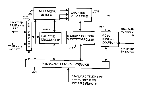
To more particularly describe the functionality of the IMD 102 refer now
to Figure 3 which is a block diagram of IMD 102. The IMD 102 comprises
several components. The telephone line is coupled to a interface 202. The
interface 202 is coupled to an interactive control device 204 and a Caller ID
decode chip 206. The interactive control device 204 receives signals from a
CA 02207178 1997-06-0~
W O96/19066 PCTrUS95/16406
standard telephone keypad or a remote control. The interface 202 is coupled to
a multimedia memory 208 which can be an expandable dynamic random access
memory (DRAM) 208. The Caller ID decode chip 206 provides data
representing Caller ID information to the memory 108. The multimedia memory
208 provides data to graphics processor 210.
In addition, the output of the graphics processor 210 is provided to a video
control chip 212. Video control 212 provides signals to a standard television
display and receives signals from a standard television source. The Caller ID
decode chip 206, the multimedia memory 208, the graphics processor 210, the
video control 212 are all ultimately controlled by the microprocessor,
microcontroller 214 which manages the operation of all of the above elements.
The video control 212 is coupled to a standard telephone keypad input or for a
television remote-type device or a special IMD remote can be utilized in a variety
of ways which will be discussed in detail hereinafter.
Personalized and demographic information (such as the age, race, sex and
other personal characteristics) of the user along with the technical informationassociated with the IMD 102 (serial no., number of generators, type etc.).
The function of each of the different components in a preferred
embodiment is described in a sllmm~ry fashion below.
Interface Chip 202
CA 02207178 1997-06-05
W O96/19066 PCTAUS95/16406
A. Responsible for all c~"nll,unications between standard phone line, optional
serial port, interface to multimedia memory, multimedia decode, audio control,
and processor control modules.
B. Supports standards protocol for half-duplex, full duplex, and half-duplex
S high speed operation.
C. On-chip encode/decode capability, D/A, AJD for voice, fAcsimile, and data
functions.
D. Dual tone multi-frequency (DTMF) detect and generation.
Caller ID Decode Chip 206
A. Responsible for real-time Caller ID information to extract data from
processing in subsequent operations.
Multimedia Memory 208
A. Nominal DRAM or VRAM for image mixing/processing, and
multimedia data store.
B. Nominal ROM for resident IMD control prograrn.
C. Optional co-resident DRAM for multimedia data store and program/data
store.
D. Optional non-volatile storage (extendible).
E. Memory control unit for VRAM/ROM/DRAM and non-volatile storage.
CA 02207178 1997-06-0~
W O96/19066 PCT/US95tl6406
Video Control Chip 212
a. Responsible for all IMD 102 video mixing, enhancements, and display
functions.
B. Pixel processor for mix, zoom, pan, chroma key, transform on pixel data,
transitions.
C. Graphics processor for figures (e.g., rectangles with color fill) generation,sprites, text with foreign characters, and scrolling.
D. Digital to analog conversion, analog to NTSC, NTSC video plus stereo
audio to RF.
Graphics Processor 210
~. Responsible for enhancing received analog/digital audio, music synthesis
generation, and overall analog mixing and audio effects.
B. Incorporates decoding burden.
C. Sampled instrument synthesis from compressed MIDI input.
D. Built-in micro-controller for multi-task generation.
E. Dual analog source mix, digital audio and synthesizer mix, analog audio
control (volume, bass, treble, balance) for output to analog left/right audio.
Microprocessor/Microcontroller 214
A. Responsible for multi-task execution of resident and downloaded IMD
code for operation in conjunction or independently of the MCPS.
-10-
CA 02207178 1997-06-0~
W O 96119066 PCT/US95/16406
B. Master/slave microcontroller architecture for multi-task control of
communications, multimedia memory, multimedia decode, digital video control,
digital audio/synthesis, and interface management.
Referring now to the flow chart Figure 4 the Caller ID system 100
S operates in the following manner. Initially, the phone rings, via step 302. The
Caller ID decoder 206, decodes the Caller ID information and provides it to
memory 208, via step 304. The memory 208 under control of controller 212 cross
references the number information to name information within the memory 208,
via step 306. If the number is cross-referenced to a name, then the name and
telephone numbers are displayed, via step 308 on the television screen. ~ a
the other hand, the number is not cross-referenced only the number will be
displayed, via step 310. The display will end after the phone stops ringing withstep 312.
Through this system, the Caller ID information is displayed directly on a
television screen. Therefore, the user need not go directly to the telephone to
observe the display on the telephone.
The caller name information is updatable through the use of a keypad or
remote control of the TV or the remote control of the device.
Accordingly, through this system a name could be added through a voice
response system activated through the interactive control system, through the use
of the keypad of the telephone itself and/or through a remote control or the like
the name information can be added to the memory. This system also allows for
choosing a letter or number by utilizing a keypad on the telephone or a remote
CA 02207178 1997-06-0~
W O96/19066 PCTrUS95/16406
control. A user can visually ascertain the choice on television such that errorscan be immediately elimin~ted by utilizing a specialized key on the telephone orremote control as a erase, delete or backspace key.
Another critical feature of the IMD 102 is to have a remote control that
S will work in conjunction with the TV or other display or the like to provide
enhanced multimedia information. To more fully explain this feature refer now
to Figure 5. The remote control 900 looks much like a telephone keypad. It has
the numerals (0-9) and symbols (*-#) that are part of an ordinary telephone
keypad. It includes an enter key 902 that is typically utilized to change
information or change channels in the case of a television set. The control 900
would also include a volume key 904 and a channel or memory select key 906, a
connect key 908 and a multimedia toggle button 910. It could also include a
credit card slot 912. This credit card slot 912 would be utilized by the viewer to
allow for the purchase of certain items directly while viewing the television screen.
Finally, the control 900 includes special effect keys 916, for example, for allowing
for the browsing of a multimedia directory while simultaneously displaying a
picture in the picture of the current broadcast TV channel.
The remote control 900 could utilize a radio frequency signal or audio
signal to interact with the receiver and/or IMD 102 for the control of the IMD,
control the selection of multimedia information, and for the control of other
household devices. It is also known that a more conventional remote control
could be utilized such as one that controls a VCR or a television and its use
would be within the spirit and scope of the present invention.
CA 02207178 1997-06-05
W O96119066 PCTrUS95/16406
Although the present invention has been described in accordance with the
embodiments shown in the figures, one of ordinary skill in the art recognizes
there could be variations to the embodiments and those variations would be
within the spirit and scope of the present invention~ Accordingly, many
S modifications may be made by one of ordinary skills in the art without departing
from the spirit and scope of present invention, the scope of which is defined
solely by the appended claims.