Language selection

Search

Patent 2207695 Summary

Third-party information liability

Some of the information on this Web page has been provided by external sources. The Government of Canada is not responsible for the accuracy, reliability or currency of the information supplied by external sources. Users wishing to rely upon this information should consult directly with the source of the information. Content provided by external sources is not subject to official languages, privacy and accessibility requirements.

Claims and Abstract availability

Any discrepancies in the text and image of the Claims and Abstract are due to differing posting times. Text of the Claims and Abstract are posted:

  • At the time the application is open to public inspection;
  • At the time of issue of the patent (grant).
(12) Patent: (11) CA 2207695
(54) English Title: VERTICAL BLIND ASSEMBLY
(54) French Title: UNITE DE STORES VERTICAUX
Status: Deemed expired
Bibliographic Data
(51) International Patent Classification (IPC):
  • E06B 9/36 (2006.01)
(72) Inventors :
  • WENG, MING LU (Taiwan, Province of China)
(73) Owners :
  • TSER-WEN CHOU (United States of America)
(71) Applicants :
  • TSER-WEN CHOU (United States of America)
(74) Agent: KIRBY EADES GALE BAKER
(74) Associate agent:
(45) Issued: 2000-01-11
(22) Filed Date: 1997-06-13
(41) Open to Public Inspection: 1997-12-18
Examination requested: 1997-06-13
Availability of licence: N/A
(25) Language of filing: English

Patent Cooperation Treaty (PCT): No

(30) Application Priority Data:
Application No. Country/Territory Date
666,612 United States of America 1996-06-18

Abstracts

English Abstract


A vertical blind assembly includes two housings
secured together so as to form a carrier frame. Two
worm gears are rotatably received in the housings and
engaged with each other. A post is coupled to one of
the worm gears for rotating the worm gear. A beam is
slidably engaged in the other gear so as to be rotated
by the post. A number of casings each includes a gear
slidably engaged on the beam and each includes a pole
rotated by the gear and for supporting slats. The
casings are secured to the housings by a number of
couplers which may be easily disengaged from the
housings.


French Abstract

Unité de stores verticaux comprenant deux boîtiers fixés ensemble pour former un châssis. Deux engrenages à vis sans fin viennent se loger en tournant dans les boîtiers et sont engagés l'un avec l'autre. Une tige est couplée à l'un des engrenages à vis sans fin pour le faire tourner. Un cylindre glisse dans l'autre engrenage pour être tourné par la tige. Chacun des châssis comprend un engrenage qui glisse sur le cylindre ainsi qu'une tringle qui tourne au moyen de l'engrenage et qui soutient les lames. Les châssis sont fixés aux boîtiers par plusieurs manchons de raccordement qui peuvent être facilement retirés des boîtiers.

Claims

Note: Claims are shown in the official language in which they were submitted.


I CLAIM:
1. A vertical blind assembly comprising:
a first housing and a second housing secured
together so as to form a carrier frame, said first and
said second housings each including a room formed
therein and each including a vertical opening formed
therein and each including a lateral opening formed
therein, said first and said second housings each
including a vertical slot formed therein and each
including at least one wheel rotatably secured thereto,
a rod rotatably received in said vertical openings
of said first and said second housings and including a
first worm gear formed thereon and rotatably received
in said rooms of said first and said second housings,
a shaft rotatably received in said lateral
openings of said first and said second housings and
including a second worm gear formed thereon and
rotatably received in said rooms of said first and said
second housings for engaging with said first worm gear,
said shaft including an engaging channel formed
therein,
a post coupled to said rod for rotating said rod
and said first and said second worm gears,
a beam engaged in said engaging channel of said
shaft and arranged for allowing said shaft to be
slidably engaged on said beam and for allowing said
shaft and said beam to be rotated in concert with each


other,
a plurality of casings each including a pole
rotatably supported therein for engaging with and for
supporting a vertically oriented slat, said pole
including a third gear provided on top thereof and
rotatably received in said casing,
a plurality of barrels each being laterally and
rotatably supported in said casing and each including
an outer peripheral portion having a fourth gear
provided thereon for engaging with said third gear and
for rotating said pole, said barrel being slidably
engaged on said beam and rotated in concert with said
beam, and
a plurality of couplers each including a lower
portion having a ring provided thereon for engaging
with said pole and each including an upper portion
having a catch provided thereon for engaging with said
casing so as to secure said coupler to said casing,
said couplers each including an engaging member for
engaging with said slot of said first and said second
housings so as to couple said casing to said first and
said second housings,
said first worm gear being rotated by said post in
order to rotate said second worm gear and said beam and
said fourth gear and said third gear, so as to rotate
said pole and said slat.
2. A vertical blind assembly according to claim 1,


wherein said second housing includes at least one
engaging hole formed therein, said first housing
includes at least one hook for engaging with said
engaging hole of said second housing so as to secure
said first and said second housings together.
3. A vertical blind assembly according to claim 1,
wherein said shaft includes a plurality of spaced ribs
formed therein so as to engage with said beam and so as
to allow said shaft and said beam to be rotated in
concert with each other.
4. A vertical blind assembly according to claim 1,
wherein said barrel includes a plurality of flanges
formed therein for engaging with said beam so as to
allow said barrel and said beam to be rotated in
concert with each other.


Description

Note: Descriptions are shown in the official language in which they were submitted.


CA 0220769~ 1997-06-13


TITLE: VERTICAL BLIND ASSEMBLY
BACKGROUND OF THE INVENTION
1. Field of the Invention
The present invention relates to a vertical blind,
05 and more particularly to a vertical blind assembly.
2. Description of the Prior Art
A typical vertical blind assemblY is disclosed in
US Patent No. 4,848,435 to Helver and comprise a
carrier assembly having an integral carrier frame for
receiving a number of gears and a worm gear therein.
The carrier assembly includes a complicated
configuration such that the gears and the worm gear may
not be easily engaged in the carrier frame.
The present invention has arisen to mitigate
and/or obviate the afore-described disadvantages of the
conventional vertical blind assemblies.
SUMMARY OF THE INVENTION
The primary objective of the present invention is
to provide a vertical blind assembly which includes a
simplified configuration that is excellent for
assembling purposes.
The other objective of the present invention is to
provide a vertical blind assembly which includes a
casing that may be easily engaged with and disengaged
from the carrier frame.
In accordance with one aspect of the invention,
there is provided a vertical blind assembly comprising


CA 0220769~ 1997-06-13


a first housing and a second housing secured together
so as to form a carrier frame, the first and the second
housings each including a room formed therein and each
including a vertical opening formed therein and each
05 including a lateral opening formed therein, the first
and the second housings each including a vertical slot
formed therein and each including at least one wheel
rotatably secured thereto, a rod rotatably received in
the vertical openings of the first and the second
housings and including a first worm gear formed thereon
and rotatably received in the rooms of the first and
the second housings, a shaft rotatably received in the
lateral openings of the first and the second housings
and including a second worm gear formed thereon and
rotatably received in the rooms of the first and the
second housings for engaging with the first worm gear,
the shaft including an engaging channel formed therein,
a post coupled to the rod for rotating the rod and the
first and the second worm gears, a beam engaged in the
engaging channel of the shaft and arranged for allowing
the shaft to be slidably engaged on the beam and for
allowing the shaft and the beam to be rotated in
concert with each other, a plurality of casings each
including a pole rotatably supported therein for
engaging with and for supporting a vertically oriented
slat, the pole including a third gear provided on top
thereof and rotatably received in the casing, a


CA 0220769~ 1997-06-13


plurality of barrels each being laterally and rotatably
supported in the casing and each including an outer
peripheral portion having a fourth gear provided
thereon for engaging with the third gear and for
05 rotating the pole, the barrel being slidably engaged on
the beam and rotated in concert with the beam, and a
plurality of couplers each including a lower portion
having a ring provided thereon for engaging with the
pole and each including an upper portion having a catch
provided thereon for engaging with the casing so as to
secure the coupler to the casing, the couplers each
including an engaging member for engaging with the slot
of the first and the second housings so as to couple
the casing to the first and the second housings. The
first worm gear is rotated by the post in order to
rotate the second worm gear and the beam and the fourth
gear and the third gear, so as to rotate the pole and
the slat.
The second housing includes at least one engaging
hole formed therein, the first housing includes at
least one hook for engaging with the engaging hole of
the second housing so as to secure the first and the
second housings together.
The shaft includes a plurality of spaced ribs
formed therein so as to engage with the beam and so as
to allow the shaft and the beam to be rotated in
concert with each other.


CA 0220769~ 1997-06-13


The barrel includes a plurality of flanges formed
therein for engaging with the beam so as to allow the
barrel and the beam to be rotated in concert with each
other.
05 Further objectives and advantages of the present
invention will become apparent from a careful reading
of a detailed description provided hereinbelow, with
appropriate reference to accompanying drawings.
BRIEF DESCRIPTION OF THE DRAWINGS
FIG. 1 is an exploded view of a vertical blind
assembly in accordance with the present invention;
FIG. 2 is a partial exploded view of the vertical
blind assembly;
FIG. 3 is a cross sectional view taken along lines
3-3 of FIG. 2;
FIG. 4 is a cross sectional view taken along lines
4-4 of FIG. 2;
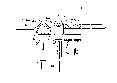
FIG. 5 is a plane view illustrating the coupling
of the casing to the carrier frame;
FIG. 6 is a top view of the vertical blind
assembly; and
FIG. 7 is a schematic view illustrating the
operation of the vertical blind assembly.
DETAILED DESCRIPTION OF T~E PREFERRED EMBODIMENT
Referring to the drawings, and initially to FIGS.
1 to 4, a vertical blind assembly in accordance with
the present invention comprises a carrier frame

CA 0220769~ 1997-06-13


including a first housing 10 and a second housing 20
which are secured together so as to form the carrier
frame. The housings 10, 20 each includes a room 11, 21
formed therein for receiving two worm gears 31, 41
05 therein. The housings 10, 20 each includes a vertical
opening 12, 22 for rotatably receiving a rod 30 therein
and each includes a lateral opening 13, 23 formed
therein for rotatably receiving a shaft 40 therein. The
worm gears 31, 41 are formed on the rod 30 and the
shaft 40 respectively. A post 32 is coupled to the rod
30 for rotating the rod 30. The housings 10, 20 each
includes a T-shaped slot 14, 24 vertically formed
therein and each includes two spindles 15, 25 provided
on the outer portion for supporting wheels 16, 26
thereon which are engaged in the typical track 90 of
the vertical blind (FIG. 7). The housings 10, 20 each
includes a recess 17, 27 formed therein for slidably
receiving a spacer strip 50 therein. The housing 10
includes a number of hooks 18, 19 for engaging with the
engaging holes 28t 29 of the other housing 20 so as to
secure the housings 10, 20 together. The shaft 40
includes an engaging channel 42 formed therein and
defined by a number of spaced ribs 43 so as to engage
with a cross shaped beam 44.
A number of casings 51 each includes a pole 52
rotatably supported therein for engaging with and for
supporting a vertically oriented slat or louver 58. The

CA 0220769~ 1997-06-13


pole 52 includes a gear 53 provided on top thereof and
rotatably received in the casing 51. A barrel 54 is
laterally and rotatably supported in the casing 51 and
includes a gear 55 provided on the outer peripheral
05 portion thereof for engaging with the gear 53 and for
rotating the pole 52. The barrel 54 includes a number
of flanges 56 formed therein (FIG. 2) for engaging with-
the beam 44 such that the barrel 54 may be rotated by
the beam 44.
As best shown in FIGS. 5 to 7, a number of
couplers 60 each includes a ring 61 provided in the
lower portion for engaging with the pole 52 of the
casing 51 and each includes a catch 62 provided on top
thereof for engaging with the upper portion of the
casing 51 such that the couplers 60 may be easily
secured to the casing 51. The couplers 60 each includes
a T-shaped engaging member 63 for engaging with the T-
shaped slot 14, 24 of the housings 10, 20 such that the
casings 51 may be easily coupled to the housings 10,
20.
In operation, the worm gear 41 may be rotated by
the post 32 via the worm gear 31, such that the beam 44
and the barrel 54 and the gear 55 may also be rotated
by the shaft 40. The pole 52 and the slàt 58 may thus
be rotated by the engagement of the gears 53, 55. As
shown in FIG. 7, the housings 10, 20 and the casing 51
may be pulled and caused to move along the trac~ 90 by


CA 0220769~ 1997-06-13


the post 32.
It is to be noted that the casing 51 may be easily
coupled to the housings 10, 20 by the coupler 60 and
may be easily disengaged from the housings for
05 repairing purposes. It is further to be noted that the
end portions of the shaft 40 can be easily and stably
engaged in the lateral openings 13, 23 of the housings
10, 20 when the housings 10, 20 are secured together.
The vertical blind assembly includes a simplified
configuration that is excellent for assembling
purposes.
Accordingly, the vertical blind assembly in
accordance with the present invention includes a
simplified configuration for facilitating assembling
operations of the vertical blind assembly and includes
a casing that may be easily secured to the housings for
repairing purposes.
Although this invention has been described with a
certain degree of particularity, it is to be understood
that the present disclosure has been made by way of
example only and that numerous changes in the detailed
construction and the combination and arrangement of
parts may be resorted to without departing from the
spirit and scope of the invention as hereinafter
claimed.

Representative Drawing
A single figure which represents the drawing illustrating the invention.
Administrative Status

For a clearer understanding of the status of the application/patent presented on this page, the site Disclaimer , as well as the definitions for Patent , Administrative Status , Maintenance Fee  and Payment History  should be consulted.

Administrative Status

Title Date
Forecasted Issue Date 2000-01-11
(22) Filed 1997-06-13
Examination Requested 1997-06-13
(41) Open to Public Inspection 1997-12-18
(45) Issued 2000-01-11
Deemed Expired 2008-06-13

Abandonment History

There is no abandonment history.

Payment History

Fee Type Anniversary Year Due Date Amount Paid Paid Date
Request for Examination $200.00 1997-06-13
Registration of a document - section 124 $100.00 1997-06-13
Application Fee $150.00 1997-06-13
Maintenance Fee - Application - New Act 2 1999-06-14 $50.00 1999-04-27
Final Fee $150.00 1999-10-08
Maintenance Fee - Patent - New Act 3 2000-06-13 $50.00 2000-06-01
Maintenance Fee - Patent - New Act 4 2001-06-13 $50.00 2001-06-11
Maintenance Fee - Patent - New Act 5 2002-06-13 $75.00 2002-05-28
Maintenance Fee - Patent - New Act 6 2003-06-13 $75.00 2003-05-26
Maintenance Fee - Patent - New Act 7 2004-06-14 $100.00 2004-06-08
Maintenance Fee - Patent - New Act 8 2005-06-13 $100.00 2005-05-25
Maintenance Fee - Patent - New Act 9 2006-06-13 $100.00 2006-05-09
Owners on Record

Note: Records showing the ownership history in alphabetical order.

Current Owners on Record
TSER-WEN CHOU
Past Owners on Record
WENG, MING LU
Past Owners that do not appear in the "Owners on Record" listing will appear in other documentation within the application.
Documents

To view selected files, please enter reCAPTCHA code :


To view images, click a link in the Document Description column. To download the documents, select one or more checkboxes in the first column and then click the "Download Selected in PDF format (Zip Archive)" or the "Download Selected as Single PDF" button.

List of published and non-published patent-specific documents on the CPD .

If you have any difficulty accessing content, you can call the Client Service Centre at 1-866-997-1936 or send them an e-mail at CIPO Client Service Centre.


Document
Description 
Date
(yyyy-mm-dd) 
Number of pages   Size of Image (KB) 
Cover Page 1998-02-09 1 43
Cover Page 1999-12-22 1 44
Abstract 1997-06-13 1 15
Description 1997-06-13 7 214
Claims 1997-06-13 3 79
Drawings 1997-06-13 5 104
Representative Drawing 1999-12-22 1 9
Representative Drawing 1998-02-09 1 9
Assignment 1997-06-13 3 81
Correspondence 1997-08-22 1 29
Correspondence 1999-10-08 1 38
Assignment 1998-05-11 4 120