Note: Descriptions are shown in the official language in which they were submitted.
i ~ CA 02208122 1997-06-19
s ~ I
MACH-ZEHNDER INTERFEROMETRIC DEVICES
WITH COMPOSITE FIBERS
S Background Of The Invention
The present invention relates to Mach-Zehnder
interformetric devices and to methods of making the same.
Optical fiber communication systems require
wavelength selection devices for various purposes. For
example, in a wavelength division multiplexing transmission
scheme, a single fiber may carry several beams of light at
slightly different wavelengths. Each beam carries a
separate stream of information. A wavelength selective
filter is used at a point where the fiber branches to direct
one beam at a particular wavelength onto one branch of the
fiber and to direct the other beams onto the other branch.
Several receivers belonging to different telecommunications
customers can be connected to a single fiber. Each receiver
is equipped with a filter adopted to direct only a very
narrow band of wavelengths to that device and to exclude all
others. Signals intended for the particular subscriber are
sent at the wavelength associated with that subscriber.
- These and other wavelength selective devices must
meet demanding requirements for use in practical
25 communications systems. The devices should be capable of
separating wavelengths differing from one another by only a
few nanometers. The wavelength selectlve device should be
environmentally stable, reliable and durable. In some
applications, the wavelength selective device should be
~ - CA 02208122 1997-06-19
. , ~ '' '. '
-2--
"tunable" or adjustable to vary the wavelengths which it
selects. Also, the wavelength selective device should
operate with a relatively low loss of optical power, i.e.,
the device should not dissipate substantial amounts of the
optical power supplied to it.
Mach-Zehnder interferometers have been utilized as
wavelength selective devices in optical communication
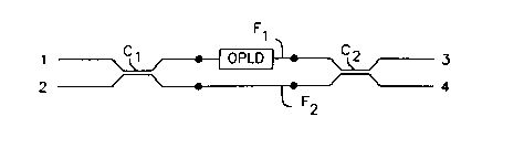
systems. As depicted in Figure 1, a Mach-Zehnder
interferometer includes a pair of fibers F1 and F2. The
fibers are coupled to one another for light transfer
therebetween at a first coupler C1 and a second couple C2.
The couplers are arranged to transfer light, one fiber to
the other. As further explained below, the couplers may be
so-called "evanescent" couplers in which narrowed, elongated
portions of the fibers are closely juxtaposed with one
another within a matrix or outer coating. The couplers may
be 3dB couplers, arranged to transfer approximately one-half
of the optical power supplied on one fiber to the other
fiber. Fibers F1 and F2 have phase shift regions with
different optical path lengths disposed between the
couplers. Thus, the optical path length over the phase
shift region in fiber F1 is different from the optical path
length over the phase shift region in fiber F2. As used in
this disclosure, the term "optical path length" is a measure
of the time required for light at a given wavelength and in
a given propagation mode to pass through the fiber from one
end to the other. The optical path length difference has
been provided either by making the phase shift region of one
fiber physically longer than the other, or by making the two
fibers F1 and F2 with different propagation constants so
that the velocity of light within the two fibers is
different. The latter structure can be effected by making
the fibers with different refractive index profiles. Where
the fibers are "step-index" fibers, incorporating a core
having a relatively high refractive index and a coating with
CA 02208122 1997-06-19
--3-
a relatively low refractive index overlying the core, the
two fibers may have cores of different refractive indices,
different core diameters, different coating refractive
indices or some combination of these. Regardless of the
particular mechanism used to produce the optical path length
difference, the single stage Mach-Zehnder filter depicted in
Fig 1 will direct light supplied through input 1 either to
output 3 or to output 4 depending upon the wavelength of the
light. More complex Mach-Zehnder devices utilize multiple
stages with multiple phase shift regions and multiple
couplers connected in series to achieve certain desirable
wavelength-selective characteristics. Still other Mach-
Zehnder devices incorporate more than two fibers connected
in parallel between the couplers, as described in United
States Patent No. 5,351,325, the disclosure of which is
hereby incorporated by reference herein. The various
optical fibers incorporate different optical path lengths.
Desirably, the optical path length differences are selected
to provide optical path length differences which are
rational or integral multiples of one another.
For Mach-Zehnder devices to provide the desired
wavelength-selective characteristics, the path length
differences should be as specified in the design device and
should remain stable except when deliberately altered.
Environmental effects, such as movement or vibration of the
individual fibers, and differential heating or cooling of
the fibers can severely degrade the performance of Mach-
Zehnder components. United States Patent No. 5,295,205
('the '205 patent"), the disclosure of which is also hereby
incorporated by reference herein, discloses an improved
Mach-Zehnder device incorporating an elongated body of a
matrix glass formed as a hollow tube. The optical fibers
extend through the bore of the tube. Each coupler may be
formed by collapsing a portion of the tube onto the fibers,
as by heating it, and then stretching a portion of the
collapsed tube, and portions of the fibers contained
CA 02208122 1997-06-19
-4--
therein, to provide narrowed, elongated sections in the
fibers surrounded by the matrix glass. This general
approach can be utilized to form a wide variety of Mach-
Zehnder components, including those having more than two
S fibers and staged devices having more than two couplers.
The devices formed in accordance with preferred embodiments
of the '205 patent are securely encased within the matrix
glass tube and hence are substantially insensitive to
temperature gradients and undesired, inadvertent bending.
The preferred devices formed according to the '205 patent,
therefore, can be used as components in practical
telecommunication systems.
Despite these and other advances in the art, there is
a need for further improvement. Manufacture of Mach-Zehnder
devices using fibers with different propagation constants
requires the manufacturer to stock fibers having different
propagation constants. When more than two fibers are
employed in a single device, the fibers must be made with
propagation constants having the desired relationship to one
another. For some designs, the fibers must be made in sets
with differences between propagation constants such that the
differences are integral multiples of one another. This
imposes significant constraints and costs in the fiber
drawing process. Moreover, the adjustments to the fibers
required to achieve the desired propagation constants can
have undesirable side effects. For example, adjustment of
the fiber core composition to yield a particular propagation
constant can yield a fiber having a particularly soft core
which forms to an elliptical cross-section during the
stretching process used to form the couplers. This, in
turn, can result in optical performance which varies with
the polarization of the light transmitted through the
device. Accordingly, further improvements in methods of
making Mach-Zehnder devices and in the resulting devices
would be desirable.
- CA 02208122 1997-06-19
. ' '
-5-
Summary Of The Invention
One aspect of the invention provides methods of
making a Mach-Zehnder device. Methods in accordance with
this aspect of the invention desirably include the step of
providing a plurality of optical fibers including at least
one composite fiber. Each such composite fiber includes a
pair of coupling regions and a phase shift region. The
phase shift region of each composite fiber has a propagation
constant different from the propagation constant of the
coupling regions in that fiber. Methods in accordance with
this aspect of the invention desirably also include the step
of forming a pair of optical couplers at spaced apart
locations on the fibers so that the phase shift region of
each composite fiber is disposed between the couplers. The
step of providing each composite fiber may be performed by
splicing a piece of a second stock fiber between pieces of
a first stock fiber. In addition to the composite fiber or
fibers, the plural fibers used to form the Mach-Zehnder
device may include a uniform fiber having the same
propagation constant throughout its length. Most
preferably, the uniform fiber is formed entirely from a
piece of the first stock fiber used to make each composite
fiber.
Because the second stock fiber is found only in the
phase shift regions of the composite fiber or fibers, the
- second stock fiber is not subjected to the coupler-forming
process and it does not form any portion of the couplers.
Therefore, the characteristics of the second stock fiber can
be selected without regard for its performance in the
coupler-forming process. The optical path length of the
composite fiber depends upon the length of the piece of
second stock fiber incorporated in the composite fiber.
Thus, the optical path length of the composite fiber can be
controlled by controlling the length of the second stock
fiber piece incorporated in the composite fiber, without
- CA 02208122 1997-06-19
. ~ ', ' .'
affecting the overall physical length of the fiber between
the couplers. Preferably, all of the fibers have the same
overall length between the couplers. The length of the
piece of second stock fiber which forms the phase shift
region of each composite fiber can be adjusted to compensate
for deviations of any fiber propagation constants from
nominal values. Where the process is used to form a Mach-
Zehnder device with more than two fibers extending between
the couplers, the plurality of optical fibers may include a
plurality of composite fibers. Here again, àll of the
fibers may have the same physical length between the
couplers. The optical path lengths of the composite fibers
are directly related to the lengths of the pieces of second
fiber incorporated in each such composite fiber. Therefore,
precise relationships between the optical path length
differences between the various fibers can be achieved
readily without any need to make special fibers with
numerous different propagation constants. Most preferably,
all of the uniform and composite fibers are formed entirely
from the same first and second stock fibers.
In particularly preferred arrangements of the
invention, the step of forming the couplers includes the
step of encasing the fibers in a matrix glass and elongating
the fibers to form narrow sections extending alongside one
another within the matrix glass. Preferably, only the
coupling regions of the composite fibers and portions of the
uniform fiber, where used, are elongated to form the
couplers . Most preferably, the step of encasing the fibers
in a matrix glass is performed by disposing the fibers in
the bore of a tube of the matrix glass and collapsing the
tube onto the fibers to form collapsed regions, and the step
of elongated the fibers includes the step of elongating a
portion of each collapsed region and the fiber portions
disposed therein. These steps of the process may be
performed in accordance with the aforementioned '205 patent.
A further aspect of the present invention provides a
- CA 02208122 1997-06-19
-7-
Mach-Zehnder device including plural optical fibers. The
plural fibers include at least one composite fiber, each
such composite fiber including a pair of coupling regions
and a phase shift region. The phase shift region of each
S composite fiber has a propagation constant different from
the propagation constant of the coupling regions of the
fiber. The device according to this aspect of the present
invention includes a pair of optical couplers at
spaced-apart locations on the fibers, the phase shift region
of each composite fiber being disposed between thè couplers.
Most preferably, all of the fibers have substantially equal
total length between the couplers. The plural fibers
desirably include a base fiber such as a uniform fiber
having the same propagation constant throughout its length.
The coupling region of each composite fiber may have a
propagation constant substantially equal to the propagation
constant of the uniform fiber, and the phase shift region of
each composite fiber may have a propagation constant
different than the propagation constant of the uniform
fiber. Thus, the optical path length difference of each
composite fiber relative to the base or uniform fiber
depends upon the length of the phase shift region in the
composite fiber. Preferably, the propagation constants of
the phase shift regions of all of the composite fibers are
equal to one another and hence the magnitude of the phase
shift in each composite fiber relative to the uniform fiber
will be directly proportional to the length of the phase
shift region of each composite fiber. Where plural
composite fibers are employed, the lengths of the phase
shift regions of the various composite fibers may be
rational multiples of one another and preferably, integral
multiples of one another. Desirably, the device is formed
as a monolithic Mach-Zehnder device incorporating a tube of
matrix glass surrounding the fibers and forming the matrix
of the couplers.
These and other objects, features and advantages of
CA 02208122 1997-06-19
., ~
the present invention will be more readily apparent from the
detailed description of the preferred embodiments set forth
below, taken in conjunction with the accompanying drawings.
Brief Description Of The Drawings
Figure 1 is schematic diagram of a Mach-Zehnder
interferometer.
Figure 2 is a diagrammatic elevational view depicting
a fiber during one stage of the manufacturing process in
accordance with an embodiment of the invention. '
Figures 3, 4 and 5 are views similar to Fig. 2 but
depicting the fiber at later stages of the process.
Figure 6 is a sectional view depicting the Mach-
Zehnder device in accordance with one embodiment of the
invention.
Figure 7 is a graph depicting the power output
characteristics of the device of Fig. 6.
Figure 8 is a schematic illustration of an apparatus
utilized in manufacture of the device of Fig. 6.
Figure 9 is a view similar to Fig. 6 but depicting a
device in accordance with a further embodiment of the
invention.
Figure 10 is a diagrammatic view of an assemblage of
fibers utilized in a process according to a further
embodiment of the invention.
Figure 11 is a sectional view depicting the
Mach-Zehnder device made from the fibers shown in Fig. 10.
~ CA 02208122 1997-06-19
Detailed Description of the Preferred Embodiments
Referring to Figures 2-5, a process in accordance
with one embodiment of the invention begins with a piece 106
of a first stock optical fiber. In the particular
arrangement illustrated, the first stock fiber is a step-
index glass optical fiber of the type having a core 102 with
relatively high refractive index and a coating 104 with a
relatively low refractive index surrounding the core. The
fiber also has a conventional polymeric coating 108
surrounding the glass coating. The first stock fiber is
severed to form piece 106. Coating 108 is removed in the
region adjacent the severed face. The length of piece 106
is not critical to the process; it merely must be long
enough to accommodate formation of the couplers as discussed
below. In the next stage of the process, a second stock
fiber is cut to provide a piece 110 having a working length
Lw. The second stock fiber is also a step-index fiber having
a core 112 and coating 114. Any polymeric overcoating is
removed from piece 110. The second stock fiber has a
propagation constant ~ different from the propagation
constant of the first stock fiber. Thus, at least one
parameter of the second stock fiber which influences the
propagation constant of light transmitted therein is
- different from the corresponding parameter of the first
fiber. Most preferably, the diameter of core 112 is the
same as the diameter of core 102 in the first stock fiber.
However, the refractive index of core 112 may differ from
that of core 102. Also, the refractive index of second
fiber coating 114 may differ from the refractive index of
first fiber coating 104. Piece 110 is spliced to piece 106
at a joint 116. The splicing process used to form joint 116
should provide sufficient time at elevated temperature to
allow diffusion between cores 102 and 112, and thereby form
a gradual transition between the two cores. This minimizes
losses in optical power at the joint. Most preferably, the
- CA 02208122 1997-06-19
-10-
joint has a loss less than about 0.2 dB. After formation of
joint 116, second fiber piece 110 is cleaved to the desired
phase shift region length Lps~ This length is measured from
joint 116 and controlled as precisely as possible. The
length Lp5 is selected to provide the desired optical
performance in the finished device as discussed further
below. A second piece 118 of the first fiber used to form
piece 106 is cut and joined with piece 110 at a second joint
- 120. The length of fiber piece 118 is also not critical. Here again, the joint is formed with a diffusèd, gradual
interface to suppress losses at joint 120. Conventional
fusion splicing equipment can be used to make joints 116 and
120. The joining procedures result in a composite fiber 122
with two pieces 106 and 118 of the first fiber and a piece
110 of the second fiber spliced therebetween . The first
fiber pieces 106 and 118 form coupling regions of the
composite fiber, whereas the second fiber piece 110 forms
the phase shift region.
The composite fiber is then terminated to provide the
types of end terminations required in the final product.
For example, where an end 124 of the composite fiber is to
- be connected to an input or output of the Mach-Zehnder
device, it is severed and prepared for joining in the normal
manner. Alternatively, where an end 126 is to remain
unconnected, it can be provided with an anti-reflection
termination in accordance with the teachings of U.S. Patent
No. 4,979,972. Thus, coupling region 118 is heated and
pulled to sever it and then further heated to cause the
glass to form a ball-like rounded end face having a diameter
equal to or slightly smaller than the original outer
diameter of the fiber coating.
Composite fiber 122 is then formed into a monolithic
device including this composite fiber together with a
uniform fiber 130 (Fig. 6). Uniform fiber 130 is another
piece of the same first fiber used to form the coupling
CA 02208122 1997-06-19
. ~
regions 106 and 118 in the composite fiber. Thus, the
uniform fiber has the same propagation constant as the
coupling regions of the composite fiber. The steps in the
device formation process after formation of the composite
S fiber may be substantially identical to the steps used in
forming a Mach-Zehnder device according to the
aforementioned U.S. Patent No. 5,295,205. Thus, the Mach-
Zehnder device (Fig. 6) is formed as a monolithic structure
that contains concatenated overclad couplers 11 and 12 that
are joined by a phase shifting region 14. Phase shifting
region 14 includes the phase shift region 110 of the second
fiber. The device is formed by inserting composite fiber
122 and uniform fiber 130 (with overcoating removed) into
the bore 18 of a tube of matrix glass 19. The refractive
index of that portion of the matrix glass tube adjacent the
fibers is less than the lowest refractive index of the fiber
coating 104. The bore can be provided with funnels (not
shown) at each end to facilitate insertion of the fibers.
The combination of tube and fibers is referred to as a
coupler preform.
The coupler preform can be further processed in the
draw apparatus of Fig. 8. Preform 31 is inserted through
ring burner 34 and is clamped to draw chucks 32 and 33 which
are mounted on motor controlled stages 45 and 46. The fibers
are threaded through the vacuum attachments 41 and 41' which
are then sealed to the ends of preform 31. Typical vacuum
attachments are disclosed in U.S. Patent No. 5,011,251 which
is incorporated herein by reference. Vacuum is supplied to
tube 41 through line 42. One end of a length of thin rubber
tubing 43 is attached to that end of vacuum attachment 41
opposite preform 31; the remaining end of the tubing
extending within tube clamping means (not shown). Upper
vacuum attachment 41' is similarly associated with line 42',
tubing 43' and tube clamping means. Coated portions of the
fibers extend from tubing 43 and 43', the fiber portions
within the tube 19 between points a and b (Fig. 6) being
CA 02208122 1997-06-19
,
-12-
uncoated. When air pressure is directed against tubing 43
and 43' as indicated by arrows 44, 44', to clamp the tubing
against the fibers extending therethrough, bore 18 is
evacuated through lines 42 and 42'.
In one embodiment, that portion of the tube between
points a and b is initially collapsed onto the fibers. After
the preform is affixed to chucks 32 and 33 and the tube bore
is evacuated, the tube is heated near one end to cause it
to collapse at the region of applied heat. Chucks 32 and 33
move the preform relative to the burner to gradually extend
the collapsed region toward the opposite end of the preform
until the desired length of collapsed tube is obtained.
In an alternative process, chucks 32 and 33 can be
fixed, and burner 34 can be mounted on a motor controlled
stage 35. Burner 34 is initially positioned near one end of
the preform to cause it to collapse; stage 35 moves the
burner relative to the preform to extend the collapsed
region toward the preform's opposite end.
Thereafter, coupler 11 is formed near one end of the
preform by heating a region of the tube and moving computer
controlled stages 45 and 46 in opposite directions to
stretch the heated region. The tube stretching operation
can be performed in accordance with U.S. Patent No.
5,011,251. The rate at which the two tube ends move away
from each other constitutes the combined stretch rate. The
tube can be stretched at a constant rate, or the stretch
rate can vary continuously or in discrete steps. The
stretching operation can stop after a predetermined coupling
is achieved; thereafter, the tube can be reheated, and
stretching can occur at a second stretch rate. Coupler 11
is illustrated as having a constant diameter even though a
slight taper exists therein, whereby the longitudinal center
of the coupler exhibits the minimum diameter. It is well
- known that the coupling characteristics of the resultant
coupler are determined by such parameters as the optical and
mechanical characteristics of matrix glass 19 and fiber 130
.
CA 02208122 1997-06-19
-13-
and the coupler regions 106 and 118 of composite fiber 122.
The coupling characteristics can be influenced by coupler
parameters such as the length and shape of the neckdown and
tapered regions.
While stretching the tube to form the first coupler,
optical power can be coupled to an input optical fiber, and
the output signals can be monitored to control process steps
in the coupler manufacturing process. Alternatively, trial
devices can be fabricated using trial stretching distances
within this stage, and the optimum stretching distance can
be determined by measuring. In previous experience with
overclad fiber optic couplers, the total stretching
distance for both stages during the formation of each
coupler was usually between 12 and 16 mm.
For best performance as a filter or a WDM coupler,
couplers 11 and 12 have substantially identical coupling
characteristics. The second coupler 12 is therefore
preferably formed by subjecting the appropriate region of
the tube to stretching conditions that are identical to
those used to form the first coupler. Although couplers 11
and 12 can be achromatic or WDM type, the Mach-Zehnder
device will be useful over a wider wavelength range if
achromatic couplers are used. Various techniques can be
used to obtain achromaticity.
In accordance with U.S. Patent 5,268,979 entitled
"Achromatic Overclad Fiber Optic Coupler," a coupler can be
made to be achromatic if the refractive index n3 of the
matrix glass body surrounding the coatings of the fibers is
lower than the refractive index n2 of the coatings by such an
amount that the value of ~2-3 iS less than 0.125%, wherein ~2-
3 equals (n22-n32)/2n22.
For some applications, only one of the fibers of a
Mach-Zehnder filter needs to extend from the device at each
end. After the device is formed, those portions of fiber 17
that extend from the device may be severed. The severed
CA 02208122 1997-06-19
-14-
ends of fiber 17 are then preferably provided with
antireflection terminations as aforesaid.
As best seen in Fig. 6, coupler 11 includes only the
coupling region 106 of composite fiber 122 and an adjacent
portion of the uniform fiber 130, whereas coupler 12
includes the second coupler region 118 of the composite
fiber and a portion of uniform fiber 130. The phase shift
region 110 of the composite fiber is disposed between the
couplers, and is not elongated during the coupler formation
process. The resulting Mach-Zehnder device can be supplied
with light through an input end 132 and can deliver power at
a first output end 134 and a second output end 136. The
fraction of the input power appearing at the first output
end is a function of the wavelength of the applied light as
follows:
P=cos2{(~)(Lps)(d~ )}
~1)
where :
P equals the fraction of the output power appearing
at the first output port 134;
Lps is the length of phase shift region 110 in the
composite fiber;
d~ is the difference in propagation constant between
the phase shift region of the composite fiber and the
propagation constant of uniform fiber 130;
~ is the lower of the propagation constant of phase
shift region 110 and the propagation constant of the uniform
fiber 130; and
~ is the wavelength of the applied light.
For single-mode transmission where all fibers
transmit in the same mode, equation (1) can be restated as:
P=cos2{(~)(Lps)(dn/n)(1/~)}
(2)
Where:
n is the lower of the effective refractive index of
.
' - CA 02208l22 l997-06-l9
-15-
phase shift region 110 and the effective refractive index of
the uniform fiber 130; and
dn is the difference between the effective refractive
indices of the composite fiber and of uniform fiber 130.
The effect that different cores have on the effective
refractive index can be estimated by assuming half the power
of a single mode guide is in the core and by increasing the
delta (~) of a fiber. The effective index changes
-10 approximately as
dn/n=(~1-2+~1-2' ) /2
(3)
where ~1-2 equals (n12n22)/2n12) and A12, equals (n1'2-
n2/ 2~ / (2Ill 2), n1 and n1' being the refractive indices of cores
102 and 112 of the first and second fiber respectively.
Also n2 and n2' are the refractive indices of coatings 104
and 114 in the first and second fibers. The difference in
effective refractive index between fiber 130 and the phase
shift region 110 of composite fiber 122 would then be
dn/n = (~1-2 + ~1-2) /2 - 2-~12/2
(4)
= (~1-2' ~1-2) /2
Equation (4) can be inserted into equation (2) to
obtain
P=Cos2(~)(Lps)(~l-2l-Al-2)/~)
(5)
Equation (5) is plotted in Fig. 7 for a single-stage
Mach-Zehnder filter in which fiber 130 has a ~1-2 value of
0.3% and the phase shift region 110 of the composite fiber
has a ~1-2 value of 1.0%, the length LpsOf phase shift region
110 being lcm. At those wavelengths where P is a maximum,
substantially all of the light applied through first input
134 (less any losses in the device) is delivered to the
first output end 132. At those wavelengths where p is
CA 02208122 1997-06-19
,
-16-
.
approximately zero, substantially all of the light supplied
through input 134 to the device is delivered to the
terminated end 126 and dissipated.
Notably, the relationship between the output power
fraction P and wavelength ~ depends solely on the properties
of the fibers and the length Lps of phase shift region 110.
Because the optical properties of the coupling regions 106
and 118 of the composite fiber match the optical properties
of the uniform fiber 130, the lengths of the coupling
regions have no effect on the power function. ' Thus, the
distance between couplers 11 and 12 will have essentially no
impact on the performance of the device, so long as the
phase shift region 110 of the composite fiber is disposed
between the couplers. Accordingly, the coupler formation
process can be optimized to provide maximum coupler
performance without affecting the power function of the
coupler. Moreover, in mass production of couplers, the
power function of the devices can be optimized by adjusting
the length of phase shift region 110, without affecting any
other parameter of the device. For example, if the fibers
supplied to the process deviate somewhat from their nominal
compositions, the propagation constants of the fibers will
also differ from their nominal values. This will affect the
power function, causing an increase or decrease in the
separation between the peaks of the power function. This
can be corrected by increasing or decreasing the length Lps
of the phase shift region 110. Such compensation can be
achieved without altering the external dimension of the
finished product, and without changing the coupler formation
processes.
As disclosed, for example, in the aforementioned '205
patent, Mach-Zehnder devices can be concatenated in series,
to provide different filtering characteristics. One such
arrangement uses two devices, the second having an optical
path length difference or delay twice the optical path
CA 02208122 1997-06-19
-17-
length difference or delay of the other device. Only one
fiber of the first device is carried through into the
second; the other fiber is terminated. The resulting device
has a power function equal to the product of the power
functions of the individual devices, and hence has a power
function with widely separated peaks. Such a device may
employ a first composite fiber 122' ~Fig. 9) having a phase
shift region 110' and a second composite fiber 123' having
a phase shift region 111' twice the length of the first
phase shift region 110'. Each composite fiber~may have a
ball-terminated light blocking end 125'. The composite
fibers may be arranged end-to-end within the bore of a tube
19', with the light-blocking ends 125' of the fibers
adjacent one another. A uniform fiber 130' extends entirely
through the tube. Couplers 11' may be formed at four
locations along the tube, so as to provide a coupler on each
side of each phase shift region. Alternatively, the two
composite fibers 122' and 123' may be replaced by a single,
continuous composite fiber having both phase shift regions
110' and 111', and the single uniform fiber may be replaced
by two shorter uniform fibers terminated with light-blocking
ends at the mid-point, between the two Mach-Zehnder devices
and hence between the second and third couplers.
The use of composite fibers provides significant
advantages in fabrication of such a multi-stage device.
Here again, the optical path length difference of each Mach-
Zehnder device can be selected by selecting the length of
the phase shift region of the composite fiber. Therefore,
the second Mach-Zehnder device can be fabricated with an
optical path length difference precisely twice that of the
first, and its precision can be maintained even where the
properties of the fibers supplied to the process deviate
from nominal values. Similar advantages can be provided
when other relationships between the phase shifts provided
in the various stages must be maintained.
As disclosed in U.S. Patent No. 5,011,251, certain
CA 02208122 1997-06-19
,
-18-
methods of achieving achromatic performance in the couplers
require that the refractive indices of the fiber coatings in
the couplers have slightly different values. Where that
approach is to be used, the uniform fiber 130 must have a
coating refractive index different from the refractive index
of the coating 104 in the coupling regions of the composite
fiber. The other parameters of the uniform fiber (such as
its core diameter and core refractive index) desirably are
selected so that the effective refractive index n of the
uniform fiber and hence its propagation constant p are equal
to the effective refractive index and propagation constant
of the coupling regions 106 and 108 in the composite fiber.
As disclosed in U.S. Patent No. 5,351,325 ("the
'325 patent"), the disclosure of which is hereby
incorporated by reference herein, Mach-Zehnder devices may
be made with more than two fibers. Such devices split the
input signal provided at one input port into several signals
at a multi-way input coupler, direct the split signals along
several optical paths having different effective optical
path lengths and finally recombine the split signals into a
single output signal at an output coupler. Such a device
can be made from an assemblage of fibers 200 as depicted in
Fig. 10, incorporating two uniform fibers 230a and 230b and
two composite fibers 222a and 222b. The second composite
fiber has a phase shift region 210b with a length exactly
double the length of the phase shift region 210a in the
first composite fiber. Here again, the coupling regions 206
and 218 of the fibers have propagation constants equal to
the propagation constant of the second uniform fiber 230b.
Preferably, these coupling regions are formed from pieces of
the same stock fiber as used to make the uniform fibers.
Also, the propagation constants in the phase shift regions
of the composite fibers are equal to one another.
Preferably, the phase shift regions are formed from pieces
of the same second stock fiber.
CA 02208122 1997-06-19
.
-19-
The uniform fiber 230b and the composite fibers 222a
and 222b are provided with light-blocking terminations at
one end. The four fibers are fabricated into a multi-path
Mach-Zehnder device using the techniques in the '325 patent.
S As described therein, the fibers are threaded together
through a tube of the matrix glass and the resulting coupler
preform is heated and stretched so as to form an input
coupler 211 (Fig. 11) and output coupler 212. All of the
fibers extend through the length of the device, between the
input and output couplers. As best seen in Fi~g. 11, the
phase shift regions 210a and 210b of the composite fibers
are disposed between the input coupler 211 and the output
coupler 212.
The coupler configurations can be as illustrated in
the '325 patent. As explained therein, the coupler
configurations are selected so that essentially all of the
light supplied through an input port 232 at an input end of
a first fiber 230a is transferred from this fiber to the
other fibers, and so that substantially equal portions of
the light are transferred to each of the other fibers.
Essentially none of the light entering the input port 232
propagates along the first in the region between the
couplers. The light passing along the other fibers is
recombined and transferred back to the first fiber 230a at
the output coupler the assemblage 212, and passes out of an
output port 234. Thus, light passes between the couplers
only along uniform fiber 230b and along the composite fibers
222a and 222b. Here again, because of the differential
delays induced by the differences in effective optical path
lengths among the three fibers 230b, 222a and 222b carrying
the light between the couplers, the proportion of the input
light appearing at output port 234 will depend upon
wavelength. As described in greater detail in the '325
patent, the use of multiple paths in parallel provides
greater "finesse". The term "finesse" means the ratio of
the wavelength separation between adjacent peaks in the
CA 02208122 1997-06-19
,
-20-
power output function to the width of each peak. Although
high values of finesse can be achieved using cascaded,
sequential Mach-Zehnder devices as illustrated in Fig. 9,
the multi-fiber configuration as illustrated in Fig. 11
provides for high finesse in a single stage.
The various fibers extending through the phase shift
portion 214 of the device provide optical path length
differences which are integral multiples of one another.
Thus, light passing through first composite fiber 222a is
delayed, relative to light passing through uniform fiber
230b. The amount of delay is directly proportional to the
length of phase shift region 210a. Similarly, light passing
through the second composite fiber 222b is delayed and the
amount of delay relative to the light in uniform fiber 230b
is directly proportional to the length of phase shift region
210b. Because the degree of delay in various composite
fibers is linearly related to the length of the phase shift
region in each fiber, the fibers can be precisely matched to
yield delays which are integral multiples of one another.
This is achieved without the need to match multiple fibers
in a series of fibers having precisely graded differences in
propagation constants. Mach-Zehnder devices can be made
with more than three active optical paths between the input
and output couplers. Such devices may incorporate
additional composite fibers having phase shift regions which
have lengths at greater integral multiples of the length of
the shortest phase shift region.
- In the embodiments discussed above with reference to
Figs. 10 and 11, the composite fibers are all made with the
same propagation constants in the phase shift regions and in
the coupling regions. This arrangement is preferred for
simplicity and for ease of control in production. Most
preferably, all of the coupling regions come from a single
batch of one fiber and all of the phase shift regions are
also formed from a single batch of another fiber. However,
according to the broad compass of the invention, other
CA 02208122 1997-06-19
-21-
arrangements are possible. For example, the fibers used to
form the phase shift regions of the various composite fibers
may be different from one another. In this case, the
product
OPLD = (Lps)(d~
for each fiber would be selected so that the various
products OPLD are integral multiples of one another, or have
some other desired relationship to one another, where dn is
the difference between the effective refractive index of the
fiber constituting the particular phase shift region and the
effective refractive index of the uniform fiber.
In the preferred embodiments discussed above, the
coupling regions of the composite fiber are identical to one
another (where more than one composite fiber is employed)
and identical to the uniform fiber, so that the coupling
regions do not induce any phase shift. This makes the
performance of the device insensitive to variations in the
lengths of the coupling regions and insensitive to the
distance between couplers. However, it is possible to make
devices according to the invention in which the coupling
regions in each composite fiber have propagation constants
different from the propagation constants of the
corresponding regions in the other fibers, so that the
coupling regions also contribute some phase shift. In this
instance, the length of the phase shift region would be
reduced or increased to compensate for the additional phase
shift provided by the coupling regions. Further, although
the preferred embodiments discussed above employ a uniform
fiber with one or more composite fibers, it is possible to
make the device with only composite fibers. That is, the
base fiber may also be a composite fiber.
Also, although the foregoing embodiments have been
described with reference to step-index fibers, the same
techniques can be employed using gradient-index fibers.
According to yet another embodiment of the invention,
CA 02208122 1997-06-19
-22-
the phase shift regions of the composite fibers may
incorporate a material having a resonant non-linearity. The
refractive index of such a material changes when substantial
optical power is applied to it. This causes the optical
S path length difference provided by the phase shift region to
change when the pumping power is applied. The Mach-Zehnder
device can then be used as an optically controllable switch.
By applying pumping illumination so that it propagates
through the composite fiber, the effective refractive index
of the composite fiber is changed, thereby changing the
characteristics of the device and routing light from one
output port of the device to another. Devices incorporating
such non-linear materials in a composite fiber are disclosed
in the aforementioned [Miller-Nolan 16-70] application.
As these and other variations and co~binations of the
features described above can be utilized without departing
from the present invention as defined by the claims, the
foregoing description of the preferred embodiments should be
taken by way of illustration rather than by way of
limitation of the invention as defined by the claims.