Language selection

Search

Patent 2208162 Summary

Third-party information liability

Some of the information on this Web page has been provided by external sources. The Government of Canada is not responsible for the accuracy, reliability or currency of the information supplied by external sources. Users wishing to rely upon this information should consult directly with the source of the information. Content provided by external sources is not subject to official languages, privacy and accessibility requirements.

Claims and Abstract availability

Any discrepancies in the text and image of the Claims and Abstract are due to differing posting times. Text of the Claims and Abstract are posted:

  • At the time the application is open to public inspection;
  • At the time of issue of the patent (grant).
(12) Patent: (11) CA 2208162
(54) English Title: REACTIVE PVD WITH NEG PUMP
(54) French Title: DEPOSITION PHYSIQUE EN PHASE VAPEUR REACTIVE AVEC L'AIDE D'UNE POMPE EN MATERIAU NON EVAPORABLE A EFFET GETTER
Status: Expired and beyond the Period of Reversal
Bibliographic Data
(51) International Patent Classification (IPC):
  • C23C 14/06 (2006.01)
  • C23C 14/56 (2006.01)
  • H1J 7/18 (2006.01)
  • H1J 37/18 (2006.01)
(72) Inventors :
  • OUELLET, LUC (Canada)
(73) Owners :
  • ZARLINK SEMICONDUCTOR INC.
(71) Applicants :
  • ZARLINK SEMICONDUCTOR INC. (Canada)
(74) Agent: MARKS & CLERK
(74) Associate agent:
(45) Issued: 2000-08-22
(22) Filed Date: 1997-06-19
(41) Open to Public Inspection: 1997-12-20
Examination requested: 1997-11-04
Availability of licence: N/A
Dedicated to the Public: N/A
(25) Language of filing: English

Patent Cooperation Treaty (PCT): No

(30) Application Priority Data:
Application No. Country/Territory Date
08/666,257 (United States of America) 1996-06-20

Abstracts

English Abstract


An apparatus for carrying out reactive physical vapor
deposition on a substrate to form a nitride layer, comprises
a vacuum chamber, a substrate support in the vacuum chamber,
a target over the substrate support made of a refractory or
noble metal, for example titanium and tantalum, a gas inlet
for supplying nitrogen gas to the vacuum chamber, and a
non-evaporable getter pump for serving as the primary pumping
means in the vacuum chamber during the reactive physical
vapor deposition of a nitride of the metal onto the
substrate. The non-evaporable getter pump consists of a
material insensitive to nitrogen, such as an alloy of
zirconium and iron.


French Abstract

Un appareil pour effectuer des dépôts physiques en phase gazeuse sur un substrat afin d'y former une couche de nitrure, comprend une chambre à vide, un support pour le substrat dans la chambre à vide, une cible au-dessus du support de substrat fabriquée d'un métal réfractaire ou noble (titane ou tantale), un conduit d'admission de gaz pour alimenter la chambre à vide en azote gazeux et une pompe à adsorption chimique (getter pump) non évaporable servant de dispositif de pompage principal dans la chambre à vide pendant que s'effectue le dépôt physique en phase gazeuse du nitrure du métal sur le substrat. La pompe à adsorption chimique non évaporable est constituée d'un matériau insensible à l'azote, comme un alliage de zirconium et de fer.

Claims

Note: Claims are shown in the official language in which they were submitted.

I claim:-
1. An apparatus for carrying out reactive physical vapor
deposition on a substrate to form a nitride layer,
comprising a vacuum chamber; a substrate support in said
vacuum chamber; a target over said substrate support made of
a metal selected from the group consisting of a refractory
metal and noble metal; a gas inlet for supplying nitrogen
gas to said vacuum chamber; and a non-evaporable getter pump
for serving as the primary pumping means in said vacuum
chamber during the reactive physical vapor deposition of a
nitride of said metal onto said substrate, said non-evaporable
getter pump consisting of a material insensitive
to nitrogen.
2. An apparatus as claimed in claim 1, wherein said
material is an alloy of zirconium and iron.
3. An apparatus as claimed in claim 2, wherein said alloy
consists of 15 to 30% by weight of Fe and from 70 to 85% by
weight Zr.
4. An apparatus as claimed in claim 1, wherein said metal
is selected from the group consisting of titanium, tantalum,
and tungsten.
5. A method for carrying out reactive physical vapor
deposition on a substrate, comprising the steps of placing a
substrate in a vacuum chamber in the presence of an NEG
pump; reducing the pressure sufficiently to activate the NEG
pump; introducing nitrogen gas into the vacuum chamber;
depositing a metal nitride layer on said substrate, said
metal being selected from the group consisting of a
refractory metal and noble metal; and continually removing
contaminants from the vacuum chamber with a non-evaporable
getter pump, said non-evaporable getter pump consisting of a
material insensitive to nitrogen.
-8-

6. A method as claimed in claim 5, wherein said material
consists essentially of an alloy of zirconium and iron.
7. A method as claimed in claim 6, wherein said alloy
consists of 15 to 30% by weight of Fe and from 70 to 85% by
weight Zr.
8. A method as claimed in claim 5, wherein said metal is
selected from the group consisting of titanium, tantalum,
and tungsten.
-9-

Description

Note: Descriptions are shown in the official language in which they were submitted.


CA 02208162 1997-06-19
REACTIVE PVD WITH NEG PUMP
This invention relates to a method and apparatus for
carrying out physical vapor deposition (PVD) and more
particularly in the presénce of a reactive gas (reactive
PVD), namely nitrogen.
PVD is carried in the semiconductor manufacturing
industry to manufacture many different kinds of layers. Two
common such layers are TiN, which is used as a barrier layer
or anti-reflective coating, and Tantalum nitride (Ta2N),
which is used as a resistor in integrated circuits. However,
other refractory of noble metals, such as tungsten, can be
used to form barrier layers.
In order to form the nitride layer, a wafer is located
in a vacuum deposition tool below a target made of the
metal, titanium or tantalum in the above example, in the
presence of the reactive nitrogen gas and argon at low
pressures, typically in the order of 3mTorr partial
pressures and generally in the range of 0.5 to 5mTorr
partial pressure for argon and 0.5 to lOmTorr partial
pressure for nitrogen. The partial pressures of
contaminants, such as water vapor should be in the order of
10-9 torr.
In a previous application we have described a cluster
tool for inter alia carrying out PVD processes. This cluster
tool employs a NEG (Non-Evaporable Getter) material, such as
is available form SAES Getters S.p.A. of Milan, Italy, as
the primary pump from removing contaminants from the vacuum
chamber. This tool described in the co-pending application
referred to above cannot be used for reactive PVD because
while the NEG material used as the pump does not absorb
argon, it does absorb nitrogen.

CA 02208162 1997-06-19
An object of the present invention is to provide a
method and apparatus capable of carrying out reactive PVD
processes in the presence of nitrogen.
According to the present invention there is provided an
apparatus for carrying out reactive physical vapor
deposition on a substrate to form a nitride layer,
comprising a vacuum chamber, a substrate support in said
vacuum chamber, a target over said substrate support made of
a refractory of noble metal, a gas inlet for supplying
nitrogen gas to said vacuum chamber, and a non-evaporable
getter pump for serving as the primary pumping means in said
vacuum chamber during the reactive physical vapor deposition
of a nitride of said metal onto said substrate, said non-
evaporable getter pump consisting of a material insensitive
to nitrogen, such as an alloy consisting essentially of
zirconium and iron.
The refractory metal, i.e. one capable of withstanding
high temperatures, or the noble metal can be, for example,
titanium or tantalum, or any other suitable metal for making
barrier layers, such as tungsten.
Because non-evaporable getters (NEG) are availabke that
are insensitive to nitrogen , reactive PVD can be carried
out in a vacuum chamber without the need for heavy duty
turbomolecular and cryopumps that would otherwise be need to
attain the required low pressures of the contaminants, in
the order of 109 torr and below.
In a preferred embodiment, the NEG pump comprises an
alloy consisting of 15 to 30% by weight of Fe and from 70 to
85% by weight Zr. Such NEG materials are described, for
example, in US patent no. 5,238,469.
The invention also provides a method a method for
carrying out reactive physical vapor deposition on a
substrate, comprising the steps of placing a substrate in a
-- 2 --

CA 02208162 1997-06-19
vacuum chamber in the presence of an NEG pump; reducing the
pressure sufficiently to activate the NEG pump; introducing
nitrogen gas into the vacuum chamber; depositing a
refractory or noble metal nitride layer on said substrate;
and continually removing contaminants from the vacuum
chamber with a non-evaporable getter pump, said non-
evaporable getter pump consisting of a material insensitive
to nitrogen, such as an alloy consisting essentially of
zirconium and iron.
The invention will now be described in more detail, by
way of example only, with reference to the accompanying
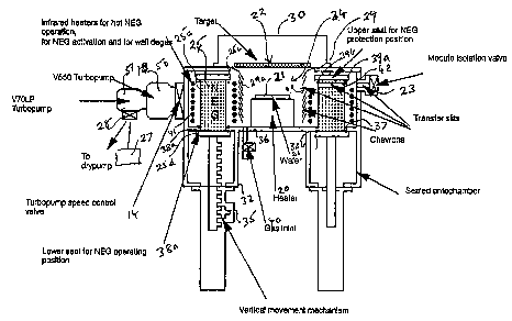
drawings, in which the single figure is a diagrammatic cross
section of a vacuum tool for carrying out reactive physical
vapor deposition.
The vacuum tool contains a wafer 21 located on a
support 20, which serves as a backside heater, in deposition
chamber 34. Target 22, which is made of titanium or
tantalum, is mounted over the wafer 21 in the deposition
chamber. The target serves as the cathode in the reactive
PVD process, and the wafer serves as the anode.
A removable cap 30 is located over the target 22 to
allow the chamber 34 to be opened for access, for example,
to permit the target 22 to be removed.
A tandem arrangement of turbomolecular pumps 50, 51
connected through valve 28 to dry pump serves to create the
initial vacuum of about 10-5 Torr prior to introduction of
the NEG pump 25. Pump 50 is a V550 turbopump and pump 51 is
a V70~P turbopump.
The donut or ring-shaped NEG pump 25 normally surrounds
the wafer 21 and support 20, providing a wafer heater. It is
mounted on a ratchet mechanism 31 extending into a sealed
cylindrical antechamber 32 below main deposition chamber 34.
The ratchet mechanism includes a pawl 35, which allows the
- 3 -

CA 02208162 1997-06-19
NEG pump to be raised into the operative position shown and
withdrawn into a retracted position within the antechamber
32. The pawl 35 can be turned by hand or by a small electric
motor. Alternatively, any suitable raising and lowering
means can be employed.
The bottom wall 36 of the deposition chamber 34 has a
circular aperture 37 accommodating the ring-shaped getter
pump 25. The ring-shaped pump 35 has a slightly recessed
body portion 25a so as to form an upper lip 25c and a lower
lip 25d.
Pairs of O-rings 38a, 38b, and 39a, 39b are provided on
the respective outer and inner surfaces of the NEG pump 25
respectively above the lower and below the upper lips 25d,
25c.
In the raised position shown the O-rings 38a, 38b seal
against lower surface of the bottom wall of the chamber 34.
In the retracted position (not shown) the O-rings 39a, 39b
seal against the upper surface of the bottom wall of the
chamber 34.
The protection shield 29 includes a plurality of baffle
plates 29a extending to the bottom wall 36 so as to
completely shield the wafer 21 and support 20. A slit 40 is
formed in the baffle plates 29a and a slit 41 is formed in
the NEG pump 25 to allow the wafers to pass therethrough en
route to the isolation valve 23 (and vice versa).
The bottom wall 36 also includes a gas inlet valve 40
for the continual admission of argon and nitrogen to the
deposition chamber 34 during reactive physical vapor
deposition. The total pressure of nitrogen can be easily
controlled by controlling the flow rate through the valve 40
and the pumping speed of the pumps 50, 57. Generally the
partial pressure of nitrogen should be in the range 0.5 to
-- 4 --

CA 02208162 1997-06-19
lOmTorr, typically 3mTorr, and the partial pressure of argon
should be in the range 0.5 to 5mTorr, typically 3mTorr.
The ring-shaped getter pump 25 is surrounded by a stack
of infrared lamps 41 for heating the getter material 25 for
the purpose of activation or regeneration. Infrared lamps
are preferred to the constantin support described with
reference to the previous embodiment.
In normal operation, the NEG pump 25 is in the raised
position shown. The infrared lamps 41 are operated for the
purpose of activating or regenerating the NEG material 25.
They can also be used to heat the NEG material during wafer
processing because the pumping speed increases significantly
with temperature. It is desirable to operate the NEG pump 25
at a temperature of about 280~C.
When it is desired to open the deposition chamber 34,
for example, to replace the target 22, the NEG pump is
withdrawn into the antechamber 33 and sealed with the aid of
seals 38a, 38b. A vacuum is maintained in antechamber 33,
which is temporarily in communication with the main
deposition chamber 34 in the intermediate positions of the
NEG pump 25. The NEG material is thus not exposed to the
atmosphere while the deposition chamber 34 is open.
The infrared lamps 41 can also serve the dual purpose
of baking the walls of the deposition chamber to drive off
absorbed gases for regeneration purposes.
The NEG pump 25 is made from a sintered mass of NEG
material shaped in an array of 240 (25cm x 5 cm) fins
distributed over a cylinder 25 cms high and having an
outside diameter of 45 cms with a total surface area of
60,000 cm2.

CA 02208162 1997-06-19
The infrared lamps are used to activate the NEG pump at
450~C for 45 minutes at 10-5 Torr and hold the NEG pump at
200~C for normal operation.
The V550/V70LP tandem turbopump configuration can be
used to prevent gas backstreaming from the drypump and
maintain a partial pressure lower than about 10-1~ Torr for
contaminants, such as H2, H20, and ~2-
In accordance with the invention, the NEG pump is madefrom an alloy consisting essentially of an alloy of
zirconium and iron, preferably consisting of 15 to 30% by
weight of Fe and from 70 to 85~ by weight Zr. A suitable
alloy is sold by SAES getters S.p.A. of Milan, Italy under
the trade designation StlO1 Getter Alloy. Such an alloy is
described in the above-referenced US patent no. 5,238,469.
The invention brings about a revolutionary advance in
the field of PDV processing. The copending application
referred to above is an extremely important advance because
it allows the elimination of the bulky and expensive
turbomolecular pumps and cryopumps that had previously been
associated with cluster tools. However, it was not
contemplated that the invention would be applicable to
reactive PVD because NEG getters generally absorb gases,
such as nitrogen, that are able to take part in a reaction.
The realization that NEG getters are available that are
insensitive to nitrogen is extremely important because it
allows reactive PVD to be carried out in the same way, i.e.
without the need for large cryopumps and the like. The
formation of titanium and tantalum nitride layers is an
extremely important as aspect of semiconductor wafer
fabrication, and the ability to extend to former invention
to such processes is very important.
It should be obvious that the above described
embodiments are merely illustrative of the application and

CA 02208162 1997-06-19
of the principles of the present invention, and numerous
modifications thereof may be devised by those skilled in the
art without departing from the spirit and scope of the
invention.

Representative Drawing
A single figure which represents the drawing illustrating the invention.
Administrative Status

2024-08-01:As part of the Next Generation Patents (NGP) transition, the Canadian Patents Database (CPD) now contains a more detailed Event History, which replicates the Event Log of our new back-office solution.

Please note that "Inactive:" events refers to events no longer in use in our new back-office solution.

For a clearer understanding of the status of the application/patent presented on this page, the site Disclaimer , as well as the definitions for Patent , Event History , Maintenance Fee  and Payment History  should be consulted.

Event History

Description Date
Inactive: IPC from MCD 2006-03-12
Time Limit for Reversal Expired 2003-06-19
Letter Sent 2002-06-19
Letter Sent 2002-04-23
Grant by Issuance 2000-08-22
Inactive: Cover page published 2000-08-21
Pre-grant 2000-05-24
Inactive: Final fee received 2000-05-24
Notice of Allowance is Issued 2000-03-13
4 2000-03-13
Letter Sent 2000-03-13
Inactive: Approved for allowance (AFA) 2000-02-24
Letter Sent 1998-03-24
Application Published (Open to Public Inspection) 1997-12-20
Request for Examination Requirements Determined Compliant 1997-11-04
All Requirements for Examination Determined Compliant 1997-11-04
Request for Examination Received 1997-11-04
Inactive: IPC assigned 1997-10-08
Classification Modified 1997-10-08
Inactive: First IPC assigned 1997-10-08
Letter Sent 1997-08-27
Inactive: Filing certificate - No RFE (English) 1997-08-27
Application Received - Regular National 1997-08-26

Abandonment History

There is no abandonment history.

Maintenance Fee

The last payment was received on 2000-04-07

Note : If the full payment has not been received on or before the date indicated, a further fee may be required which may be one of the following

  • the reinstatement fee;
  • the late payment fee; or
  • additional fee to reverse deemed expiry.

Patent fees are adjusted on the 1st of January every year. The amounts above are the current amounts if received by December 31 of the current year.
Please refer to the CIPO Patent Fees web page to see all current fee amounts.

Fee History

Fee Type Anniversary Year Due Date Paid Date
Application fee - standard 1997-06-19
Registration of a document 1997-06-19
Request for examination - standard 1997-11-04
MF (application, 2nd anniv.) - standard 02 1999-06-21 1999-05-06
MF (application, 3rd anniv.) - standard 03 2000-06-19 2000-04-07
Final fee - standard 2000-05-24
MF (patent, 4th anniv.) - standard 2001-06-19 2001-05-16
Registration of a document 2002-02-22
Owners on Record

Note: Records showing the ownership history in alphabetical order.

Current Owners on Record
ZARLINK SEMICONDUCTOR INC.
Past Owners on Record
LUC OUELLET
Past Owners that do not appear in the "Owners on Record" listing will appear in other documentation within the application.
Documents

To view selected files, please enter reCAPTCHA code :


To view images, click a link in the Document Description column (Temporarily unavailable). To download the documents, select one or more checkboxes in the first column and then click the "Download Selected in PDF format (Zip Archive)" or the "Download Selected as Single PDF" button.

List of published and non-published patent-specific documents on the CPD .

If you have any difficulty accessing content, you can call the Client Service Centre at 1-866-997-1936 or send them an e-mail at CIPO Client Service Centre.


Document
Description 
Date
(yyyy-mm-dd) 
Number of pages   Size of Image (KB) 
Abstract 1997-06-18 1 19
Description 1997-06-18 7 270
Cover Page 1999-02-25 1 41
Cover Page 1999-04-11 1 55
Cover Page 2000-08-14 1 58
Representative drawing 2000-08-14 1 18
Claims 1997-06-18 2 52
Drawings 1997-06-18 1 29
Representative drawing 1999-02-25 1 14
Courtesy - Certificate of registration (related document(s)) 1997-08-26 1 118
Filing Certificate (English) 1997-08-26 1 165
Acknowledgement of Request for Examination 1998-03-23 1 179
Reminder of maintenance fee due 1999-02-21 1 110
Commissioner's Notice - Application Found Allowable 2000-03-12 1 164
Maintenance Fee Notice 2002-07-16 1 177
Correspondence 2000-05-23 1 31