Note: Descriptions are shown in the official language in which they were submitted.
' CA 02208293 1997-06-19
P 1 5693 .S02
ROLL
CROSS-REFERENCE TO RELATED APPLICATION
The present application claims the priority under 35 U.S.C. 119 of German Patent
Application No. 196 24 737.3, filed on June 21, 1996, the disclosure of which is inco-~o~led by
5 reference herein in its entirety.
BACKGROUND OF THE INVENTION
1. FieldofInvention
The present invention relates to a roll that includes a roll tube provided with an outer
elastic coating. The sealed interior space may include a vaporizable liquid and a heat exchanger
10 for cooling heat generated in the roll during use. The sealed interior space may form a closed
system in which the heat in the roll tube may vaporize the vaporizable liquid and the heat
exchanger may be set to condense the vaporized liquid.
2. Discussion of Background Information
Rolls of the type generally described above may be utili7e-1, e.g., in super~lentl~ or soft
15 calenders. Due to the elasticity of their surfaces, these rolls are often also referred to in the art
as "soft" rolls. In use, the soft rolls and so-called hard rolls are positioned together form a nip
though which, e.g., a material web is contl~ctecl to smooth the surface of the web by applying
pressure and, if necessary, at an elevated tel~p~lalule.
During operation, the surface of the soft roll heats up due to, e.g., the flexing work
20 performed by the elastic coating. The resulting high temperature endangers the elastic coating
which drastically reduces the roll's protection against destruction.
When a roll tube is utilized as a roll jacket, e.g., in a deflection adjustment roll or
deflection compen~ting roll, the roll jacket is supported by a hydrostatic or hydrodynamic
supporting elements. In this manner, heat can be ~ sir~te~l by providing hydraulic oil in an
25 interior space of the roll. This method for stabilizing the roll telllpe.~ e, which occurs like a
secondary phenomenon with deflection adjustment rolls, however, is relatively costly.
Further, it is known to provide peripheral bores in the roll jacket of "hard" rolls so as to
enable a through flow of a heat carrier or coolant, e.g., through peripheral channels extenciing
through the peripheral bores. The heat absorption or emission of this medium, however, must
30 be m~int~ined within relatively close limits so as to prevent an irregular temperature distribution
CA 02208293 1997-06-19
P15693.S02
across the width of the roll. In a cooling process, as coolant flows through the peripheral
channels, the temperature of the coolant may generally only be allowed a maximum rise of 1 ~C,
and never more than 2~C. Thus, this cooling process requires an adequate volume of coolant.
There is also a possibility of cooling the rolls from the outside, e.g., by blowing with cool
5 air or spraying with cooling liquid. However, these possibilities for cooling the rolls are
somewhat limited. In particular, when spraying with a cooling liquid, there is a risk that the
cooling liquid may also contact the web being processed, which may adversely affect the
intçncled fini~hing of the web.
SUMMARY OF THE INVENTION
Accordingly, a particular feature of the present invention may be directed to cooling a soft
roll in a simpler manner than that disclosed in the prior art.
To achieve this above-noted feature, a roll may include a roll tube that has an elastic
coating provided on an outside of the roll tube. The roll tube may include a sealed interior space
within which a vaForizable liquid and a heat e~sh~n~er may be positioned.
In operation, the roll and roll tube may rotate. As a result of centrifugal force generated
by the rotation of the roll, the liquid provided ~vithin the interior space may be pressed against
an inside wall of the roll tube to form a liquid film. For practical purposes, an adequate volume
of liquid should be provided in the interior space so that a closed film may form that has a
thickness of, e.g., several millimP~r~. Further, heat may be transmitted to the liquid, e.g., from
20 the outside of the roll, i.e., through the roll tube. The 1~ i l led heat may vaporize the liquid
to produce steam. The vaporized liquid or steam may contact a heat exchanger so as to withdraw
or emit the heat from within the interior space. The steam may then condense or precipitate on
the heat exchanger. The con~len.~tion, through the centrifugal force, may be forced toward the
wall of the interior space, i.e., the inside surface of the roll tube. Thus, the cooling cycle may
25 start over again.
The present invention produces an intensive cooling of the roll tube through relatively
simple measures. For example, as the liquid film located on the inside of the roll tube develops
evenly, i.e., as a result of the centrifugal force, a similar even heat dissipation may also be
produced. Thus, an even tell-peldl~re can be m~int~ined with good feed across the axial length
30 and circumference of the roll tube.
CA 02208293 1997-06-19
P 1 5693 .S02
In a plefelled embodiment, the temperature of the heat exchanger may be reduced to a
temperature below the condensation temperature of the liquid. As a result, the steam may not
only be condensed or precipitated on the heat exchanger, but the condensation may also be
additionally cooled. Thus, this embodiment may produce an even greater temperature difference
5 between the roll tube and the heat exchanger. Thus, because the heat exchanger may ~ sir~te
a large volume of heat, improved heat ~ ip~tion may be achieved through the present invention.
In another preferred embodiment, the interior space may be gas-tight so that no coolant
may be lost. Further, the present invention may utilize water as the coolant. Alternatively, other
liquids, e.g., those exhibiting a low boiling point, may be utilized as the coolant for the present
10 invention. Accordingly, the ordinarily skilled artisan may set certain tenl~ re limits within
which the roll tube may be heated by selecting an a~propl;ate coolant liquid, i.e., according to
its boiling point.
In another embodiment of the present invention, the roll may be provided with journal
bearings. Further, the interior space of the roll tube may be closed off or defined at the axial
15 extremes of the roll tube by respective journals and associated compollents or walls. This
arrangement may produce a gas-tight interior space. While typical journal bearing rolls of the
prior art are generally char~cteri7P~l by a very low dead weight that results in a desired steep
characteristic curve in the calender, by ~tili7ing an additional heat exchanger in accordance with
the present invention, the roll may be cooled by simple coolants. Thus, flexing work performed
20 in the elastic coating may have no negative effects with respect to the roll telllpe.dLule and,
therefore, reduce the danger of ~l~m~ging the coating.
In accordance with the present invention, the heat exchanger may jointly rotate with the
roll tube. This embodiment may f~cilit~te the sealing of the heat exchanger against the roll tube.
That is, if the heat exchanger is jointly mounted with the roll tube, the interior space may be
25 m~int~ined stationary so that none of the gaps between the colllponents have to be sealed.
Further, the rotating heat exchanger may produce a better distribution of the liquid that is
precipitated on the heat exchanger. Drops of liquid formed from the steam, i.e., which have
precipitated at the heat exch~nger, may be centrifuged against the wall of the roll tube where they
can be revaporized. Thus, this feature of the present invention may act as a kind of pump within
30 the coolant cycle.
CA 02208293 1997-06-19
P15693.S02
In another preferred embodiment of the present invention, a flow of coolant may be fed
to the heat exchanger. The application of coolant may be a relatively simple method for
dissipating heat from the interior space of the roll tube. It may also be possible to use electrical
components having negative temperature coefficients. However, the expenditure for dissipating
volumes of heat may be relatively high. The coolant may be heated relatively fast in the heat
exchanger. However, in contrast to the prior art, the present invention is not limited to allowing
heating by only 1~C or 2~C. Further, the cooling liquid may increase by 10~C, 20~C or to an
even higher temperature. As the l~lllpeldlule of the cooling liquid increases, a colle~l~olldingly
lower flow volume of cooling liquid through the heat exchanger may be required for dissipating
the same volume of heat. Thus, in accordance with this particular embodiment of the present
invention, there may be substantially no risk of an uneven temperature distribution developing
in the roll tube.
At least one of the journals of the roll tube may be provided with a rotary feeding device,
which may be any conventional type rotary feeding device. As this arrangement requires
conveyance or flow of liquids, the difficulty ~sociated with sealing this arrangement may be less
complicated than when a conveyance of gas is utilized. The rotary feeding device may be
arranged at a side or an end of the heat exchanger which is not connected to nor within the
interior space. In this manner, the present invention does not risk allowing gas or steam to
escape from the interior space through the rotary feeding device.
The heat exchanger may be formed, e.g., as a helical tube which may enable the heat
exchanger to extend over a certain area along the axis of the roll tube. The surface available for
the heat exchange, i.e., between the coolant fed through the heat exchange tube and the steam
contained within the interior space may be enlarged by a simple method.
Further, an eV~cll~ting device may be provided in the interior space to reduce the pressure
within the interior space. Consequently, the release of plcs~ e correspondingly reduces the
boiling t~ e,dlu~e of the liquid contained in the interior space. Thus, the pressure may be
adjusted to influence the temperature of the roll tube. For example, as the boiling telllpeldL lre
of the liquid is lowered, the faster the liquid evaporates. Since the largest volume of heat may
be "consumed" during evaporation, the temperature of the roll tube may be located with good
feed in the vicinity of the liquid boiling point in the interior space.
- 4 -
CA 02208293 1997-06-19
. ~
P15693.S02
The elastic coating may be made of, e.g., plastic. Further, epoxy resins may also be
considered as applopliate synthetic materials, and plastic coatings have been developed that
exhibit a high degree of elasticity.
Preferably, a roll rotary drive may be provided for driving the roll tube. The roll rotary
drive may enable rotation of the roll, even when no web is being guided through the nip, or when
the nip is not yet closed. In this manner, the liquid film may form at the inside of the roll tube
prior to initiating the actual calendering operation, so that the cooling may start immediately.
The present invention may be directed to a roll that may include a roll tube having an
outside surface and a sealed interior space, and an elastic coating provided on the outside surface.
The roll may also include a vaporizable liquid and a heat exchanger that may be positioned
within the sealed interior space.
According to another feature ofthe present invention, a te~ )el~ e ofthe heat exch~nger
may be set to a te~llperalu~ below a conflen~tion telllpel~ e of a vaporized portion of the
vaporizable liquid.
According to another feature of the present invention, the sealed interior space may be
gas-tight.
According to still another feature of the present invention, the roll may also include
journal bearings, journals, and walls. At least one of the journals and the walls may close axial
extremities of the interior space.
According to a further feature of the present invention, the heat exch~nger may jointly
rotate with the roll tube.
According to another feature of the present invention, the heat exchanger may include a
coolant supplied from outside of the roll tube. Further, a rotary feeding device may be associated
with at least one journal to supply the coolant.
According to a still further feature of the present invention, the heat exchanger may
include a helical tube.
According to yet another feature of the present invention, the roll may also include an
evacl.~ting device coupled to the interior space.
According to another feature of the present invention, the elastic coating may include
plastic.
- 5 -
CA 02208293 1997-06-19
.
P 1 5693 .S02
According to still another feature of the present invention, the roll may also include a roll
rotary drive.
The present invention may also be directed to a calender roll that may include a roll tube
including a gas-tight section and the gas-tight section including a vaporizable liquid and a heat
5 exchanger.
According to another feature of the present invention, the vaporizable liquid may be
adapted to form a film over an interior wall of the gas-tight section.
According to another feature ofthe present invention, the heat exchanger may be adapted
to receive condensed vaporized liquid.
10According to a further feature ofthe present invention, the roll may include a journal and
the heat exchanger may extend through the journal. Further, the journal may include a static seal
and the heat exchanger may extend through the static seal.
According to still another feature of the present invention, the gas-tight section may form
a closed system in which vaporizing the vaporizable liquid cools the roll tube and the heat
15exchanger cools the vaporized liquid.
According to another feature of the present invention, the roll may include a drive motor
for rotating the roll tube and the heat exch~n~er may be coupled to rotate with the roll tube.
According to a still further feature of the present invention, the roll may include a
pressure valve to adjustably vary the plt;S:jUl'e within the gas-tight section.
20According to another feature of the present invention, the heat exchanger may include a
circulating coolant. Further, the coolant may include one of water, alcohols and hydrocarbons.
The present invention may be directed to a method for cooling a roll having an elastic
coating in use in a calender. The method may include forming a vaporizable liquid film on an
interior surface of the roll, vaporizing the vaporizable liquid film to produce vaporized liquid,
25con-l~n~ing the vaporized liquid to produce a con.l~mecl liquid, and forcing the con~l~n~ecl liquid
onto the interior surface of the roll.
According to another feature of the present invention, the forming of the vaporizable
liquid film may include rotating the roll.
According to still another feature of the present invention, the vaporizing of the
30vaporizable liquid film may include frictionally heating the interior surface to a temperature at
CA 02208293 1997-06-19
P15693.S02
least equal to a boiling point te~ ,eldlllre of the vaporizable liquid. Further, the frictional heating
of the interior surface may include forming a nip between the roll and an opposing roll and
rotating the roll and the opposing roll. Alternatively, the frictional heating of the interior surface
may include milling the elastic coating.
According to a still further feature of the present invention, the condensing of the
vaporized liquid may include positioning a heat exchanger within the roll and circulating a
coolant having a lelll~cldlule less than or equal to the con(l~n~tion point of the vaporized liquid
through the heat exchanger.
According to another feature of the present invention, the method may also include
providing a gas-tight seal to enclose the vaporizable liquid within the roll, positioning a heat
exchanger within the roll, and circulating a coolant through a heat exchanger to condense the
vaporized liquid. Further, the method may include rotating the heat exchanger to remove the
condensed vaporized liquid.
According to still another feature of the present invention, the method may also include
supplying the coolant from outside of the roll.
According to yet another feature of the present invention, the forcing of the condensed
liquid may include positioning a heat ~ch~nger within the roll and rotating the heat exchanger.
Other exemplary embo-lim~nt~ and advantages of the present invention may be
ascertained by reviewing the present disclosure and the accolllpallyillg drawing figures.
BRIEF DESCRIPTION OF DRAWING
The present invention may be further described in the detailed description which follows,
with reference to the noted drawing by way of a non-limiting example of a preferred embodiment
of the present invention and wherein:
The Figure illustrates a schPm~tic cross-section of the calender roll in accordance with
the present invention.
DETAILED DESCRIPTION OF THE PREFERRED EMBODIMENT
The particulars shown herein are by way of example and for purposes of illustrative
discussion of the pl~felled embo~iment~ of the present invention only and are presented in the
cause of providing what is believed to be the most useful and readily understood description of
the principles and conceptual aspects ofthe invention. In this regard, no attempt is made to show
- 7 -
CA 02208293 1997-06-19
P l 5693.S02
structural details of the invention in more detail than is necessary for the fundamental
underst~n~ling of the invention, the description taken with the drawing figure making appalc~ll
to those skilled in the art how the invention may be embodied in practice.
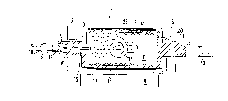
A roll 1 may be provided with a roll tube 2 which may be arranged via journals 3 and 4
5 within bearings 5 and 6 in a calender (not shown in detail). If necessary, bearings 5 and 6 may
be raised or lowered in the vertical direction and/or adjusted horizontally so as to selectively open
or close a nip 7 with respect to an opposing roll 8.
Journals 3 and 4 may extend from a roll-end e~llcll~iLy, i.e., components or walls 9 and
10, along a central axis of roll tube 2. Roll tube 2, journals 3 and 4, and walls 9 and 10 may
10 enclose and surround an interior space 11 to provide a sealed space.
Sealed interior space 11 may be provided with or contain a predetennined volume of
vaporizable liquid 12, e.g., water. The volume of liquid provided should be sufficient, so that
during operation, i.e., when the roll is rotating, a liquid film thickness of, e.g., several millimeters
may be formed at or along an inside wall 13 of roll tube 2, e.g., by centrifugal force. In the
15 Figure, a vaporizable liquid film of vaporizable liquid 12 is s~hPm~tically illustrated at an upper
inside wall and at a lower inside wall of roll tube 2. Clearly, the illu~lla~d wave shaped surface
is for the purposes of illustration and explanation of the liquid film layer, and the application
should not be construed as limited to an lm-lnl~ting or sinuous film surface along inside wall 13.
A heat exchanger 14 may extend into interior space 11, and may be formed, e.g., as a
20 helical tube, as shown in the exemplary drawing. Heat exchanger 14 may axially extend into
interior space 11 via a certain path.
Heat exchanger 14 may be provided with connections 15 and 16 which may be con~ cte~l
through journal 4. At journal 4, a static seal 17 may be positioned to ensure a gas-tight seal of
interior space 11 , through which connections 1 5 and 1 6 may extend without compromising the
25 sealed nature of interior space 11. Additionally, journal 4 may be positioned, e.g., at the non-
drive side or operator side, of roll 1.
Connections 15 and 16 may be utilized to supply and evacuate coolant, e.g., as indicated
by arrows 18, through a known rotary feeding device l9. In general, a rotary feeding device
requires that components movable in opposition must be sealed, however, in accordance with the
30 present invention, this requirement is not critical. That is, because there is no physical
- 8 -
CA 02208293 1997-06-19
Pl5693.S02
connection between rotary feeding device 19 and interior space l l, there is no danger that the
gas-tight seal of the interior space 11 will be compromised by the use of rotary feeding device
l9. Accordingly, rotary feeding device 19 allows the admission of coolant liquids or gases only
to the interior of heat exchanger 14 through connections 15 and 16, not to interior space 11. The
5 coolant flowing through heat exchanger 14 may be, e.g., water.
Further, interior space 11 may be coupled via an evacuating valve 20 with an evacuating
connection 21. Evacuating connection 21 may, e.g., be coupled to a vacuum pump and, if
necessary, to a m~nll~lly operated vacuum pump. Accordingly, when evacuating valve 20 is
opened, the pressure within interior space 11 may be reduced. This reduction in internal
0 pl~s~ule, therefore, colle~olldingly reduces the boiling point ~l~l~e.dlure of liquid 12 contained
within interior space. In this manner, the boiling point temperature of the liquid utilized within
interior space 11 may be varied in accordance with desired operating parameters.An elastic coating 22, formed of a synthetic m~teri~l, e.g., epoxy resin, may be provided
around an outside of roll tube 2. During operation of roll 1, i.e., when rolls 1 and 8 interact to
15 treat the web guided through the formed nip, coating 22 may be milled. The milling of coating
22 may produce heat that may increase both the lellll)eldlure of coating 22 and the temperature
of roll tube 2.
Further, as roll 1 rotates, a centrifugal force is created or results within roll 1 to form a
closed liquid film along inside wall 13 of roll tube 2. Liquid 12 clinging to or forced against
20 inside wall 13 of roll tube may be heated and vaporized as soon as boiling tell~.dlure is attained
due to the heat generated, e.g., by the operation of roll 1. The boiling telllpc~dlule may be
selectably set by the user by at least one of selecting a suitable liquid 12 and selecting a suitable
pressure for interior space 11.
When liquid 12 vaporizes, the vaporization draws heat from roll tube 2 to fill interior
25 space 11 with steam of the liquid 12. The steam may precipitate or condense at heat exchanger
14 due to the flow of coolant through heat çx~nger 14. Further, heat exchanger 14 may jointly
rotate with roll tube 2. That is, the precipitates or con.lçnced liquid on heat exchanger 14 may
be centrifuged toward and onto inside wall 13 due to the rotation of heat exchanger 14. As the
precipitate liquid is forced onto inside wall 13, the liquid may be revaporized by the increasing
30 temperature of roll tube 2 and, thus, restart the cooling process.
CA 02208293 1997-06-19
P15693.S02
Because the coolant in heat exchanger 14 is circulated by rotary feeding device 18, and
because the coolant flowing through heat exchanger 14 does not contact a surface of roll l, the
liquid telllpeldlulc does not need to be constrained within narrow limits to ensure even cooling
of roll tube 2, as is necessary in the prior art. That is, because the roll tube is cooled by the
5 vaporization of the liquid film along inside wall 13 within interior space 1 1, the coolant in heat
exchanger 14 may be allowed to heat considerably, e.g., by 10~C, 20~C or more. Further, the
lclll~eldlulc of the coolant in heat exchanger 14 may increase as long as the steam or vaporized
liquid 12 continues to precipitate or condense on heat exchanger 14 in amounts sufficient to
m~int~in the desired liquid film thickness along inside wall 13. Because the present invention
10 allows the coolant within the heat exc~ nger to be heated to a certain extent, the volume flow of
coolant through heat exchanger 14 can be kept low. Accordingly, only a small volume of coolant
needs to be conducted through rotary feeding device 19, thus, facilitating the sealing of rotary
feeding device 19.
Interior space 11 may be sealed gas-tight to produce a closed cycle of vaporization and
con~çn~tion, i.e., from inside wall 13 of roll tube 2 to heat exchanger 14 to inside wall 13.
Further, it is noted that liquids other than water, e.g., alcohols or other hydrocarbons, may be
utili~d as liquid 12.
Further, a drive 23 may be provided to exert a rotational force on roll 1. Drive 23 may
be positioned to drive roll 1 at journal 3. Further, rotation of roll 1 may occur before nip 7 is
20 closed. In this manner, the cooling of roll 1 may begin prior to operation of the system. It is
noted that, as long as liquid 12 is not vaporized within roll tube 2, the tell~cldlllre of the coolant
flowing through heat exchanger 14 will not increase. Thus, no heat exchange occurs and no
excessive cooling of roll tube 2 and the coating 22 occurs.
It is noted that the foregoing examples have been provided merely for the purpose of
25 explanation and are in no way to be construed as limiting of the present invention. While the
invention has been described with reference to a preferred embodiment, it is understood that the
words which have been used herein are words of description and illustration, rather than words
of limitation. Changes may be made, within the purview of the appended claims, as presently
stated and as amended, without departing from the scope and spirit of the invention in its aspects.
30 Although the invention has been described herein with reference to particular means, materials
- 10-
CA 02208293 1997-06-19
P15693.S02
and embodiments, the invention is not intended to be limited to the particulars disclosed herein;
rather, the invention extends to all functionally equivalent structures, methods and uses, such as
are within the scope of the appended claims.
- 11 -