Language selection

Search

Patent 2208379 Summary

Third-party information liability

Some of the information on this Web page has been provided by external sources. The Government of Canada is not responsible for the accuracy, reliability or currency of the information supplied by external sources. Users wishing to rely upon this information should consult directly with the source of the information. Content provided by external sources is not subject to official languages, privacy and accessibility requirements.

Claims and Abstract availability

Any discrepancies in the text and image of the Claims and Abstract are due to differing posting times. Text of the Claims and Abstract are posted:

  • At the time the application is open to public inspection;
  • At the time of issue of the patent (grant).
(12) Patent Application: (11) CA 2208379
(54) English Title: SUPPORT POST FOR A BICYCLE SEAT
(54) French Title: TIGE D'APPUI POUR SELLE DE BICYCLETTE
Status: Deemed Abandoned and Beyond the Period of Reinstatement - Pending Response to Notice of Disregarded Communication
Bibliographic Data
Abstracts

English Abstract


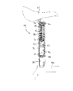
A support post for a bicycle seat includes a first
tubular member and a second tubular member. The first tubular
member has an interior cavity. The second tubular member is
telescopically received within the interior cavity of the first
tubular member. A shock absorbing medium, such as a coil
spring, resists telescopic movement of the second tubular into
the interior cavity. A bicycle seat is mounted to a remote end
of one of the first tubular member and the second tubular
member.


French Abstract

Une tige d'appui pour une selle de bicyclette comprend un premier élément tubulaire et un deuxième élément tubulaire. Le premier élément tubulaire a une cavité intérieure. Le deuxième élément tubulaire est reçu de façon télescopique dans la cavité intérieure du premier élément tubulaire. Un moyen amortisseur, tel un ressort hélicoïdal, résiste au mouvement du deuxième élément tubulaire dans la cavité intérieure. Une selle de bicyclette est montée sur le bout éloigné de l'un des premier et deuxième éléments tubulaires.

Claims

Note: Claims are shown in the official language in which they were submitted.


THE EMBODIMENTS OF THE INVENTION IN WHICH AN EXCLUSIVE PROPERTY
OR PRIVILEGE IS CLAIMED ARE DEFINED AS FOLLOWS:
1. A support post for a bicycle seat, comprising:
a first tubular member having an interior cavity;
a second tubular member telescopically received within the
interior cavity of the first tubular member;
shock absorbing means to resist telescopic movement of the
second tubular member into the interior cavity; and
means for mounting a bicycle seat to a remote end of one
of the first tubular member and the second tubular member.
2. The support post as defined in Claim 1, wherein the shock
absorbing means is a coil spring.
3. The support post as defined in Claim 1, wherein the shock
absorbing means is hydraulic fluid.

4. In combination:
a bicycle frame;
a support post for a bicycle seat mounted in a
substantially vertical orientation to the bicycle frame, the
support post comprising:
a first tubular member having an interior cavity;
a second tubular member telescopically received
within the interior cavity of the first tubular member;
shock absorbing means to resist telescopic movement
of the second tubular member into the interior cavity;
mounting means for mounting a bicycle seat to a
remote end of one of the first tubular member and the second
tubular member; and
a bicycle seat mounted on the mounting means.

Description

Note: Descriptions are shown in the official language in which they were submitted.


CA 02208379 1997-06-20
TITLE OF THE lNV~L~lON:
support post for a bicycle seat
NAME OF lNV~NlOR:
Bayne Jason Andronyk
FIELD OF THE lNV~.llON
The present invention relates to a support post for a
bicycle seat
BACKGROUND OF THE lNV~NllON
A bicycle seat is mounted on a support post which is
telescopically received in a receptacle in a bicycle frame.
The support post can be secured in a variety of telescopic
positions relative to the frame, in order to adjust a height
of the bicycle seat to accommodate a leg length of a rider.
When a bicycle is ridden over rough terrain, it is
subjected to jarring impacts. That portion of each jarring
impact that is not absorbed by the bicycle's tires, is
transmitted along the support post to the bicycle seat and then
to the spine of the rider. The bicycle seat has limited
padding and, therefore, provides only limited relief from such
jarring impacts.
SUMMARY OF THE lNV~NllON
What is required is a support post for a bicycle seat that
will reduce the intensity of jarring impacts transmitted along

CA 02208379 1997-06-20
the support post to the bicycle seat.
According to one aspect of the present invention there is
provided a support post for a bicycle seat which includes a
first tubular member and a second tubular member. The first
tubular member has an interior cavity. The second tubular
member is telescopically received within the interior cavity
of the first tubular member. Shock absorbing means resists
telescopic movement of the second tubular into the interior
cavity. Mounting means is provided for mounting a bicycle seat
to a remote end of one of the first tubular member and the
second tubular member.
The support post, described above, is built to absorb
shocks. Jarring impacts result in a telescopic movement of the
second tubular member into the interior cavity of the first
tubular member, instead of being transmitted to the bicycle
seat. The telescopic movement is cushioned by the shock
absorbing means positioned within the interior cavity. The
shock absorbing means can take a variety of forms, including
a coil spring, hydraulic fluid or both.
BRIEF DESCRIPTION OF THE DRAWINGS
These and other features of the invention will become more
apparent from the following description in which reference is
made to the appended drawings, wherein:
FIGURE 1 is a side elevation view, partially in section,
of a first embodiment of support post for a bicycle seat
constructed in accordance with the teachings of the present
invention.
DETAILED DESCRIPTION OF THE PREFERRED EMBODIMENT
The preferred embodiment, a support post for a bicycle

CA 02208379 l997-06-20
seat generally identified by reference numeral 10, will now be
described with reference to FIGURE 1.
Referring to FIGURE 1, support post 10 includes a first
tubular member 12 and a second tubular member 14. First
tubular member 12 has a first end 16, a second end 18 and an
interior cavity 20. Second tubular member 14 has a first end
22 and a second end 24. Second end 24 of second tubular member
14 iS telescopically received within interior cavity 20 at
10 first end 16 of first tubular member 12. Shock absorbing
means, which will hereinafter be further described, are
provided to resist telescopic movement of second tubular member
14 into interior cavity 20 of first tubular member 12. The
shock absorbing means can be in the form of a spring, hydraulic
15 fluid or both. In the illustrated embodiment both are
employed. A coil spring 26 iS positioned between retaining
plates 28 and 30. Retaining plate 28 iS secured to first
tubular member 12. Retaining plate is secured to second
tubular member 14. Spring 26 resists telescopic movement of
20 second tubular 14 into interior cavity 20. In addition,
interior cavity 20 iS filled with hydraulic fluid 32, which
further resists movement. A bicycle seat 34 iS mounted to first
end 22 of second tubular member 14, and secured in position by
a seat post clamp 36. Second end 18 of first tubular member
25 12 iS secured within a receptacle 38 of a bicycle frame 40.
In operation, jarring impacts result in telescopic
movement of second tubular member 14 into interior cavity 20
of first tubular member 12. This telescopic movement is
absorbed by coil spring 26 and hydraulic fluid 32.
It will be apparent to one skilled in the art that
modifications may be made to the illustrated embodiment without
departing from the spirit and scope of the invention as
hereinafter defined in the Claims.

Representative Drawing
A single figure which represents the drawing illustrating the invention.
Administrative Status

2024-08-01:As part of the Next Generation Patents (NGP) transition, the Canadian Patents Database (CPD) now contains a more detailed Event History, which replicates the Event Log of our new back-office solution.

Please note that "Inactive:" events refers to events no longer in use in our new back-office solution.

For a clearer understanding of the status of the application/patent presented on this page, the site Disclaimer , as well as the definitions for Patent , Event History , Maintenance Fee  and Payment History  should be consulted.

Event History

Description Date
Application Not Reinstated by Deadline 2000-06-20
Time Limit for Reversal Expired 2000-06-20
Deemed Abandoned - Failure to Respond to Maintenance Fee Notice 1999-06-21
Application Published (Open to Public Inspection) 1998-12-20
Inactive: IPC assigned 1997-09-11
Classification Modified 1997-09-11
Inactive: IPC assigned 1997-09-11
Inactive: First IPC assigned 1997-09-11
Inactive: Filing certificate - No RFE (English) 1997-08-29
Application Received - Regular National 1997-08-27

Abandonment History

Abandonment Date Reason Reinstatement Date
1999-06-21

Fee History

Fee Type Anniversary Year Due Date Paid Date
Application fee - small 1997-06-20
Owners on Record

Note: Records showing the ownership history in alphabetical order.

Current Owners on Record
BAYNE JASON ANDRONYK
Past Owners on Record
None
Past Owners that do not appear in the "Owners on Record" listing will appear in other documentation within the application.
Documents

To view selected files, please enter reCAPTCHA code :


To view images, click a link in the Document Description column (Temporarily unavailable). To download the documents, select one or more checkboxes in the first column and then click the "Download Selected in PDF format (Zip Archive)" or the "Download Selected as Single PDF" button.

List of published and non-published patent-specific documents on the CPD .

If you have any difficulty accessing content, you can call the Client Service Centre at 1-866-997-1936 or send them an e-mail at CIPO Client Service Centre.

({010=All Documents, 020=As Filed, 030=As Open to Public Inspection, 040=At Issuance, 050=Examination, 060=Incoming Correspondence, 070=Miscellaneous, 080=Outgoing Correspondence, 090=Payment})


Document
Description 
Date
(yyyy-mm-dd) 
Number of pages   Size of Image (KB) 
Description 1997-06-19 3 111
Abstract 1997-06-19 1 14
Claims 1997-06-19 2 35
Drawings 1997-06-19 2 35
Representative drawing 1999-01-05 1 7
Filing Certificate (English) 1997-08-28 1 164
Reminder of maintenance fee due 1999-02-22 1 111
Courtesy - Abandonment Letter (Maintenance Fee) 1999-07-18 1 186