Note: Descriptions are shown in the official language in which they were submitted.
CA 02208696 1997-06-23
1 "SLIDING BEARINGS FOR CHOCKS IN ROLLING MILL STANDS WITH
2 CROSSED DISPLACEMENT OF THE ROLLS UNDER LOAD"
3 * * * * *
4 This invention concerns sliding bearings for chocks in
rolling mill stands with crossed displacement of the rolls
6 under load as set forth in the main claim.
7 The sliding bearings are applied in cooperation with the
8 chocks of the four-high rolling mill stands to produce hot
9 rolled sheet and/or large plate which include the crossed
displacement of the rolls also during the hot rolling cycle.
11 The state of the art covers four-high rolling mill stands
12 which comprise two opposed working rolls associated with
13 relative back-up rolls with the function of limiting the
14 bending of the working rolls during the rolling step.
Moreover the state of the art also covers rolling
16 techniques which include the reciprocal pair crossing of
17 both pairs of rolls or at least the crossed displacement of
18 the working rolls alone.
19 These techniques make it possible to control more
accurately the profile of the rolled product and therefore
21 more generally to obtain products of a higher quality.
22 At the present time the pair crossing movements are
23 carried out during the resting stage between the rolling of
24 two successive slabs; this is necessary because of the
considerable thrust forces transmitted by the rolls during
26 the passage of the rolled product which make this
27 displacement practically impossible during the rolling step.
28 These thrust forces generate friction between the chocks
29 of the upper and lower back-up rolls and the respective
organs, such as millscrews, hydraulic actuator capsules,
31 spacers, etc., which discharge the rolling force onto the
32 housing of the rolling mill stand.
s 33 This friction contrasts the pair crossing movement.
CA 02208696 1997-06-23
1 The introduction of continuous rolling of sheet or large
2 plate, with welding of the ends of the individual slabs, has
3 highlighted this problem of the pair crossing of rolls,
4 which in this case must necessarily take place also during
the processing step.
6 To carry out pair crossing in rolling mill stands such as
7 those known to the state of the art is in fact extremely
8 difficult and inaccurate because of the above-mentioned
9 friction which contrasts the crossing movements; this causes
disfunctions and/or damage in the rolling assembly, it
11 causes products of an inferior quality to be obtained, wear
12 in the components which are in reciprocal contact, high
13 powers in play and a whole series of other disadvantages.
14 Various solutions have therefore been proposed to solve
the problem of moving the rolls under load with respect to
16 the relative chocks, but these solutions have not been able
17 to solve the problem efficiently.
18 JP 57-193211 teaches to use sliding bearings suitable to
19 reduce the friction between the supporting chocks of the
back-up rolls and the corresponding equalizer beams on which
21 the adjustment means of the stand act.
22 The equalizer beams make the structure of the stand
23 heavy, and also make the conventional operations of
24 adjusting the rolls and transmitting the rolling load less
precise.
26 The sliding bearings consist of a series of cylindrical
27 rollers arranged parallel to each other and separated in
28 such a manner as to cover substantially the entire width of
29 the relative chock.
This parallel arrangement of the cylindrical rollers, and
31 their cylindrical shape itself, causes a high level of
32 rubbing on the horizontal plane, both between the
33 cylindrical rollers and the chock and also between the
CA 02208696 1997-06-23
1 cylindrical rollers and the stationary housing; on the one
2 hand this makes the pair crossing adjustment very imprecise
3 and on the other hand it requires high forces of thrust to
4 be used. Moreover the cylindrical rollers are subjected to
anomalous stress, with localised and disuniform overloads.
6 GB-A-2141959 describes friction-reducing means interposed
7 between the chock and the housing and not between the chock
8 and the means to adjust the rolls.
9 The friction-reducing means can include, in the various
solutions proposed, limiting plates inside which a fluid is
11 made to circulate, a series of cylindrical rollers arranged
12 parallel to each other on the width of the relative chock
13 and a series of pads made of high resistance elastic
14 material, for example rubber or similar.
In the first case, the plates to limit the fluid cause
16 problems if the rolling stand includes systems to adjust the
17 rolls and to transmit the load placed between the housing
18 and the chock.
19 Moreover, they create problems of sliding friction and
therefore of wear caused by rubbing between the parts in
21 reciprocal movement.
22 The system with parallel cylindrical rollers has the same
23 problems as those mentioned above with regard to JP'211,
24 while the system with elastic pads does not guarantee a
sufficient reduction in the friction, given the extremely
26 high forces of thrust which act between the housing and the
27 chock when the rolls are under load.
28 JP 06-269812 does not refer to a four-high stand and
29 includes friction-reducing means between the supporting
chock of the working rolls and the stationary housing. These
31 means consist of two plates arranged in contact with each
32 other defining small chambers into which fluid under
33 pressure is fed.
CA 02208696 1997-06-23
- 1 The surface of the parts in contact is very large, and
2 this causes a minimum reduction of the friction, and
3 premature wear; moreover, a great force of thrust is
4 required due to the sliding friction which develops between
the two parts in reciprocal movement.
6 The Research Disclosure n~. 293, September 1988, simply
7 describes the introduction of lubrificating fluid into pads
8 located between the hydraulic capsules and the relative
9 chocks, but this solution does not solve any of the above-
mentioned problems.
11 JP 04-55004 describes the use of cylindrical bearings
12 consisting of a plurality of small rollers of very reduced
13 diameter arranged radially with their axis lying on the
14 radius of the circumference where the centre is the point of
rotation of the chock.
16 This solution, although it improves on the solution with
17 the cylindrical rollers arranged parallel, does not
18 completely solve the problems which derive from using small
19 cylindrical rollers which in any case cause horizontal
rubbing of the parts in reciprocal movement precisely
21 because of the cylindrical shape of the friction-reducing
22 rollers.
23 Moreover, this solution involves complex construction,
24 assembly and adjustment, and also keeps wide areas without
rollers, with a high concentration of loads, which
26 concentration is accentuated by the small size of the
27 rollers themselves.
28 Moreover, this document also proposes using an equalizer
29 plate placed between the chock and the housing.
For this reason, it does not solve the problems of
31 decreased accuracy of the crossover movements, the need to
32 use extremely high displacement forces, and the premature
~ 33 wear of the parts in reciprocal contact.
CA 02208696 1997-06-23
1 The present applicants have designed, tested and embodied
2 this invention in order to overcome the shortcomings of the
3 state of the art and to achieve a better solution than those
4 already known in terms of accuracy in positioning, wear of
the parts in reciprocal movement, and displacement force
6 required.
7 This invention is set forth and characterised in the main
8 claim, while the dependent claims describe variants of the
9 main embodiment.
The purpose of the invention is to provide sliding
11 bearings to apply in cooperation with the chocks of rolls in
12 four-high rolling mill stands for hot rolled strip or sheet
13 which will make it possible to carry out the crossed
14 displacement of the rolls during the rolling step, thus
considerably reducing, or making substantially ineffective,
16 the forces of friction which contrast this pair crossing
17 movement.
18 To be more exact, the invention substantially annuls any
19 rubbing on the horizontal plane between the parts in
reciprocal movement, and eliminates any component of sliding
21 friction, thus minimizing wear and the amount of
22 displacement force required, and ensuring maximum accuracy
23 of the crossover movements of the rolls.
24 The invention is substantially composed of an anti-
friction element located between the respective organs to
26 adjust the gap and to transmit load to the rolls
27 (millscrews, capsules, spacers, etc.) and the outer face of
28 the chock of the back-up roll to be displaced and in
29 correspondence with which chock these organs act.
According to a first embodiment of the invention, the
31 anti-friction element is composed of a hydrostatic bearing
32 inside which, before the crossing angle is varied, a desired
33 value of pressure of the circulating liquid is obtained.
CA 02208696 1997-06-23
1 The hydrostatic bearing comprises a plurality of
2 hydrostatic chambers or pockets defining a clearance between
3 the organs to regulate the gap and the outer face of the
4 relative chock, the chambers or pockets being suitable to be
filled with fluid at the desired pressure during the
6 crossing of the rolls under load.
7 Thanks to these hydrostatic chambers or pockets defining a
8 clearance between the moving parts, which clearance is
9 filled with fluid, there is no contact between the moving
parts and therefore no rubbing. In this way it is possible
11 to avoid problems of premature wear, reduced accuracy of
12 adjustment as time passes, the need for maintenance and the
13 need to increase the force required by the organs which
14 perform the crossing of the rolls.
During those processing steps when the rolls maintain a
16 stable pair crossing position, the pressure of the liquid
17 remains substantially nil, and the load is transmitted
18 ordinarily onto the relative chocks.
19 During those steps when the reciprocal crossed position of
the rolls is varied, before carrying out the displacement,
21 the pressure of the liquid is increased, thus creating in
22 fact a sliding fluid layer without contact between the chock
23 and the relative organs to regulate the gap and transmit the
24 load; this sliding fluid layer enables the rolls to be
displaced in a condition of minimum friction, minimum wear
26 on the parts and minimum displacement force required.
27 The pressure of the liquid is regulated and controlled by
28 a control unit which monitors and elaborates a series of
29 parameters relating to the processing conditions, and sends
commands to the unit which regulates the hydrostatic
31 bearing.
32 This control unit acts on the mechanical adjustment means
33 to which it transmits any necessary commands to compensate
CA 02208696 1997-06-23
1 the laminating load in the event that the laminating load is
2 influenced by the action of the liquid of the hydrostatic
3 bearing on the chock.
4 According to another embodiment of the invention, the
anti-friction element which achieves the sliding bearings
6 according to the invention is composed of at least a
7 circular sector of a conical or truncated cone roller
8 bearing located between the organs to transmit the load and
9 to regulate the gap between the rolls and the relative outer
face of the chock on which the organs act.
11 According to a variant, the rollers are barrel-shaped, and
12 their curvature is a function of the load which is applied
13 and of the elastic property of the rollers themselves.
14 According to the invention the rollers of the bearing are
located radially in such a way that the extensions of their
16 axes of rotation intersect on a vertical axis passing
17 through the mean point of the rolls which are to be
18 displaced.
19 The conical or truncated cone rollers according to the
invention have their top part, or smaller base, facing the
21 chock which is opposite the one with which they are
22 associated.
23 The radial arrangement of the rollers and their conical
24 shape minimises and even annuls the rubbing component, and
therefore the sliding friction, on the horizontal plane of
26 the chocks as they are crossed over under load.
27 Since rubbing is annulled, a plurality of advantages are
28 achieved in terms of reduced wear, maximum accuracy in
29 displacement, minimum force of displacement required,
stability in time and other advantages.
31 According to a variant of this embodiment, there are a
32 plurality of pads with circulating small cylindrical
33 rollers, the pads being substantially conical in
CA 02208696 1997-06-23
1 conformation, being located radially in a sector and having
2 the extensions of their relative axes intersecting
3 substantially in correspondence with a vertical axis passing
4 through the mean point of the rolls.
According to a further variant, the anti-friction sliding
6 means are composed of barrel rollers arranged in a sector.
7 In all the embodiments of the invention, therefore, the
8 displacement of the rolls takes place in conditions of
9 substantially no friction or horizontal rubbing between the
chocks of the rolls and the relative hydraulic compression
11 and adjustment capsules, thus allowing the manoeuvre to be
12 carried out more quickly and more accurately and
13 considerably reducing the wear between the contact surfaces
14 of the moving parts.
As the conditions in which the rolls are displaced are
16 better, so it is possible to control the profile of the
17 rolled product better, and therefore to obtain products of
18 optimum quality, exploiting moreover the advantages given by
19 the continuous rolling.
The attached figures are given as a non-restrictive
21 example and show two preferred embodiments of the invention
22 as follows:
23 Fig.1 is a three-dimensional part section view of the
24 sliding bearings according to a first embodiment of
the invention;
26 Fig.2 is a part transverse section of the rolling mill stand
27 shown in Fig.1;
28 Fig.3 is a part transverse section of a variant of the
29 bearings according to the invention;
Fig.4 is a diagram of a view from above the rolling mill
31 stand shown in Fig.3.
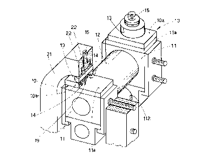
32 The number 10 in the àttached figures denotes generally
33 the sliding bearings according to the invention for the
CA 02208696 1997-06-23
1 chocks 11 of back-up rolls 12 in four-high rolling mill
2 stands which include the crossed displacement of at least
3 one pair of rolls respectively back-up rolls 12 and working
4 rolls 112.
In this case, the bearings 10 are located in an
6 intermediate position between a thin distribution plate lla,
7 whose only purpose is to distribute the load over the whole
8 width of the relative chock 11, solid at the upper part with
9 both the chocks 11 of the back-up roll 12 which is to be
displaced, and the relative hydraulic compression capsules
11 13 which act on the chocks.
12 This crossing movement is obtained by activating
13 adjustment means, referenced by the number 20, associated
14 with the outer side ~aces of the chocks 11 and solid with
the stationary housing 21.
16 In the case of Figs. 1 and 2, the sliding bearings 10 are
17 composed of a hydrostatic bearing lOa solid with the
18 hydraulic capsule 13, comprising one or more open chambers
19 or hydrostatic pockets 14 on the upper surface of the
distribution plate lla into which the pressure liquid is
21 introduced.
22 The hydrostatic chambers or pockets 14 are defined by
23 limiting walls 22.
24 The hydrostatic chambers or pockets 14 and the limiting
walls 22 define a clearance 19 which is thinner than the
26 upper face of the relative chock 11, or in this case of the
27 distribution plate lla.
28 When a condition prevails whereby the rolling rolls 12,
29 112 are maintained in a stable crossover position, the
pressure of the liquid inside the bearing lOa is maintained
31 substantially nil, and the load is transmitted by the
32 hydraulic capsule 13 by means of a direct contact between
33 the hydrostatic bearing lOa and the distribution plate lla.
CA 02208696 1997-06-23
- 10 -
- 1 Before the crossed displacement of the rolling rolls
2 12,112, the pressure of the liquid inside the hydrostatic
3 bearing lOa is increased, thus creating, in correspondence
4 with the open chambers or hydrostatic pockets 14, a layer of
liquid between the upper surface of the distribution plate
6 lla and the lower surface of the hydrostatic bearing lOa,
7 the layer of fluid completely filling the clearance 19.
8 This fluid diaphragm enables the rolling rolls 12, 112 to
9 be displaced in conditions of substantially no friction
between the chock 11 and the hydraulic capsule 13, and
11 particularly without any contact, and therefore without any
12 sliding friction and without any rubbing, between the parts
13 in reciprocal movement, and in any case the transmission of
14 the rolling load by the hydraulic capsule 13 is guaranteed.
To be more precise, the chock 11 is displaced solidly with
16 the distribution plate lla in such a way as to make the
- 17 upper surface of the distribution plate lla slide with
18 respect to the lower surface of the hydrostatic bearing lOa,
19 as there is the above-mentioned fluid diaphragm between the
two surfaces which fills the clearance 19.
21 The pressure of the liquid in the hydrostatic bearing lOa
22 is controlled by a control unit which, by monitoring the
23 parameters relating to the processing conditions and the
24 displacements of the rolls 12, 112 which are to be carried
out, maintains the pressure or varies it in accordance with
26 the appropriate desired values according to the rolling
27 step, in such a way as to maintain substantially constant
28 the pressure load exerted on the product passing through.
29 The control unit moreover is connected to the mechanical
adjustment means 15 on which it may act according to any
31 possible changes in the load conditions determined by a
32 variation in the pressure of the liquid in the hydrostatic
33 bearing lOa.
CA 02208696 1997-06-23
1 According to another variant of the invention shown in
2 Figs.3 and 4, the sliding bearings 10 are substantially
3 composed of a revolving bearing lOb with conical or
4 truncated cone rollers 16, which have the relative top, or
smaller base, facing the chock 11 opposite the one with
6 which they are associated.
7 The revolving bearing lOb comprises a lower sliding
8 element 17 solid with the distribution plate lla and an
9 upper sliding element 18 solid with the hydraulic capsule
13.
11 In an intermediate position of contact between the sliding
12 elements 17, 18 the conical or truncated cone rollers 16 are
13 arranged radially.
14 According to the invention the extensions of the axes of
rotation 16a of the conical or truncated cone rollers 16
16 intersect substantially on the vertical of the mean point
17 12a of the roll 12 which is to be displaced, corresponding
18 with the centre of rotation of the roll 12 during the pair
19 crossing step.
During the step when the position of the rolling rolls 12,
21 112 is maintained, the sliding elements 17, 18 maintain a
22 stable reciprocal position and the work load is transmitted
23 from the hydraulic capsule 13 to the chock 11 through the
24 conical rollers 16.
During the crossed displacement of the rolling rolls 12,
26 112, the lower sliding element 17 moves, solidly with the
27 distribution plate lla to which it is attached and solid
28 with the relative chock 11, in relation to the upper sliding
29 element 18 sliding on the conical or truncated cone rollers
16.
31 The displacement therefore takes place in conditions of
32 substantially no friction, while the transmission of the
33 work load is in any case guaranteed by the permanent contact
CA 02208696 l997-06-23
- 12 -
1 of the conical rollers 16 on the sliding elements 17, 18.
2 The conical or truncated cone shape of the rollers 16
3 ensures the absence of rubbing on the horizontal plane of
4 the chock 11 and therefore the component of sliding
friction, which derives from the rubbing, is completely
6 annulled.
7 According to a variant which is not shown here, there are
8 several series of conical or truncated cone rollers 16
9 arranged radially so as to cover the width of the relative
chock 11, each of the series comprising two, three or more
11 rollers 16 arranged in a line along a radius of the
12 circumference which has the point of radiation 12a as its
13 centre.
14 According to a further variant which is not shown here,
the rollers 16 are barrel-shaped.