Language selection

Search

Patent 2208858 Summary

Third-party information liability

Some of the information on this Web page has been provided by external sources. The Government of Canada is not responsible for the accuracy, reliability or currency of the information supplied by external sources. Users wishing to rely upon this information should consult directly with the source of the information. Content provided by external sources is not subject to official languages, privacy and accessibility requirements.

Claims and Abstract availability

Any discrepancies in the text and image of the Claims and Abstract are due to differing posting times. Text of the Claims and Abstract are posted:

  • At the time the application is open to public inspection;
  • At the time of issue of the patent (grant).
(12) Patent: (11) CA 2208858
(54) English Title: SHEET-METAL STEERING WHEEL
(54) French Title: VOLANT EN TOLE
Status: Expired and beyond the Period of Reversal
Bibliographic Data
(51) International Patent Classification (IPC):
  • B62D 1/04 (2006.01)
(72) Inventors :
  • LIESENFELD, UDO (Germany)
  • DREFAHL, KLAUS (Germany)
  • KREUZER, MARTIN (Germany)
  • HARTMANN, PETER (Germany)
  • WERNER, HERIBERT (Germany)
(73) Owners :
  • TRW AUTOMOTIVE SAFETY SYSTEMS GMBH
(71) Applicants :
  • TRW AUTOMOTIVE SAFETY SYSTEMS GMBH (Germany)
(74) Agent: ROBIC AGENCE PI S.E.C./ROBIC IP AGENCY LP
(74) Associate agent:
(45) Issued: 2001-02-06
(22) Filed Date: 1997-06-20
(41) Open to Public Inspection: 1997-12-21
Examination requested: 1997-09-23
Availability of licence: N/A
Dedicated to the Public: N/A
(25) Language of filing: English

Patent Cooperation Treaty (PCT): No

(30) Application Priority Data:
Application No. Country/Territory Date
196 24 799.3-21 (Germany) 1996-06-21
197 24 073.9 (Germany) 1997-06-09

Abstracts

English Abstract


A steering-wheel skeleton has a hub, spokes, and a rim
made in one piece out of a single sheet-metal blank and
provided with its final shape by separation and bending
without machining. The hub is provided with a cone facing the
vehicle. The spokes, which extend up and out, are provided
with unthreaded bores, cutouts, or threaded bore for
attaching an airbag module. A nut can, if necessary, be
forced into one cutout. The hub can be reinforced by using
two layers of the material.


Claims

Note: Claims are shown in the official language in which they were submitted.

CLAIMS:
1. A steering-wheel skeleton comprising a hub, spokes
and a rim, wherein the skeleton consists of one piece made
from a single sheet-steel blank by separation, bending and
shaping steps only, and wherein the hub has a tubular shape
and is formed with a double-layered structure having two
layers contacting each other.
2. The steering wheel according to claim 1, wherein the
skeleton is provided with a final shape by a sequence of
bending operations.
3. The steering wheel according to claim 1, wherein the
skeleton is provided with a final shape by at least one
separation operation combined with bending only.
4. The steering wheel according to claim 1, wherein the
spokes have equal transverse strength.
5. The steering wheel according to claim 1, wherein the
skeleton is partly strengthened by cold material strain
hardening.
6. The steering wheel according to claim 1, wherein the
skeleton is strengthened in some areas by using two layers of
material.
7. The steering wheel according to claim 1, wherein the
sheet-steel blank is 1 to 3 mm thick.
7

8. The steering wheel according to claim 1, wherein the
spokes have a U-shaped cross section with edges bent
outwardly and a base bent inwardly.
9. The steering wheel according to claim 1, wherein the
hub has a cone with an angle of at least 3°.
8

Description

Note: Descriptions are shown in the official language in which they were submitted.


CA 02208858 1997-06-20
S~~~T-METAL ST$E~1NG WIiEEL
The present invention concerns a steering-wheel slceleton
with a hub, spokes, and a rim,
Steering~wheel skeletons of this type are usually composed
o~ several parts fastened together by rivets, screws, soldering,
welding or a combinata,on thexeof and then finished by extruding
plastic around them or covering them with leather o~c a similar
material. The sl~eleton constitutes the supporting st~uCture and
must be desi,gn.ed strong enough to support the farces exerted on
the steeri~,g mechanism by the dx~~.ver. An increasing number of
extra funeGions must a~.so ba taken ~.x~to accouzlt when designing
such a skelAtor~. ~1t least loth a conveniently aecessa.ble
meehanzsm for actuatir~.g the xiorn and an airbag for example must
be accommodated i.ri the s~.eer~.tlg t~tl~.eel. More arid mox'e switches and
buttons for various vehicle furlotions mush. also be mounted
dixectly on the wheel where tie drivel cs,n operate them without
having to remove hi.s hands from at.
Finally, the steering-wheel sl~eleton must be designed to
ensure passive safety, meaning that it must not cause severe
injuries in the event of an accident. ~'or this reason, ir1
particular, contemporary steex'i~lg wheels are more or less bowl-
shaped, ~rith the outer rim toward the driver and the hub farther
fdrwarCl and with the spokes accordingly slanting inward and
forward Coward the hub.
Tt should be obvious from the foregoing that all these
demands can best be satisfied wa,th a composite steering wheel,
i

CA 02208858 1997-06-20
allowing all the to some extent op~oSing requisites to be
achieved simultaneously, It is pn the other hand always attempted
to make manufacture coats as reasonable as possible, which is of
indreasing significance to traditional automobile manufacturers
due to the growth in international competition, Tx~ere has
accordingly been na lacy of attempts to construct even such
complicated StEE~lrig wheels of as ~ew parts as possible. Known
from US Patent 4,359,911 for example is a steering-wheel skeleton
with a central assembly comprising a hub and spoa~es stamped out
of sheet metal and with a separate rim enclosed by and riveted to
the ends of the spokes. The central assembly and the rim can be
made of different materials, allowing the specific demands made
of each part to be oomplied with independently. 8ti11, the
fastening method is comparatively complicated,
~nowri from German 3 719 658 A1 is a steep~zng wheel made o~
sheet metal and comprising an outer sheet~metal bowl facing the
driver and a foree~transmitting'sheet-meCal bawl fastened behind
it with space left between them that comprises the rim. No radial
spokes as such are involved, and Che overall assembly looks like
a disk when viewed head-on. This approach is intended to save
weight, simplify manufacture, and improve safety in that the rear
bowl can deform and tightly ene~oses a volume of air up Co
specific flow Cross-sections. The bowls are fastened together aiY
tight along their circumferences, in the vicinity of the rim,
that is.
This known steering wheel aonsi~ts, apart from an insert in
z

CA 02208858 2000-07-21
the hub, of only two components and is accordingly relatively
simple to manufacture. It is, however, not ergonomically
satisfactory because the fingers cannot fit very far around
the rim. Furthermore, such additional components as switches,
buttons, etc. would considerably compromise its tightness.
Finally, the purpose of the air-filled interior can today be
attained much more effectively with an integrated airbag. An
airbag, however, could not be employed in such a wheel
without sacrifice to its basic concept.
There is accordingly a need for a steering wheel of the
type hereinbefore described that would be even less expensive
to manufacture but would not be subject to any limitations in
design with respect to the aforesaid demands while still
allowing the accommodation of the aforesaid additional
functions.
According to the present invention, there is provided a
steering-wheel skeleton comprising a hub, spokes and a rim,
wherein the skeleton consists of one piece made from a single
sheet-steel blank by separation, bending and shaping steps
only, and wherein the hub has a tubular shape and is formed
with a double-layered structure having two layers contacting
each other.
The following provides a non-restrictive summary of
certain features of the invention which are more fully
described hereinafter in relation with preferred embodiments
thereof .
The present invention is based on the awareness that a
steering-wheel skeleton can be manufactured in one piece
including the rim by exploiting the full potential for
cutting and punching a sheet-metal blank without or without
significant sacrifice of even one requirement with respect to
strength, shape, or additional functions. The machining and
non-machining shape-providing steps can be mutually adjusted
in accordance with the concretely prescribed final shape of
3

CA 02208858 2000-07-21
the steering-wheel skeleton such that practically any desired
final shape can be attained. The sheet need not be too thick
and the skeleton need not be left with excess material.
The steering-wheel skeleton obtains its final shape in a
practical way by a sequence of several molding steps that are
in principle known from the art of sheet-metal working and
preferably combined with one or more separating steps . From
another aspect of the theory behind the present invention the
spokes can be constructed in accordance with the principle of
a support of equal transverse strength. It is also possible
to utilize cold material fastening in a non-machining molding
process accompanied by local material duplication for
reinforcement (e. g. for the hub).
A detailed description of preferred embodiments will be
given herein below with reference to the following drawings,
in which like numbers refer to like elements:
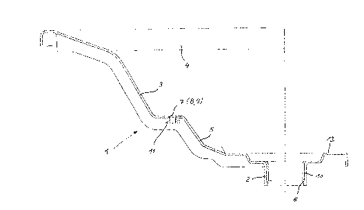
Figure 1 is a section through a steering-wheel skeleton
1 in accordance with the present invention; and
Figure 2 is a section through one embodiment of a spoke.
The sheet-steel blank 5 illustrated in Figure 1 has a
hub 2 with two layers 10 of material to make it thick and
rigid enough to accept a machined serration. Spokes 3 extend
up and out with steps left to accommodate such accessories as
an airbag in particular. Since spokes 3 and a rim 4 are CJ
shaped in section, the dimensions of the section can be
varied to provide sheet-steel blank 5 with enough strength
without varying its thickness.
Assembly has been facilitated by providing hub 2 with a
cone
4

CA 02208858 1997-06-20
6. One df the steps ~:az1 be prav~.ded with an. u.nt~~.readed bore 7, a
cutout 8 with a nut 1.1 embedded in i~. (as illustrated), or a
threaded bore 9.
AS will be evident from t~,e ~,llustration, the steering-wheel
slceletor~ has esserltia~.ly been shaped by stamping, punching, anal
bending para11e7, td its axis, meaning that all the tools in the
produCti.dn ~,ine are oriented ~.n Ghe same direction. This
considerably simplifies manu~aa~ure, and relatively comp~.a.cated
sheer-metal shapes can be rationally produced. The actual shape
can of course be varied to conform t4 di~~ere~rt rec~uirenGer~ts
without involving any other manufacturing pr~.x~c~.ple .
This does not mean, however, that processing in other
oxier~tatior~s cannot be included for specific purposes. 'the outer
edge of rim 4 or the right-hand edge of center 12 can be wrapped
inward fior instance.
~'~.gu~'e 2 ~.~ a section, through one e~lbodim~nt o~ a spoke 3.
Spoke 3 has been prd~rided with extra rigidity and protected from
damage by stamping and beading ~.ts edges 10 outward. It is
accordingly possible to acct~mtriadate th.e edges essentially away
from static or dynalttic stress, The curvature in the base 11 of
the section allows addita.o~sal anti.-strain hardeni~,g there. More
room is a~.so left to accommodate the outer layers of the steering
wheel.
The major advantage of both embc~~.~.ments is that the
st8e~'a.ng-wheel s~~eleton can be produced in one piece out of a
sa.ngle blank of sheet metal. The fiinal product wild. accordingly

CA 02208858 1997-06-20
. be homogeneous and will satis~~ a~i requirements. ~t wiii have no
joins that Could i~ad to failure az~d ~ec~uire extra inspection,
6

Representative Drawing
A single figure which represents the drawing illustrating the invention.
Administrative Status

2024-08-01:As part of the Next Generation Patents (NGP) transition, the Canadian Patents Database (CPD) now contains a more detailed Event History, which replicates the Event Log of our new back-office solution.

Please note that "Inactive:" events refers to events no longer in use in our new back-office solution.

For a clearer understanding of the status of the application/patent presented on this page, the site Disclaimer , as well as the definitions for Patent , Event History , Maintenance Fee  and Payment History  should be consulted.

Event History

Description Date
Time Limit for Reversal Expired 2003-06-20
Letter Sent 2002-06-20
Grant by Issuance 2001-02-06
Inactive: Cover page published 2001-02-05
Inactive: Final fee received 2000-10-27
Pre-grant 2000-10-27
Notice of Allowance is Issued 2000-09-11
Letter Sent 2000-09-11
Notice of Allowance is Issued 2000-09-11
Inactive: Approved for allowance (AFA) 2000-08-16
Amendment Received - Voluntary Amendment 2000-07-21
Inactive: S.30(2) Rules - Examiner requisition 2000-02-14
Letter Sent 1998-03-10
Application Published (Open to Public Inspection) 1997-12-21
Inactive: Multiple transfers 1997-12-17
All Requirements for Examination Determined Compliant 1997-09-23
Inactive: Single transfer 1997-09-23
Request for Examination Received 1997-09-23
Inactive: First IPC assigned 1997-09-23
Classification Modified 1997-09-23
Inactive: IPC assigned 1997-09-23
Request for Examination Requirements Determined Compliant 1997-09-23
Filing Requirements Determined Compliant 1997-09-05
Inactive: Filing certificate - No RFE (English) 1997-09-05
Application Received - Regular National 1997-09-04
Inactive: Courtesy letter - Evidence 1997-09-04

Abandonment History

There is no abandonment history.

Maintenance Fee

The last payment was received on 2000-04-06

Note : If the full payment has not been received on or before the date indicated, a further fee may be required which may be one of the following

  • the reinstatement fee;
  • the late payment fee; or
  • additional fee to reverse deemed expiry.

Please refer to the CIPO Patent Fees web page to see all current fee amounts.

Fee History

Fee Type Anniversary Year Due Date Paid Date
Application fee - standard 1997-06-20
Registration of a document 1997-09-23
Request for examination - standard 1997-09-23
Registration of a document 1997-12-17
MF (application, 2nd anniv.) - standard 02 1999-06-21 1999-03-23
MF (application, 3rd anniv.) - standard 03 2000-06-20 2000-04-06
Final fee - standard 2000-10-27
MF (patent, 4th anniv.) - standard 2001-06-20 2001-04-04
Owners on Record

Note: Records showing the ownership history in alphabetical order.

Current Owners on Record
TRW AUTOMOTIVE SAFETY SYSTEMS GMBH
Past Owners on Record
HERIBERT WERNER
KLAUS DREFAHL
MARTIN KREUZER
PETER HARTMANN
UDO LIESENFELD
Past Owners that do not appear in the "Owners on Record" listing will appear in other documentation within the application.
Documents

To view selected files, please enter reCAPTCHA code :


To view images, click a link in the Document Description column. To download the documents, select one or more checkboxes in the first column and then click the "Download Selected in PDF format (Zip Archive)" or the "Download Selected as Single PDF" button.

List of published and non-published patent-specific documents on the CPD .

If you have any difficulty accessing content, you can call the Client Service Centre at 1-866-997-1936 or send them an e-mail at CIPO Client Service Centre.


Document
Description 
Date
(yyyy-mm-dd) 
Number of pages   Size of Image (KB) 
Description 1997-06-20 6 218
Abstract 1997-06-20 1 18
Claims 1997-06-20 2 53
Drawings 1997-06-20 2 17
Cover Page 1998-01-26 1 46
Abstract 2000-07-21 1 16
Claims 2000-07-21 2 41
Cover Page 2001-01-08 1 31
Representative drawing 2001-01-08 1 6
Description 2000-07-21 6 230
Representative drawing 1998-01-26 1 7
Filing Certificate (English) 1997-09-05 1 165
Acknowledgement of Request for Examination 1998-03-10 1 179
Courtesy - Certificate of registration (related document(s)) 1998-03-10 1 118
Reminder of maintenance fee due 1999-02-23 1 111
Commissioner's Notice - Application Found Allowable 2000-09-11 1 163
Maintenance Fee Notice 2002-07-18 1 177
Correspondence 2000-10-27 1 29
Correspondence 1997-09-04 1 28