Language selection

Search

Patent 2209325 Summary

Third-party information liability

Some of the information on this Web page has been provided by external sources. The Government of Canada is not responsible for the accuracy, reliability or currency of the information supplied by external sources. Users wishing to rely upon this information should consult directly with the source of the information. Content provided by external sources is not subject to official languages, privacy and accessibility requirements.

Claims and Abstract availability

Any discrepancies in the text and image of the Claims and Abstract are due to differing posting times. Text of the Claims and Abstract are posted:

  • At the time the application is open to public inspection;
  • At the time of issue of the patent (grant).
(12) Patent Application: (11) CA 2209325
(54) English Title: SWITCH ACTUATOR FOR AN ELECTROMECHANICAL LOCKING UNIT
(54) French Title: COMMUTATEUR POUR SERRURES ELECTRO-MAGNETIQUES
Status: Deemed Abandoned and Beyond the Period of Reinstatement - Pending Response to Notice of Disregarded Communication
Bibliographic Data
(51) International Patent Classification (IPC):
  • E05B 47/00 (2006.01)
(72) Inventors :
  • SIVONEN, HANNU (Finland)
  • TIRKKONEN, JOUNI (Finland)
(73) Owners :
  • ABLOY OY
(71) Applicants :
  • ABLOY OY (Finland)
(74) Agent: KIRBY EADES GALE BAKER
(74) Associate agent:
(45) Issued:
(22) Filed Date: 1997-06-30
(41) Open to Public Inspection: 1998-01-12
Availability of licence: N/A
Dedicated to the Public: N/A
(25) Language of filing: English

Patent Cooperation Treaty (PCT): No

(30) Application Priority Data:
Application No. Country/Territory Date
962826 (Finland) 1996-07-12

Abstracts

English Abstract


A switch actuator for an electromechanical locking unit,
which locking unit includes a cylinder lock mechanism operated
mechanically by a key, a blocking device functionally dependent
on an electronic code to be fed from the key, and an electronic
control unit, which on the basis of the electronic code is
arranged to control the blocking device and which, under the
control of the switch actuator, is connectable to an electric
power source. The switch actuator comprises a permanent magnet
to be attached in association with the cylinder lock, a reed
switch located in the immediate vicinity of the permanent magnet
within the magnetic field provided thereby and a piece of
ferromagnetic material located in the key and arranged to be
placed in the vicinity of the permanent magnet when the key is
inserted into the cylinder lock so that it causes a change in the
magnetic field influencing the reed switch to provide a control
pulse, which is arranged to connect the electronic control unit
to the power source.


Claims

Note: Claims are shown in the official language in which they were submitted.


7
Claims
1. An electromechanical locking unit comprising:
a cylinder lock mechanism defining a key channel,
a key having a key shank for insertion in the key channel
for mechanical operation of the cylinder lock mechanism, said key
embodying a code,
a blocking means for blocking operation of the cylinder lock
mechanism,
an electronic control unit responsive to a code to control
the blocking means,
a means for feeding the code embodied in the key
electronically from the key to the electronic control unit,
an electric power source for supplying operating current to
the electronic control unit,
a switch arrangement for controlling supply of operating
current from the electric power source to the electronic control
unit, said switch arrangement including a switch having an open
condition in which it isolates the control unit from the electric
power source and a closed condition in which it supplies
operating current from the electric power source to the control
unit, a magnet responsive means in the vicinity of the cylinder
lock mechanism for controlling the condition of the switch in
dependence on magnetic field influencing the magnet responsive
means, and a permanent magnet means establishing a magnetic field
in the vicinity of the magnet responsive means, and
a ferromagnetic means on or in the key, the ferromagnetic
means altering the magnetic field established by the permanent
magnet means such as to cause the magnet responsive means to
place the switch in the closed condition when the key shank is
inserted in the key channel.
2. An electromechanical locking unit according to claim 1,
wherein the switch is responsive to an electrical pulse to change
from its open condition to its closed condition, the switch
arrangement comprises a capacitor and the magnet responsive means
comprises a reed switch connected between the power source and
the capacitor, whereby a change in state of the reed switch

8
causes the capacitor to supply an electrical pulse to the control
switch.
3. An electromechanical locking unit according to claim 2,
wherein the reed switch and the permanent means are mutually
located so that the magnetic field established by the permanent
magnet means biases the reed switch to an open state and the reed
switch changes to a closed state when the magnetic field
established by the permanent magnetic means is altered by the
ferromagnetic means when the key is inserted in the key channel.
4. An electromechanical locking unit according to claim 1,
wherein the permanent magnet means comprises two permanent magnet
elements angularly spaced about the key channel and wherein the
magnet responsive means is positioned substantially between the
two permanent magnet elements.
5. An electromechanical locking unit according to claim 4,
wherein the two permanent magnet elements are angularly spaced at
an included angle of at least about 120° and the magnet
responsive means is positioned in the included angle between the
permanent magnet elements.
6. An electromechanical locking unit according to claim 1,
comprising a protective element protecting the cylinder lock
mechanism from the exterior and wherein the magnet responsive
means and the permanent magnet means are located inside the
protective element and upstream of the cylinder lock mechanism
with respect to the direction of insertion of a key in the key
channel.
7. An electromechanical locking unit according to claim 6,
wherein the magnet responsive means comprises a reed switch and
the reed switch and the permanent magnet means are integrated in
a switch unit.

9
8. An electromechanical locking unit according to claim 1,
wherein the key has a key bow from which the key shank extends
and the ferromagnetic means comprises a piece of ferromagnetic
material attached to the key shank at its end nearer the key bow.
9. An electromechanical locking unit according to claim 8,
wherein the ferromagnetic material is iron.
10. An electromechanical locking unit according to claim 1,
wherein the key has a key bow from which the key shank extends
and the ferromagnetic means comprises a sleeve-like piece of
ferromagnetic material fitted around the key shank at its end
nearer the key bow.
11. An electromechanical locking unit according to claim
10, wherein the ferromagnetic material is iron.
12. An electromechanical locking unit according to claim 1,
wherein the ferromagnetic means comprises a piece of
ferromagnetic material attached to the key.
13. An electromechanical locking unit according to claim 1,
wherein the switch is a pulse controlled switch and the locking
unit further comprises a control means for placing the pulse
controlled switch in its open condition after a locking operation
has been completed.
14. An electromechanical locking unit according to claim 1,
wherein the electric power source is a battery.
15. An electromechanical locking unit according to claim 1,
wherein the electric power source is a rechargeable battery.

Description

Note: Descriptions are shown in the official language in which they were submitted.

Sorry, the description for patent document number 2209325 was not found. Text is not available for all patent documents. The current dates of coverage are on the Currency of Information  page
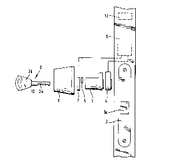
Representative Drawing
A single figure which represents the drawing illustrating the invention.
Administrative Status

2024-08-01:As part of the Next Generation Patents (NGP) transition, the Canadian Patents Database (CPD) now contains a more detailed Event History, which replicates the Event Log of our new back-office solution.

Please note that "Inactive:" events refers to events no longer in use in our new back-office solution.

For a clearer understanding of the status of the application/patent presented on this page, the site Disclaimer , as well as the definitions for Patent , Event History , Maintenance Fee  and Payment History  should be consulted.

Event History

Description Date
Inactive: IPC expired 2020-01-01
Inactive: IPC from MCD 2006-03-12
Application Not Reinstated by Deadline 2001-07-03
Time Limit for Reversal Expired 2001-07-03
Deemed Abandoned - Failure to Respond to Maintenance Fee Notice 2000-06-30
Inactive: Prior art correction 2000-06-14
Inactive: Cover page published 1999-10-06
Application Published (Open to Public Inspection) 1998-01-12
Inactive: IPC assigned 1997-10-01
Classification Modified 1997-10-01
Inactive: First IPC assigned 1997-10-01
Filing Requirements Determined Compliant 1997-09-11
Letter Sent 1997-09-11
Inactive: Filing certificate - No RFE (English) 1997-09-11
Application Received - Regular National 1997-09-10

Abandonment History

Abandonment Date Reason Reinstatement Date
2000-06-30

Maintenance Fee

The last payment was received on 1999-06-17

Note : If the full payment has not been received on or before the date indicated, a further fee may be required which may be one of the following

  • the reinstatement fee;
  • the late payment fee; or
  • additional fee to reverse deemed expiry.

Please refer to the CIPO Patent Fees web page to see all current fee amounts.

Fee History

Fee Type Anniversary Year Due Date Paid Date
Application fee - standard 1997-06-30
Registration of a document 1997-06-30
MF (application, 2nd anniv.) - standard 02 1999-06-30 1999-06-17
Owners on Record

Note: Records showing the ownership history in alphabetical order.

Current Owners on Record
ABLOY OY
Past Owners on Record
HANNU SIVONEN
JOUNI TIRKKONEN
Past Owners that do not appear in the "Owners on Record" listing will appear in other documentation within the application.
Documents

To view selected files, please enter reCAPTCHA code :


To view images, click a link in the Document Description column. To download the documents, select one or more checkboxes in the first column and then click the "Download Selected in PDF format (Zip Archive)" or the "Download Selected as Single PDF" button.

List of published and non-published patent-specific documents on the CPD .

If you have any difficulty accessing content, you can call the Client Service Centre at 1-866-997-1936 or send them an e-mail at CIPO Client Service Centre.


Document
Description 
Date
(yyyy-mm-dd) 
Number of pages   Size of Image (KB) 
Abstract 1997-06-30 1 28
Claims 1997-06-30 3 131
Description 1997-06-30 6 315
Drawings 1997-06-30 2 37
Cover Page 1999-10-01 1 37
Representative drawing 1999-10-01 1 5
Courtesy - Certificate of registration (related document(s)) 1997-09-11 1 118
Filing Certificate (English) 1997-09-11 1 165
Reminder of maintenance fee due 1999-03-02 1 111
Courtesy - Abandonment Letter (Maintenance Fee) 2000-07-31 1 184