Note: Descriptions are shown in the official language in which they were submitted.
CA 02209558 2000-09-28
- 1 -
Wavelength Monitoring and Control Assembly for WDM Optical
Transmission Systems
FIELD OF THE INVENTION
This invention relates to a wavelength monitoring
assembly for providing a control signal for wavelength
stabilization of a laser source, with application for WDM
optical transmission systems.
io BACKGROUND OF THE INVENTION
Optical fiber communication systems provide for
low loss and very high information carrying capacity. In
practice, the bandwidth of optical fiber may be utilized
by transmitting many distinct channels simultaneously
i5 using different carrier wavelengths. The associated
technology is called wavelength division multiplexing
(WDM). In a narrow band WDM system 8, 16 or more
different wavelengths are closely spaced to increase fiber
transmission capacity.
2o The wavelength bandwidth that any individual
channel occupies depends on a number of factors, including
the impressed information bandwidth, and margins to
accommodate for carrier frequency drift, carrier frequency
uncertainty, and to reduce possible inter-channel cross-
25 talk due to non-ideal filters.
To maximize the number of channels, lasers with
stable and precise wavelength control are required to
provide narrowly spaced, multiple wavelengths.
Some laser sources, for example distributed
3o feedback (DFB) lasers, exhibit wavelength drift over time,
in excess of the requirements for narrow band WDM. The
wavelength of the device tends to change with aging under
continuous power. Since telecommunication systems are
expected to have a lifetime of the order of 25 years,
35 wavelength control must be added to the laser transmitter
to ensure minimum cross-talk between narrowly spaced
channels over extended time periods.
CA 02209558 2000-09-28
- 2 -
Single wavelength optical communications systems
are widely used in the industry. Ideally, systems
designers seek minimum disruption of existing systems and
compatibility with existing packaging in development of
WDM systems.
Typically, known laser wavelength monitoring and
stabilization systems are based on a unit external to the
standard package of a laser source (transmitter). One
commercially available system for monitoring and control
to of the wavelength of a semiconductor laser is an assembly
based on crystal gratings. For example, in a known system
manufactured by Accuwave, and described in the product
literature, a wavelength locker unit is provided which
comprises a lithium niobate crystal in which two Bragg
i5 gratings are written, illuminated by a collimated beam
from a laser source coupled to the assembly, and two
photodetectors. Each grating has a slightly different
Bragg wavelength and angle relative to the input beam.
The output reflected from the gratings is directed to the
2o two detectors and the differential output is used to
provide feedback control to the laser. Wavelength
stability of better than l0pm can be achieved with the
control loop. However, the locker utilizes a separate
unit from the transmitter, and thus requires external
25 coupling to the laser or light source. Moreover, the unit
is designed for a specific wavelength, as specified by the
grating parameters. Different units are required for
different wavelengths.
Another known type of wavelength
3o monitoring/control assembly is based on a fiber grating.
For example, U.S. Patent 5,828,681 to Epworth et al.,
relates to an external cavity type laser whose external
reflector is provided by a Bragg reflector located in an
optical fibre butted to an anti-reflection coated facet of
35 the semiconductor laser. The grating is placed far enough
from the laser that the longitudinal modes are so closely
spaced that the laser operates multimode with so many
CA 02209558 2000-09-28
- 3 -
modes as to make mode partition noise negligible. Another
U.S. Patent 5,715,265 to Epworth et al., relates to using
a chirped fiber grating for equalization and laser
frequency stabilization.
Fabrication of fiber grating assemblies is
complex. As with the crystal grating system mentioned
above, fibre gratings are fabricated to match the specific
wavelength of the transmitter, and the assembly is
therefore wavelength specific.
io Another system for stabilization of a
semiconductor laser is described in U.S. Patent 4,309,671
to Malyon which uses a pair of matched photodiodes and two
beam splatters. The first beam splatter and first
photodiode monitor power, and a second beam splatter, a
i5 frequency dependent filter and second photodiode are used
to monitor wavelength changes. The outputs of the matched
photodiodes are fed via amplifiers to a subtractor
amplifier and the output is fed as negative feedback to
the amplifier controlling operation of the laser.
2o Other known systems are based on a filter element
such as a Fabry-Perot etalon. For example, U.S. Patent
5,331,651 to Becker et al. describes the use of a Fabry-
Perot etalon for fine tuning in conjunction with a grating
for coarse tuning of the output of a laser.
25 In a system described in U.S. Patent 5,438,579 to
Eda et al., a Fabry-Perot etalon is used with a single
photodetector to generate a signal used to lock onto one
peak of a semiconductor laser, requiring collimated beams.
Hill et al., in U.S. Patent 4,839,614 describe a system
3o for referencing frequencies of radiation from multiple
sources relative to a reference source, using a filter
element such as a Fabry-Perot etalon and a corresponding
plurality of detectors.
Another system for laser wavelength stabilization
3s is described in U.S. Patent 4,914,662 to Nakatani et al.
which involves spectroscopically processing the output of
a variable wavelength laser and measuring a spatial
CA 02209558 2000-09-28
- 4 -
distribution using image processing apparatus, and then
comparing the distribution to that of a reference light
source of fixed wavelength. The latter image processing
system is complex, and not readily compatible with
providing a low cost, compact unit.
Japanese Patent JP 04-157780 relates to a
frequency stabilizer for semiconductor laser, without
using external modulating means, and is based on an
inclined Fabry-Perot etalon on which the laser source is
to incident, and two photo-detectors to detect respectively
the transmitted and reflected signals. By subtracting
outputs of the two detectors, a signal is provided for
controlling the oscillation frequency. Resonator length
is altered by changing the inclination of the etalon to
i5 allow for tunability. The implementation of this system
for minimum space requires using the FP at a relatively
large angle, with decreased stability in terms of center
wavelength and bandwidth. On the other hand, a small FP
angle requires added components and space, as shown in
2o Figure 1B of this patent application. Also, independent
detectors are used, with potentially different response
and aging characteristics.
Consequently, various existing systems for
wavelength stabilization are known using a crystal
z5 grating, fiber grating or etalon based arrangement. The
grating based systems lack wavelength tunability and many
systems are based on relatively large control units
external to a packaged laser source, with concurrent
coupling, space and power dissipation problems. While
3o etalon based systems provide tunability, none of the known
configurations are sufficiently compact to incorporate in
known standard packages without disruption.
SUN~IARY OF THE INVENTION
35 The present invention seeks to provide a compact
wavelength monitoring and control assembly, preferably for
CA 02209558 2000-09-28
- 5 -
integration within a small semiconductor laser package and
for application in WDM optical transmission systems.
Thus according to one aspect of the present
invention there is provided a wavelength monitoring and
s control assembly for an optical system comprising a laser
emission source for generating a divergent beam, the
assembly comprising: first and second photodetectors
spaced apart by a specific separation, and located at a
specific distance from the emission source; a narrow
io bandpass wavelength selective transmission filter element
of Fabry-Perot structure located between the source and
the photodetectors, the filter element being tilted at an
angle B relative to the optical axis of the emission
source to provide an angular dependence of the wavelength
i5 transmission of the filter, for illuminating the
photodetectors with two different parts of the divergent
beam, incident at the filter at different angles, and
transmitted by the filter, whereby a change in wavelength
from the source is converted to a difference in
2o transmission detected by the photodetectors; and a control
loop for feedback of a difference signal generated by the
first and second photodetectors in response to a change in
wavelength of the emission source to control means of the
emission source to provide wavelength stabilization of the
25 source .
Thus a simple and compact wavelength monitoring
and control assembly for a laser emission source is
provided. The photodetectors are illuminated through the
tilted narrowband pass filter with a slightly diverging
3o beam. Thus, wavelength variation of the laser emission
source is converted into differential photocurrent changes
in the two photodetectors. The wavelength of the input
beam is monitored by the relative responses of the two
detectors. The differential output signal of the two
35 detectors is used in a feedback loop to stabilize the
wavelength of the source to a desired target wavelength,
i.e. through a signal sent back to the laser
CA 02209558 2000-09-28
- 6 -
(transmitter), e.g. via active area temperature changes,
or current changes, to correct for wavelength drift.
This assembly allows for precise optical
monitoring of the wavelength to provide a control signal
for wavelength stabilization, to maintain the laser
wavelength within the limits required to reduce cross-talk
for use in, for example, a WDM optical transmission
system. A difference signal is advantageous also to
provide immunity to fluctuations in output power.
io The narrow bandpass wavelength selective
transmission filter element is required to be a Fabry-
Perot structure. The photodetectors are preferably a
matched pair of photodiodes. Through the angular
dependence of the wavelength transmission of the Fabry-
i5 Perot etalon, a wavelength variation from the source is
converted to a transmission loss, and the wavelength
change is detected as a power change. Thus, the device
functions as an optical wavelength discriminator in which
the detector converts optical energy to current for a
2o feedback loop for controlling the light source. For
wavelength stabilization, the differential output of the
two photodetectors is used in a feedback loop to stabilize
the wavelength of the laser source to a desired target
wavelength.
25 Beneficially, the angle of inclination of the
filter is adjustable to provide tunability of the
predetermined wavelength. Since the wavelength selective
filter element is a Fabry-Perot etalon, whose transmission
characteristics are dependent on the angle of the etalon
3o relative to the beam, the assembly provides for tunability
by adjusting the angle of the etalon. Also, the multiple
transmission peaks of an etalon with, for example, 4nm
spacing, can be used for multiple wavelengths. That is,
simultaneous stabilization points are attainable for a
35 plurality of predetermined wavelengths determined by
wavelength spacings of the multiple transmissive peaks
characteristic of the Fabry-Perot filter.
CA 02209558 2000-09-28
The assembly is simple to manufacture relative to
fabrication of fiber grating systems for wavelength
stabilization. This approach provides a dither free
discrimination scheme, which also avoids frequency
modulation and demodulation steps.
Advantageously, the photodetectors are a matched
pair of photodiodes. When the gain of each of the two
photodetectors is independently adjustable, the
predetermined wavelength may be selected by setting
io unequal gains for the two photodetectors.
Optionally, a lens is disposed between the
emission source and the transmission filter element to
control divergence of the laser emission source. The
divergence of the beam is controlled to optimize
i5 performance and power detection. A larger spot size is
preferable to provide a more ideal filter shape to obtain
more efficient power transfer.
The laser emission source may be an output facet
of semiconductor laser, or alternatively a cleaved or
zo tapered single mode fibre.
Advantageously, when the laser emission source
comprises a semiconductor laser provided within a package,
the wavelength monitoring assembly is provided within the
same package to provide an integral unit. While use of
25 the assembly as an external reference unit is feasible,
polarization maintaining fibers and couplers are ideally
required to avoid polarization dependence.
Thus, according to another aspect of the present
invention there is provided a wavelength monitoring and
3o control assembly for wavelength stabilization of a laser
emission source, the assembly comprising: a package, and
integrated within the package: a laser emission source
for generating a divergent beam; first and second coplanar
photodetectors having a specific diameter and separation,
35 and located at a specific distance from the emission
source; and a narrow bandwidth, wavelength selective
transmission filter element of Fabry-Perot structure
CA 02209558 2000-09-28
disposed between the emission source and the
photodetectors, the filter element being tilted at an
angle B relative to the optical axis of the emission
source to provide an angular dependence of the wavelength
transmission of the filter, for illuminating the two
photodetectors with two different parts of the divergent
beam incident at the filter at different angles and
transmitted by the filter, whereby a change in wavelength
from the source is converted to a difference in
io transmission detected by the photodetectors; means for
generating a difference signal from the first and second
photodetectors, the difference signal generated by the
response of the photodetectors being dependent on a change
in wavelength transmission by the wavelength transmission
selective filter, to provide a signal via a feedback loop
for wavelength stabilization of the laser emission source.
Because the monitoring assembly is simple and
compact, an important advantage is that the assembly may
be co-packaged with the laser source in an existing
2o transmitter module, i.e. in a standard laser package.
This is particularly useful in adapting existing
transmitter modules, as used for single wavelength
transmission systems, for use with additional components
for WDM without taking up additional space and with
minimum disruption of existing systems.
Long term reliability of the assembly is expected
to meet lifetime requirements for WDM systems.
BRIEF DESCRIPTION OF THE DRAWINGS
3o Figure 1 shows a schematic diagram of part of a
wavelength monitoring assembly according to a first
embodiment of the present invention;
Figure 2 shows transmission curves of etalon for
the signal at two wavelengths;
Figure 3 shows the corresponding difference
signal from the first and second photodetectors;
CA 02209558 2000-09-28
- 9 -
Figure 4 shows a schematic of part of the
assembly similar to that shown in Figure 1, which defines
coordinates and parameters for design of the assembly; and
Figure 5 shows a schematic of the test system for
a wavelength stabilization assembly according to a second
embodiment of the present invention.
DESCRIPTION OF THE EMBODIMENTS
Part of a wavelength monitoring assembly 10
io according to a first embodiment of the present invention
is shown in Figure 1. The assembly comprises a divergent
source 12 of laser emission, that is, a semiconductor
laser facet 14 of a DFB laser, as shown, or alternatively
an output facet of a single mode fibre (SMF). An optional
i5 lens 16 provides for controlling the divergence of the
output beam of the laser source, which is directed to a
narrow bandpass, wavelength selective transmission filter
element 18. The latter is preferably a Fabry-Perot (FP)
resonator, which is a structure comprising a spacer layer
2o sandwiched between two highly reflecting layers. It is
constructed for example as a multilayer single cavity
filter type, where an all-dielectric mirror/spacer/mirror
structure is deposited on a glass substrate.
Alternatively, a solid etalon type is used, in which
25 mirrors are deposited on both sides of a glass spacer
plate.
The transmitted divergent beam is directed onto
first and second similar coplanar photodetectors (P1) 20
and (P2) 22 having a specific diameter and separation,
3o which are mounted on a common support 24 at a specific
distance from the FP etalon, as shown schematically in
Figure 1.
Since the wavelength of the light source
determines how much the beam is transmitted by the FP
35 filter, the signal received at each detector 20 and 22 is
dependent on the wavelength emitted from the light source,
Thus, through the angular dependence of the wavelength
CA 02209558 2000-09-28
- 10 -
transmission of the Fabry-Perot etalon, a wavelength
variation from the source is converted to a transmission
change, and the wavelength change is detected as a power
change by the two photodetectors. The output signals from
the two photodetectors are used to generate a difference
signal in subtractor amplifier 26 which is fed to a
feedback loop 28 for controlling the output wavelength of
the laser source. By arranging that the transmission
detected by both detectors is the same at a selected
io wavelength, the difference signal is set to be zero at the
predetermined wavelength, i.e. the locked wavelength. The
locked wavelength can be set, with equivalent stability,
to different values by using unequal gains for
photodetectors P1 and P2. If the source wavelength
i5 changes, the differential signal generated by the two
detectors, i.e. the error signal, is wavelength dependent
and can be used to monitor the wavelength of the light
source. The device functions therefore as an optical
wavelength discriminator in which the photo-detectors
2o convert optical energy to a current for a feedback loop
for controlling the laser source.
Schematic representations of the transmission
curves and difference signal generated by the two
detectors are shown respectively in Figures 2 and 3.
25 Figure 2 shows the transmission curves of the two
detectors where T is the transmission from source to
detectors, where T1 and T2 represent the transmission
curves for the individual detectors P1 and P2 which have a
maximum transmission at T1M and T2M at ~., and ~,,. The
3o difference signal from the two detectors is represented in
Figure 3. At the desired locked wavelength, the slope SR
of the difference at the locking point ~,R is
D~T~ - Ti
SR -
and the near linear region between ~,~ and ~,Z defines the
35 useful range of control obtained, for example, by using
unequal photodetector gains.
CA 02209558 2000-09-28
- 11 -
Figure 4 defines coordinates and a number of
relevant configuration parameters for an assembly
including a divergent emission source, e.g. single mode
fibre, lens, filter and pair of photodetectors. A
s schematic of an assembly and test set up for wavelength
stabilization of a DFB laser, including a control loop, is
shown in Figure 5.
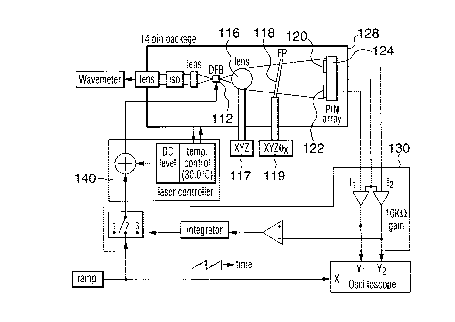
In Figure 5, the wavelength stabilization
assembly comprising a lens 116, FP etalon 118 and pair of
to PIN diodes 120 and 122 is co-packaged with a DFB laser
source 112 within a single package 128 which is a standard
14 pin package. The matched diode pair 120 and 122 are
coplanar, and mounted close together on a common support
124. Output signals from the two diodes are fed to a
i5 subtractor amplifier 130 to generate a difference signal
which is fed back to the laser controller 140 for
controlling the output wavelength of the laser. Other
components shown in Figure 5 include test apparatus used
in designing optimum configurations for the prototype.
zo Preferably the mounting 117 for the lens 116 and mounting
119 for the FP etalon 118 are adjustable. Changing the
tilt angle eX of the FP etalon provides for tuning of the
target wavelength as described below.
As shown in Figure 4, the divergent source 13,
z5 has a generally Gaussian pattern, which may be elliptical
(laser) or circular (single-mode fibre).
The Fabry-Perot etalon has parameters of
thickness t, refractive index n, reflectivity R, internal
transmission A, x axis tilt angle BxFp which is determined
3o by the choice of FP design and the required ~,R, and y axis
tilt angle 9FP which may be arbitrarily chosen to be 0°.
The two detectors have nominal y axis positions of y01 =0
and yp2 =0 which are arbitrarily chosen.
Other configuration parameters are chosen in
35 accordance with these parameters and the desired
specifications, i.e. the required transmission curves.
CA 02209558 2000-09-28
- 12 -
These parameters include: the focal length of
the lens f, z axis position Sl, x axis tilt angle 9x~, Y
axis tilt angle 8', the z axis position of the etalon zFp,
and assuming the detectors are circular, the radius r of
s the photodetectors, their z axis position zo, and x axis
positions xoi and x~2.
Each detector has a diameter of d1 and d2
respectively, and the pair of detectors are coplanar, and
separated centre to centre by a distance D, located a
io distance 1 from the light source, the FP filter is tilted
at an angle of B from the normal to the plane of the two
detectors.
Factors influencing the performance of the
assembly include the FP etalon tilt angles in the x and y
15 axis, the FP index change with temperature, the detector x
and y axis offset, lens position and tilt, and the
detector z axis position. T is the transmission from the
source to a detector and includes the coupling loss due to
limited detector size.
2o The desired locked wavelength ~.R has a specific
target value, e.g. 1557.0 nm. The ratios T1R/T1M and
T2R/T2M are specified to be a half, for a first
approximation. The slope at the locking point SR is also
of interest because of its impact on the loop gain. A
25 high slope is generally desirable. ~,2-~.~ expresses the
tuning range over which T1 and T2 can be compared. T1M
and T2M allow the estimation of absolute power, and
therefore S/N for given detector characteristics.
The assembly is wavelength tunable by changing
3o the angle of inclination B of the filter element, for
example, tilt angle 8x as shown in Figure 5, where the
filter element, i.e. the etalon, is mounted on an
adjustable support with four degrees of freedom, including
angular adjustment. In the test set up, the lens was also
35 movable in 3 dimensions. Once the assembly is aligned for
a particular target wavelength, the components, including
CA 02209558 2000-09-28
- 13 -
the filter and the lens, are fixed in place using thin
layers of adhesive.
Wavelength tunability at the module alignment
stage is an advantage over known grating based wavelength
s control units.
Furthermore, because the transmission of a Fabry-
Perot filter is characterized by a series of transmissive
peaks at regular wavelengths intervals, for example, at
4nm spacing, simultaneous stabilization points are
to attainable for a plurality of predetermined wavelengths
which are determined by wavelength spacings of the
multiple transmissive peaks characteristic of the Fabry-
Perot filter.
Thus, the minimum required components for the
15 wavelength discrimination scheme are a narrow band
transmission filter (etalon) and two closely spaced
detectors, preferably a matched pair of photodiodes, and a
control loop which responds to the difference signal from
the pair of photodetectors. A Fabry-Perot etalon is
zo required to provide suitable characteristics of the
wavelength selective filter element.
The light source may for example be a front facet
of a semiconductor laser, for example a DFB laser, or the
cleaved or tapered end of a single mode fibre. If
25 required, the divergence of the emission source is
controlled by a lens as shown in Figure l, which may be
any suitable aspherical lens, a cylindrical lens, a
spherical lens, or a graded index lens, of glass or
plastic. A larger spot size gives the filter a shape
3o closer to desired, and provides better power transfer to
the detectors. Alternatively, the assembly may be
provided without a lens if the divergence of the emission
source is satisfactory to meet these requirements.
Beneficially collimated beams are not required,
35 potentially reducing the number of components and size of
the assembly.
CA 02209558 2000-09-28
- 14 -
In the assembly described above, the compactness
and simplicity of the configuration allows for co-
packaging with a laser source in a standard laser
transmitter package. This is a particular advantage for
s integration with existing systems. Some of the benefits
of the same configuration may be obtained in a unit
external to the laser source, but because coupling to an
external unit is polarization dependent, couplers or
fibers that are polarization maintaining would then be
to preferred.
Thus a simple and compact wavelength monitoring
and control assembly for a laser emission source is
provided comprising a narrow bandpass, wavelength
selective transmission filter element, for example a
15 Fabry-Perot etalon, through which a non-collimated beam
from the laser source is directed onto two closely spaced
photodetectors. For wavelength stabilization, the
differential output of the two photodetectors generated by
the change in transmission of the filter element with a
2o change in wavelength is used in a feedback loop to
stabilize the wavelength of the laser source to a desired
target wavelength. Optionally, wavelength tunability is
provided by changing the angle of inclination of the
Fabry-Perot etalon relative to the laser source. The
2s system is compact and may be co-packaged within the same
package as a laser emission source, overcoming coupling,
space and power dissipation problems common with known
external semiconductor laser wavelength control units.
While specific embodiments have been described in
3o detail, it will be understood that variations and
modifications of the embodiments may be made within the
scope of the following claims.