Language selection

Search

Patent 2209833 Summary

Third-party information liability

Some of the information on this Web page has been provided by external sources. The Government of Canada is not responsible for the accuracy, reliability or currency of the information supplied by external sources. Users wishing to rely upon this information should consult directly with the source of the information. Content provided by external sources is not subject to official languages, privacy and accessibility requirements.

Claims and Abstract availability

Any discrepancies in the text and image of the Claims and Abstract are due to differing posting times. Text of the Claims and Abstract are posted:

  • At the time the application is open to public inspection;
  • At the time of issue of the patent (grant).
(12) Patent Application: (11) CA 2209833
(54) English Title: DRINK-THROUGH LID FOR CONTAINER
(54) French Title: COUVERCLE OUVRANT POUR CONTENANT A BOIRE
Status: Deemed Abandoned and Beyond the Period of Reinstatement - Pending Response to Notice of Disregarded Communication
Bibliographic Data
(51) International Patent Classification (IPC):
  • B65D 47/20 (2006.01)
  • B65D 43/02 (2006.01)
(72) Inventors :
  • SCHAEFER, ROBERT J. (United States of America)
  • PENDERGRASS, WILLIAM B. (United States of America)
(73) Owners :
  • SWEETHEART CUP COMPANY INC.
  • SWEETHEART CUP COMPANY INC.
(71) Applicants :
  • SWEETHEART CUP COMPANY INC. (United States of America)
  • SWEETHEART CUP COMPANY INC. (United States of America)
(74) Agent: BORDEN LADNER GERVAIS LLP
(74) Associate agent:
(45) Issued:
(22) Filed Date: 1997-07-08
(41) Open to Public Inspection: 1998-01-30
Availability of licence: N/A
Dedicated to the Public: N/A
(25) Language of filing: English

Patent Cooperation Treaty (PCT): No

(30) Application Priority Data:
Application No. Country/Territory Date
08/689,142 (United States of America) 1996-07-30

Abstracts

English Abstract


A container lid includes a flap region that is selectively displaceable
between a static raised position and a static depressed position. A flap is cut out
of the flap region and is substantially integral with the flap region when the flap
region is in the static raised position. When the flap region is displaced to the
static depressed position, the flap separates from the flap region enabling liquid
to flow therethrough. When the flap region is returned to the static raised
position, the flap is again substantially integral with the flap region to thereby
close the lid and prevent liquid from escaping. A knob is provided preferably
integral with the flap region to facilitate displacement of the flap region.


French Abstract

Cette invention concerne un couvercle de contenant comportant une partie mobile entre une position relevée et une position abaissée. Une pièce découpée dans la partie mobile est en majeure partie solidaire de la partie mobile lorsque celle-ci est relevée. Lorsque la partie mobile est abaissée, la pièce découpée se désolidarise de la partie mobile pour permettre l'écoulement du liquide contenu dans le contenant. Lorsque la partie mobile est relevée à nouveau, la pièce découpée redevient sensiblement solidaire de cette partie et obture alors le couvercle pour empêcher le liquide de s'échapper. De préférence, un bouton solidaire de la partie mobile est prévu pour faciliter le déplacement de cette partie.

Claims

Note: Claims are shown in the official language in which they were submitted.

(g) CLAIMS
1. A container lid comprising:
a web portion having a flap region selectively displaceable between
a static raised position and a static depressed position;
a flap cut out of said flap region, said flap being substantially
integral with said flap region when said flap region is in said static raised
position, and said flap being separated from said flap region when said flap
region is in said static depressed position; and
a knob secured to said flap region, said knob being graspable to
facilitate displacement between said static depressed position and said static
raised position.
2. A container lid according to claim 1, wherein said knob comprises
at least two side walls extending substantially perpendicular from said flap
region, said side walls being deformable.
3. A container lid according to claim 2, wherein said knob is diamond
shaped.
4. A container lid according to claim 1, wherein said knob is integral
with said flap region.
5. A container lid according to claim 1, wherein a center of said flap
region is raised above said web portion in said raised position and said center is
depressed below said web portion in said depressed position.

6. A container lid according to claim 1, wherein said web portion is
substantially flat and said flap region is shaped substantially as a spherical cap
segment, wherein a center of said flap region is raised above said web portion in
said raised position and said center is depressed below said web portion in saiddepressed position.
7. A container lid according to claim 6, wherein said flap region has a
diameter at said web portion of between 0.5-2".
8. A container lid according to claim 7, wherein said flap region has a
diameter at said web portion of about 1".
9. A container lid according to claim 1, wherein said knob comprises a
vent hole.
10. A container lid comprising:
a web portion having a flap region selectively displaceable between
a static raised position and a static depressed position; and
a flap cut out of said flap region, said flap being substantially
integral with said flap region when said flap region is in said static raised
position, and said flap being separated from said flap region when said flap
region is in said static depressed position.
11. A container lid according to claim 10, wherein a center of said flap
region is raised above said web portion in said raised position and said center is
depressed below said web portion in said depressed position.

12. A container lid according to claim 10, wherein said web portion is
substantially flat and said flap region is shaped substantially as a spherical cap
segment, wherein a center of said flap region is raised above said web portion in
said raised position and said center is depressed below said web portion in saiddepressed position.

Description

Note: Descriptions are shown in the official language in which they were submitted.


CA 02209833 l997-07-08
(a) ll rLE OF THE INVENTION
DR~K-T~ROUGEl LID FO~ CONTAI~ER
(b) lECHNICAL F~ELD TO WHICH THE lNVENTlON RELATES
The present invention relates to lids for liquid containers and, more
s particularly, to a drink-through lid for a paper container that is configured to
enable automatic opening and closing of a drink-through flap.
(c) BACKGROUND ART
Many drink through lids have been proposed for paper containers to
enable a user to drink, for example, coffee without requiring the user to remove10 the lid. A drink-through lid helps to prevent spillage of the liquid as well as to
prevent heat dissipation (in the case of a hot liquid e . g . coffee).
In U.S. Patent i'~'o. 3,797,696, a container lid is disclosed that includes an
arcuate center section and a plurality of radially extending fingers which
IS are normally inte~ral with the w-eb portion of Ihe lid. When the extension is
pressed, the radially extending fingers are urged downwardly and away from
the ~veb portion of the lid. The downward extension of the radially extending
fingers away from the web portion exposes a series of liquid discharge slots
in the web portion . When the user relaxes the central extension , the
~o radially extending fingers retu~ to their normal or sealing position to close the liquid discharge slots
This structure, however, requires that the user maintain the central
extension in a depressed position in order to discharce liquid through the slots~s With this structure, it is difficult and somewhat aw~-~-ard to press the central
extension while drinking from the container.
012s3~oo1

CA 02209833 l997-07-08
(~1) DESCE~IPTION OF THE INVENTION
It is therefore an object of the invention to provide a container lid for a
paper container that obviates the disadvantages associated with the above-noted
and other prior art container lids. In this regard, it is an object of the invention to
provide a container lid that is selectively movable bet~veen a raised position and a
depressed position without requirino the user to maintain contact with the lid
while drinl;ing from the container (i.e., a static raised position and a static
depressed position).
o These and other objects of the invention are achieved by providing a
container lid including a web portion having a flap region selectively displaceable
between a static raised position and a static depressed position, a flap cut out of
the flap region that is substantially integral with the flap region when the flap
region is in the static raised position and separated from the flap region when the
flap region is in the static depressed position. A ~;nob may be provided securedto the flap region, which is gr2spable to facilit2te dis?lacement between the static
de?ressed posilion and the static raised position.
The knob preferably includes at least t~vo side walls extending
~o substantially perpendicular from the flap region that are deformable. In this
regard, the knob is preferably diamond shaped. ~loreover, the knob may be
inte(~ral with the flap region. A vent hole may be pro~,-ided in the knob so that the
vent hole is disposed spaced from the web portion.
A center of the flap region is preferably raised above the web portion in
the raised position and the center is depressed below the ~eb portion in the
01~37001

. CA 02209833 1997-07-08
depressed position. The web portion may be substantially flat and the flat region
shaped substantially as a spherical cap segment, wherein a center of the flap
region is raised above the web portion in the raised position, and the center isdepressed below the web portion in the depressed position.
(e) DESCRlPTION OF THE FIGURES
In the accompanying drawings:
to FIGI,~RE 1 is a plan view of an e~cemplary container lid according to the
present invention;
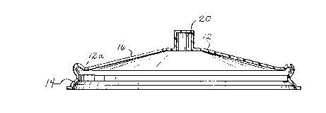
FIGI,~RE 2 is a cross-sectional view of the lid taken along line II-II in
FIGIJRE 1 with the lid in its raised position;
lS
FIG~ illustrates the lid of FIG~ m its depressed posiLion, and
FIG~RE 4 illustrates a feature according to the present invention
facilitating displacement of the lid between its depressed posilion and its raised
~o position.
(f) ONE MODE FOR CARRYING OUT THE INVENTION
Referring to the FIGUR~S, the lid 10 according to the present invention
includes a substantially circular web portion l~ and a cylindrical skirt 14 forrned
integrally of plastic or the like. The skirt 14 depends from the periphery of the
web portion 1~ and is adapted to friclionally engage the outer surface of a
01293/0.~1

CA 02209833 1997-07-08
container side wall to cover a container opening. The web portion 12 may be
provided with annular ridges or depressions (not shown) to permit a plurality ofcontainer lids to be stacked and nested together for efficient and secure storage.
Referring to FIGURES 2 and 3, the web portion 12 includes a flap region
16 that is selectively displaceable between a static raised position (FIGURE 2)
and a static depressed position (FIGURE 3). The flap region 16 in FIGURES 2
and 3 substantially includes the entire web portion 12. As shown in FIGURE 4,
the flap region 16 may comprise an area smaller than the entire web portion 12
o such that a center of the flap region 16 is raised above the web portion 12 in the
static raised position, and the center of the flap region 16 is depressed below the
web portion 12 in the static depressed position. In this regard, the web portion is
substantially flat, and the flap region 12 may be shaped substantially as a
spherical cap segment or the like. For example, the flap region 16 may have a
diameter at the web portion of between 0.5-2 inches. In a preferred arrangement,the flap region has a diameter at the web portion of about 1 inch.
The flap region 16 includes a flap 18 that is cut out of the flap region 16.
The flap 18 in FIGURE 1 is shown in an arcuate shape, however, many other
shapes would be suitable. Preferably, the flap 18 is cut out of the flap region 16
along three sides such that a radially innermost end of the flap 18 remains
permanently attached to the flap region 16.
In the static raised position as shown in FIGURE 2, the flap region 16
extends upwardly from a horizontal plane defined by the periphery 12a of the
web portion 12. By virtue of the flap region shape, the flap region 16 is
0129370.01

CA 02209833 1997-07-08
m~int~ined in the static raised position without any external forces acting thereon.
As shown in FIGURE 2, in the static raised position, the flap 18 is substantially
integral with the flap region 16, thereby closing the lid and preventing the
contents of the container from escaping.
Referring to FIGURE 3, the flap region 16 may be selectively displaced
to a static depressed position, wherein no external forces acting on the flap region
16 are required to m~int~in the flap region in the static depressed position.
Because the flap 18 is cut out from the flap region 16 and therefore detached
o from the web portion periphery 12a, the flap 18 m~int~in~ its shape from the
static raised position. Thus, as shown in FIGURE 3, the flap separates from the
flap region 16 when the flap region is in the static depressed position, therebyallowing a user to drink through the opening formed in the lid. When the flap
region 16 is returned to the static raised position, the flap 18 is again substantially
integral with the flap region to thereby close the lid 10 and prevent liquid from
escapmg.
A knob 20 is secured to the flap region 16 to facilitate displacement
between the static depressed position and the static raised position. In a preferred
~o arrangement, the knob is formed integrally with the lid 10. Referring to FIGURE
4, the knob includes a top rigid surface 22 and at least a pair of deformable side
walls 24. With this structure, the knob 20 can be easily grasped between the
fingers of a user, particularly facilitating displacement between the static
depressed position and the static raised position. In one arrangement, the knob
20 is diamond shaped.
012937001

~ CA 02209833 1997-07-08
The knob 20 may also be provided with a vent hole 26 to ;mprove the
flow characteristics of liquid caused to flow through the open flap 1~. The thusly
raised vent hole is spaced from the web portion 1'~ and the liquid in the container,
thereby preventing liquid from splashing outside of the container through the
vent hole.
0~-~93/0.01

Representative Drawing
A single figure which represents the drawing illustrating the invention.
Administrative Status

2024-08-01:As part of the Next Generation Patents (NGP) transition, the Canadian Patents Database (CPD) now contains a more detailed Event History, which replicates the Event Log of our new back-office solution.

Please note that "Inactive:" events refers to events no longer in use in our new back-office solution.

For a clearer understanding of the status of the application/patent presented on this page, the site Disclaimer , as well as the definitions for Patent , Event History , Maintenance Fee  and Payment History  should be consulted.

Event History

Description Date
Inactive: IPC from MCD 2006-03-12
Application Not Reinstated by Deadline 2002-07-08
Time Limit for Reversal Expired 2002-07-08
Deemed Abandoned - Failure to Respond to Maintenance Fee Notice 2001-07-09
Application Published (Open to Public Inspection) 1998-01-30
Classification Modified 1997-11-06
Inactive: IPC assigned 1997-11-06
Inactive: First IPC assigned 1997-11-06
Filing Requirements Determined Compliant 1997-09-17
Letter Sent 1997-09-17
Inactive: Filing certificate - No RFE (English) 1997-09-17
Application Received - Regular National 1997-09-16

Abandonment History

Abandonment Date Reason Reinstatement Date
2001-07-09

Maintenance Fee

The last payment was received on 2000-06-23

Note : If the full payment has not been received on or before the date indicated, a further fee may be required which may be one of the following

  • the reinstatement fee;
  • the late payment fee; or
  • additional fee to reverse deemed expiry.

Please refer to the CIPO Patent Fees web page to see all current fee amounts.

Fee History

Fee Type Anniversary Year Due Date Paid Date
Registration of a document 1997-07-08
Application fee - standard 1997-07-08
MF (application, 2nd anniv.) - standard 02 1999-07-08 1999-07-06
MF (application, 3rd anniv.) - standard 03 2000-07-10 2000-06-23
Owners on Record

Note: Records showing the ownership history in alphabetical order.

Current Owners on Record
SWEETHEART CUP COMPANY INC.
Past Owners on Record
ROBERT J. SCHAEFER
WILLIAM B. PENDERGRASS
Past Owners that do not appear in the "Owners on Record" listing will appear in other documentation within the application.
Documents

To view selected files, please enter reCAPTCHA code :


To view images, click a link in the Document Description column. To download the documents, select one or more checkboxes in the first column and then click the "Download Selected in PDF format (Zip Archive)" or the "Download Selected as Single PDF" button.

List of published and non-published patent-specific documents on the CPD .

If you have any difficulty accessing content, you can call the Client Service Centre at 1-866-997-1936 or send them an e-mail at CIPO Client Service Centre.


Document
Description 
Date
(yyyy-mm-dd) 
Number of pages   Size of Image (KB) 
Cover Page 1998-02-17 1 44
Description 1997-07-08 6 193
Abstract 1997-07-08 1 18
Claims 1997-07-08 3 69
Drawings 1997-07-08 2 43
Representative drawing 1998-02-17 1 5
Courtesy - Certificate of registration (related document(s)) 1997-09-17 1 118
Filing Certificate (English) 1997-09-17 1 165
Reminder of maintenance fee due 1999-03-09 1 111
Courtesy - Abandonment Letter (Maintenance Fee) 2001-08-06 1 182
Reminder - Request for Examination 2002-03-11 1 119
Fees 1999-07-06 1 33