Note: Descriptions are shown in the official language in which they were submitted.
CA 02209844 1997-07-09
Title: WASTE AND OVERFLOW DRAIN ADAPTOR DEVICE
FIELD OF THE INVENTION
This invention relates to plumbing fittings, and in particular to
plumbing fittings of the sort that are used in association with drains in
residential, commercial and industrial plumbing. Most particularly, this
invention relates to attachments to drains from water containing receptacles,
such as bath tubs.
BACKGROUND OF THE INVENTION
Water containing receptacles are commonly used for
temporarily storing water in residences for the purpose of bathing, washing
or the like. An example of a common water containing receptacle found in
every residence is a bath tub. Bath tubs typically include a plugable drain,
located at the lowest point in the bath tub. When a person wishes to wash,
the drain is plugged and the bathtub is filled with water. Once washing is
completed, the drain is unplugged and the water is allowed to escape
through the drain and into the drain plumbing. The drain plumbing carries
the waste water to the sanitary sewer.
Most usually the bathtub is filled by means of a faucet which
when open allows a mixture of hot and cold water to flow into the bathtub.
Therefore, the bathtub is also usually provided with an overflow port or drain
above the main drain. In the event the main drain is blocked, for example
by a plug to fill the bath tub, overfilling of the bath tub is prevented by means
of the overflow drain or port. Water will spill through the overflow drain at a
level below the level of the rim of the bathtub, so the water does not end up
spilling on the floor of the bathroom and causing damage.
In typical construction, the overflow drain will be connected to
the same drainage pipe or plumbing as the main drain. This is
accomplished with a series of fittings and short sections of pipe which are
CA 02209844 1997-07-09
typically installed by plumbers. The most preferred form of connection is
what is known as an indirect drainage connection. Beginning at the overflow
drain, there are typically provided a 90~ elbow and a short section of pipe,
which are connected to a tee fitting, known as a sanitary tee fitting. The tee
5 fitting has three openings, one of which extends downwardly and leads to
a conventional P-trap and one which is oriented upwardly to attach to the
short section of pipe coming from the overflow drain. The third opening
extends horizontally and leads to a further 90~ fitting or elbow located
beneath the main drain of the bath tub. Typically, the elbow is provided with
10 a threaded portion into which a basket or lift and turn plug mechanism can
be inserted. In this manner, the main drain and overflow elbow can be
directed through a sanitary tee to the plumbing piping leading to a
conventional P-trap. The P-trap prevents harmful and malodorous sewer
gasses from escaping up the piping into the residence through the open
1 5 drains
In certain circumstances however, the configuration of the
subfloor obstacles including floor boards, beams, joists or the like, means
that the preferred indirect drain connection cannot be made. There is simply
not enough room. In such circumstances, the plumber may require a direct
20 drain connection in which an overflow elbow is connected to the overflow
drain, at one end, and has, at the other end, a short section of pipe
extending downwardly. This pipe then connects to a non-threaded elbow
to which another short section of pipe is attached extending to a sanitary
tee. However, this sanitary tee includes a threaded portion at one end for
25 receiving the basket strainer or lift and drop device of the drain. From there,
a downwardly extending section of pipe connects the drain system to the
conventional P-trap.
The direct waste and overflow configuration is less preferred,
but, may be required in certain circumstances. However, the components
30 used in the direct waste configuration are different from the components
used in the indirect waste configuration. The indirect waste configuration
CA 02209844 1997-07-09
-4-
requires a non-threaded sanitary tee connected to an elbow with a threaded
portion. In contrast, the direct waste and overflow connection requires a
threaded sanitary tee and a non-threaded elbow.
It would be unusual for a plumber to have on hand at the job
site all of the components required to complete both direct and indirect
plumbing configurations. As the indirect plumbing configuration is
considerably more usual, threaded sanitary tees are not typically kept on
hand by plumbers. In the presence of an awkward plumbing installation
requiring such a direct connection, a plumber is often forced to cease work,
return to the plumbing supply depot, purchase the specialty fitting, return to
the job site and complete the job. This is awkward, time consuming, and,
expensive.
In the past, there have been attempts to provide a universal
waste and overflow drain assembly. In particular, U.S. patent no. 4,920,520
discloses a universal bath waste and overflow drain assembly which
comprises an overflow to a drain pipe, a tee connector, and an adaptor
which can be interchanged and interconnected as desired in different drain
configurations according to the requirements of the particular job.
The adaptor is identified as number 18 in the drawings of this
patent. In the direct waste configuration, shown in Figure 2 of the patent,
the adaptor is located above the combined elbow and drain pipe identified
by 14. In the indirect waste configuration shown in Figure 1, the adaptor is
located above the tee connector. The adaptor taught is one which is
externally threaded with a smooth internal bore. In Figure 1, which shows
the indirect waste configuration, the adaptor connects the overflow drain with
the sanitary tee. The sanitary tee also includes the main drain connection.
In the indirect waste configuration shown in Figure 2, the adaptor interfaces
with the 90~ elbow and the sanitary tee is located directed beneath the main
drain.
While generally suitable for components with threaded
portions, this device is not readily adaptable to conventional plastic or PVC
CA 02209844 1997-07-09
drain, waste and vent fittings. Such conventional fittings are formed without
threads, and, are typically solvent welded together without even the use of
O-ring seals or the like. Thus, the kit taught by this prior patent requires
special fittings, typically made from metal, and allows non-threaded
5 components to be sealed to threaded components. This requires expensive
components and is fairly difficult and awkward to implemént.
Additionally, adaptor fittings are known for connecting metal
pipe components to plastic components, but such adaptor fittings typically
are threaded for conventional pipe threads and are formed with a narrow rim
10 which closely matches the fitting in outside diameter and is unsuitable for
sealing large openings.
SUMMARY OF THE INVENTION
What is desired is a simple universal assembly which uses
15 conventional and inexpensive plastic fittings and which is capable of being
readily adapted to either the direct or the indirect drain waste overflow
configurations without the need for any additional rare or unusual fittings.
Most preferable, the components involved should be formed from plastic,
and should be inexpensive and easy to use. Additionally, both the direct
20 and the indirect waste drain configurations should be possible without
needing to have on hand, or to go and locate, special or rare fittings required
to complete the assembly.
Therefore, according to one aspect of the present invention,
there is provided: a universal drain adaptor kit for use in association with a
25 bath tub having a main drain opening and an overflow drain opening, the
universal drain adaptor kit comprising a standard tee; an overflow elbow; a
90~ elbow; and an adaptor bushing wherein said adaptor bushing has
internal threads for receiving an externally threaded member and a smooth
external wall adapted to be inserted into the smooth barrelled bells of at
30 least either of said 90~ elbow and said tee fitting.
CA 02209844 1997-07-09
In accordance with another aspect of the present invention
there is provided an adaptor bushing for forming a universal adaptor kit for
use in association with a bath tub having a main drain opening and an
overflow opening, the adaptor bushing comprising: a generally tubular body
being sized and shaped to be closely received within a barrel of a plumbing
fitting, an internal threaded surface adapted to receive an externally
threaded drain member in threaded engagement for retaining the threaded
member in place relative to said bushing; a bondable exterior for bonding to
the interior of said barrel of said plumbing fitting and a rim sized and shaped
to fit around a main drain opening in a bathtub, wherein said adaptor
bushing may be field secured into said plumbing fitting as required to suit
field conditions.
BRIEF DESCRIPTION OF THE DRAWINGS
Reference will now be made to drawings which describe
preferred embodiments of the invention, by way of example only, and in
which:
Figure 1 is a view of the present invention showing an indirect
drain connection configuration;
Figure 2 is the invention of Figure 1 shown connected in a
direct waste and overflow configuration;
Figure 3 is a close-up of a main drain connection using an
adaptor according to the present invention;
Figure 4 is a cross-sectional view of the adaptor;
Figure 5 is a perspective view of the adaptor and a gasket
according to the present invention.
DETAILED DESCRIPTION OF THE PREFERRED EMBODIMENTS
A universal drain adaptor kit as installed is indicated generally
as 10 in Figures 1 and 2. The adaptor kit is shown installed in an indirect
CA 02209844 1997-07-09
plumbing connection in Figure 1, and in a direct plumbing connection
configuration in Figure 2.
Turning to Figure 1, a bathtub is indicated schematically as 12
which includes a main drain opening 14 and an overflow opening 16.
5 Extending below the main drain 14 is a first elbow 18 and extending behind
the overflow opening 16 is a second elbow 20. Lengths of pipe 22 and 24
connect the first and second elbows respectively to a sanitary tee fitting 26.
A further length of pipe 28 connects the sanitary tee fitting 26 to a P-trap 30.The P-trap 30 in turn is connected to an elbow 32 and may include a
10 conventional nut and gasket arrangement shown at 34 and be provided with
a bell at the other end 36 with a pipe 38 extending therefrom. The P-trap 30
also includes a releasable plug 40, as is known in the art, for allowing
access to the P-trap 30 from below. It will be appreciated by those skilled
in the art that there are various types of P-traps available and that the
15 foregoing is an example of one type that has yielded satisfactory results.
Others may be substituted as desired.
Turning to Figure 2, like components are denoted with identical
numbers for ease of understanding. Although connected in a different
manner the components of figure 2 are the same as those for figure 1. For
20 example, in figure 2 there is bathtub 12 which includes a main drain opening
14 and an overflow opening 16. Extending below the main drain is a
sanitary tee fitting 26. Extending from the overflow drain 16 is an elbow 20
which connects to a length of pipe 22. Another elbow 18 connects to the
other end of pipe 22. Extending from the other side of the elbow 18 is a
25 second piece of pipe 24, which connects to the sanitary tee 26. A further
length of pipe 28 connects the sanitary tee 26 to a conventional P-trap 30,
which is identical to the P-trap described in relation to Figure 1 above.
In both configurations the elements are the same. They are
most preferably standard or conventional plumbing fittings made of
30 thermoplastic or thermosetting resins, such as PVC or ABS. The pipe
sections are sized and shaped to be closely received in the bells of the
CA 02209844 1997-07-09
fittings where they can be field joined by solvent welding or the like. In this
manner a liquid tight plumbing drain can be made.
In each of Figure 1 and Figure 2, there is also shown a lift and
turn plug fitting 50, which is installed from the bathtub, after the drain
5 assembly is completed by the plumber. The following description relates to
one type of turn plug fitting 50, but others could also be used such as toe
tap, plug and chain, mechanical linkage or the like. This fitting includes a
conventional plug member 51 which may be lifted to an unplugged or
draining position, and may be lowered to a plugged or bathtub filling
10 position. The fitting 50 is typically formed from metal or the like and provides
a clean decorative appearance to the finished bathtub.
As shown in Figure 3, the fitting 50 includes a tubular main
body 52 which houses the lift and turn plug element 51. The tubular main
body is formed with external threads 53, for screwing the fitting into a mating
plumbing fitting. The plug element 51 includes a knob 54, and a stem 55,
as well as an O-ring seal 56. A small cam 57 rests on a partial sleeve 58,
to allow the plug element to stay in the raised position. By rotating the knob
54, the cam 57 slides offthe sleeve 58, permitting the plug element 51, and
in particular O-ring seal 56 to seal against inclined side edges 59 of the
20 fitting 50.
Thus, until the present invention it has been necessary to have
a sanitary tee with one end plain, for accepting a section of pipe and one
end threaded, for accepting a fitting 50, in order to complete a direct drain
configuration. Of course, the middle bell or socket will be non-threaded or
25 plain also. Similarly it was necessary in the past to have elbows with one
end plain to accept a pipe in the bell and the other end threaded to accept
the fitting 50, for an indirect drain connection.
It can now be appreciated how the present invention
overcomes these problems. The present invention is directed to an adaptor
30 bushing, which is in the form of a tubular body shown as 60 in figures 4 and
5. The tubular body 60 includes an outer surface 62 and an inner surface
CA 02209844 1997-07-09
64. A mounting rim 66 is also provided. The outer surface 62 of the body
60 is tubular and is sized and shaped to fit into the standard bell of
conventional plumbing fittings. In this sense it is dimensioned to be closely
received within the bells of both of, for example, the sanitary tee 26 shown
5 in ghost outline in Figure 4 or the elbow 20.
Most preferably the body 60 is formed from a thermoplastic or
thermoset resin which is compatible with the plastic of the conventional
fittings, such as PVC, and thus may be readily field secured into the fitting
by the appropriate application of conventional plastic welding solvents or the
10 like. It can now be appreciated why the most preferred form of the invention
is with a smooth outer surface 62. In the first place a smooth outer surface
62 increases and maximizes the surface area of the adaptor fitting and the
bell of the fitting having surface contact. In this manner a secure solvent
weld can be made with a maximum amount of bonded surface to enhance
15 the strength of the joint. As well such a larger contact surface area
increases the likelihood that any joint formed between the adaptor fitting and
the other fitting will be liquid tight. However, as will be appreciated by thoseskilled in the art, there are many other types of interengagement that are
possible between the adaptor fitting and the bell of the fitting. Any that
20 provide a liquid tight, field securable, joint will be acceptable.
Since the desire is to make the adaptor fitting easily insertable
into conventional plumbing fittings a smooth outer surface 62 is preferred but
other types of outer surface may also achieve the same function of being
able to be secured into the bell of a fitting. For example there may be
25 provided a series of raised rings, spirals or other surface features which are
on the one hand not smooth, but on the other hand still allow the adaptor
fitting to be secured into the bell of a fitting. Other surface features may be
provided to form a solventless connection, but these would require a
matching interengaging means on the inside of the bell of the fitting, which
30 would require specialty fittings and thus are less preferred.
CA 02209844 1997-07-09
-10-
The inner surface 64 of the fitting 60 is provided with threads
68, which according to the most preferred form of the present invention are
adapted to threadingly engage the external threads 53 of the fitting 50. Thus
once the adaptor bushing 60 is secured into the fitting 20 or 26, the fitting
5 50, with the lift and turn plug 52 can be threaded into the adaptor bushing
60 to complete the installation.
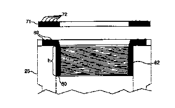
For example, Figure 3 shows the adaptor bushing 60 installed
in an attachment bell 76 of a fitting 78. The bathtub floor 75 is also shown.
Between the underside of the floor 75 and the adaptor bushing rim 66 is
10 provided a rubber gasket 71. Most preferably the gasket 71 includes ridges
72 for better sealing and is compressible to form a good seal. Also shown
is plumber's putty 74 between the fitting 50 and a top surface of the floor 75.
Although Figure 3 illustrates an elbow fitting 78, it will now be appreciated
that the fitting could also easily be a tee-fitting having an identically
15 dimensioned attachment bell as 76.
It will be appreciated that the adaptor bushing rim 66 is formed
with a significant overhang. In this manner enough surface area is provided
on the top side of the rim 66 to allow the rim to be sealed against various
sized main drain openings. Each manufacturer of bathtubs has a slightly
20 different tolerance, so even tubs having the same nominal drain hole will
have variations in practice. What is required is that the rim 66 extend out
from the body enough so that it is sized and shaped to seal around main
drain openings of conventional tubs. Preferably the rim extends more than
twice the wall thickness of the adaptor and most preferably about three times
25 the wall thickness.
Thus the present invention is used as follows. First, the
installer inspects the space under the bathtub to determine what type of
drain connection is to be made. Then the installer will plumb the drain
components together. During this step the installer will insert the adaptor
30 bushing into an appropriate fitting and weld it or otherwise secure it in place.
Then, from inside the bathtub, the cover plate for the overflow drain and the
CA 02209844 1997-07-09
-11-
iift and turn or other drain insert are connected to the plumbing through the
preformed holes in the bathtub. The drain plumbing is essentially clamped
onto the bathtub with the rim sealing around the drain hole, as the drain
fitting is threaded into the adaptor bushing. In this way, the adaptor bushing-
5 fitting combination will be secured to the tub. Then the outlet of the wasteand overflow drain would be connected to the DWV system via a P-trap.
It can also now be appreciated that the mounting rim 66 is
formed on the body of the adaptor bushing 60 in a way that permits the
adaptor bushing to be drawn up tightly onto the underside of the bathtub
10 when the fitting 50 is threaded therein. Thus, the height of the external
surface 62 is sufficient to allow the adaptor bushing 60 to be fully inserted
into the fitting 20 or 26 without any interference from the mounting rim 66.
Most preferably, when the external surface 62 of the adaptor bushing 60 is
fully inserted into the bell of a fitting, the underside of the mounting rim 66
15 will just contact the lip 67 of the end of the bell of the fitting.
It is also preferred to include one or more raised ribs 69 on the
top or outer face of the mounting rim 66 to facilitate the formation of a good
stable grip on the bottom or outer surface of the tub. The ribs 69 can mate
with the gasket 71 ribs to help keep the bell in place. It will also be
20 appreciated that mounting rim 66 should be made strong enough to
accommodated the forces that it becomes subjected to when the fitting 50
is screwed into the adaptor bushing 60 and the combined assembly is
thereby clamped onto the bathtub.
In some cases it may be preferred to use the rubber gasket 71
25 to protect the bathtub from excessive point loading which otherwise may
occur during the action of threading the fitting 50 into the adaptor bushing
60. As will be familiar to those skilled in the art, the bathtub is typically
formed from a porcelain material or the like which while strong and durable
is quite brittle. Thus by placing a rubber or elastomeric gasket, such as
30 shown at 71 with one or more with sealing ribs 72, the porcelain can be
protected. Of course, conventional plumbers' putty 74 can also be used to
CA 02209844 1997-07-09
-12-
provide an adequate seal without the need for over tightening and risking
breaking the ceramic.
It will be appreciated by those skilled in the art that various
modifications and alterations can be made to the present invention without
5 departing from the broad scope of the invention as defined by the appended
claims. Some of these modifications and variations have been discussed
above and others will be apparent. For example, although reference has
been made to a smooth barrel on the outer surface of the adaptor bushing
60, what is really required is that the outer barrel be sized and shaped in a
10 manner that the barrel can be secured into the bell of a standard plastic
plumbing fitting, such as an elbow or a sanitary tee, tee wye, wye and 1/8
bend or the like. Further, while reference has been made to an internal
threaded bore, other interengaging means between the lift and drop drain
fitting 50 and the internal bore of the adaptor fitting 60 could also be used
15 provided that a secure clamping action onto the bottom of the tub around the
drain hole is achieved.