Language selection

Search

Patent 2209885 Summary

Third-party information liability

Some of the information on this Web page has been provided by external sources. The Government of Canada is not responsible for the accuracy, reliability or currency of the information supplied by external sources. Users wishing to rely upon this information should consult directly with the source of the information. Content provided by external sources is not subject to official languages, privacy and accessibility requirements.

Claims and Abstract availability

Any discrepancies in the text and image of the Claims and Abstract are due to differing posting times. Text of the Claims and Abstract are posted:

  • At the time the application is open to public inspection;
  • At the time of issue of the patent (grant).
(12) Patent Application: (11) CA 2209885
(54) English Title: A HAND TOOL HANDLE WITH SHOCK ABSORBENT AIRBAG
(54) French Title: OUTIL A MAIN DOTE D'UN COUSSIN D'AIR AMORTISSEUR DE CHOCS
Status: Deemed Abandoned and Beyond the Period of Reinstatement - Pending Response to Notice of Disregarded Communication
Bibliographic Data
(51) International Patent Classification (IPC):
  • B25G 01/01 (2006.01)
  • B25G 01/12 (2006.01)
(72) Inventors :
  • CHEN, JOHN (Taiwan, Province of China)
(73) Owners :
  • JOHN CHEN
(71) Applicants :
  • JOHN CHEN (Taiwan, Province of China)
(74) Agent: ROBIC AGENCE PI S.E.C./ROBIC IP AGENCY LP
(74) Associate agent:
(45) Issued:
(22) Filed Date: 1997-07-07
(41) Open to Public Inspection: 1999-01-07
Examination requested: 1999-07-06
Availability of licence: N/A
Dedicated to the Public: N/A
(25) Language of filing: English

Patent Cooperation Treaty (PCT): No

(30) Application Priority Data: None

Abstracts

English Abstract


A design of a hand tool handle with shock absorbent
airbag comprising mainly an airbag element within a handle
which is designed to fit insertion of various hand tools,
while the inner hollow space of the handle is designed
for embedding of the airbag so that an airbag is formed
between the handle and the hand tool to absorb shock
from reaction of impacting force and consequently shock
being felt by person holding the hand tool is lowered. The
airbag element can be a hollow structure with two legs
portions, or a cylindrical hollow structure, or even
formed as an inner part of the handle during production.


French Abstract

Outil à main doté d'un coussin d'air amortisseur d'impact. Le coussin d'air est situé dans une poignée et est conçu pour être inséré dans divers outils à main. L'espace intérieur creux de la poignée est conçu pour loger un coussin d'air entre la poignée et l'outil à main afin d'amortir les chocs causés par l'impact et qui sont conséquemment absorbés par la personne qui tient l'outil. Le coussin d'air peut consister en une structure creuse dotée de deux pattes, en une structure cylindrique creuse, ou encore être installé dans la partie intérieure de la poignée pendant la fabrication de l'outil.

Claims

Note: Claims are shown in the official language in which they were submitted.

WHAT IS CLAIMED IS:
1. A hand tool handle with shock absorbent airbag
comprising a handle and an airbag element designed to fit
insertion of various hand tool, in which
- the handle is made of appropriate soft material in
the form of a hollow sleeve corresponding to the shape of
the airbag element so that the airbag element can be
embedded therein through an opening at the rear end of
the handle, while the front end of the handle is formed with
a reception hole having a cross section corresponding to
the cross section of an insertion part of a hand tool;
- the airbag element is a sealed hollow element with
two leg portions and having main hollow body, while its
upper leg and lower leg are connecting to each other and
extended from a side of the main hollow body in a manner
that the upper and lower legs are located on and beneath
the insertion part of the hammer and the main hollow
body is at the end of the handle and embedded therein; and
- the hand tool has an insertion part extended from its
rear end while there is no restriction on the shape of
the insertion part as long as the insertion part can be
retained at the reception hole at the front end of the handle;

whereby the airbag element is first inserted from the
rear end of the handle and entirely placed within the
interior hollow space in the handle so that there is an
air bag between the insertion part of the hand tool and
the handle to absorb shock from reaction of impacting
force which is then transmitted via the air bag and
consequently the shock felt by the person who holds the
hand tool can be significantly lowered.
2. A hand tool handle with shock absorbent airbag as
claimed in Claim 1 wherein the sealed hollow airbag
element has more than two hollow leg portions.
3. A hand tool handle with shock absorbent airbag as claimed
in Claim 1 wherein the a hollow projecting block is formed
on other side of the sealed hollow airbag element and the
rear end of the handle is formed with a small hole so that
the airbag element can be embedded therein while the hollow
projecting block is exposed on the small hole.
4. A hand tool handle with shock absorbent airbag as
claimed in Claim 1 wherein the surface of the handle is
formed with appropriate pattern to provide a considerable
friction to help grasping.
5. A hand tool handle with shock absorbent airbag as

claimed in Claim 1 wherein rear end of the handle has an
annular groove on is inner wall corresponding to an
annular hollow body of the airbag element so that the
annular hollow body is retained by the annular groove.
6. A hand tool handle with shock absorbent airbag as
claimed in Claim 1 wherein the handle and the airbag
element can be formed as an integrated part during their
production.
7. A hand tool handle with shock absorbent airbag as
claimed in Claim 1 wherein the airbag element is an
independent sealed hollow cylindrical airbag with a
reception hole at its center corresponding to the
insertion part of the hand tool and the whole cylindrical
airbag element can be entirely embedded in the hollow
inner wall of a handle so that a hollow annular airbag is
formed between the handle and the insertion part of the
hand tool.
8. A hand tool handle with shock absorbent airbag as
claimed in Claim 7 wherein an end of the cylindrical
airbag element is formed with an annular hollow body and
a hollow projecting block for attaching to the wall at
the rear end of the handle.
9. A hand tool handle with shock absorbent airbag as

11
claimed in Claim 7 wherein the cylindrical airbag element
has a relatively thick wall and is formed with
appropriate pattern on its outer surface to become a
handle with airbag structure.

Description

Note: Descriptions are shown in the official language in which they were submitted.


CA 0220988~ 1997-07-07
A HAND TOOL H~NDLE WITH SHOCX ABSORBENT AIRBAG
BACKGROUND OF THE INVENTION
S (a)Field of the Invention
The present invention relates to a design of a hand tool
handlewithshockabsorbentairbag,particularahandlewithin
an inner airbag so that airbag is formed between the handle
and an insertion part at an end of the hand tool to absorb
shock from reaction of impacting force to moderate the shock
to transmit to the hand tool operator.
(b)Description of the Prior Art
The conventional hand tool, such as hammer, usually has
the rear section of its handle wrapped with a certain soft
rubber or plastic materialto provide a considerable friction
to help grasping, and to provide a somewhat shock absorption
effect to moderate the shock transmitting to the hand tool
user. However, indeed the rubber or plastic wrapped handle
is firmly fitted to the insertion part of the conventional
hand tool, it does provide satisfactory shock absorption
effect though it helps grasping. In other words, the
shock from the reaction of impacting force is directly
transmitted from the hand tool to the handle, the rubber or
plastic material does only provide a very little shock

CA 0220988~ 1997-07-07
absorption effect, which is still far beyond the shock
absorption effect required.
BUMMARY OF THE INVENTION
The main objective of the present invention is to provide
a hand tool handle with shock absorbent airbag which is
designed to fit insertion of various hand tools. The inner
hollow space of the handle is designed for embedding of an
airbag element so that an airbag is formed between the handle
and the hand tool to absorb shock from reaction of impacting
force and consequently shock being felt by person holding the
hand tool is lowered.
Another objective of the present invention is to provide
a design of a hand tool handle with shock absorbent airbag,
in which the airbag element can be a hollow structure with
two legs portions, or a cylindrical hollow structure, or even
formed as an inner part of the handle during production.
BRIEF DEBCRIPTION OF THE DRAWING8
The invention, as well as its many advantages, may be
further understood by the following detailed description and
drawing in which:
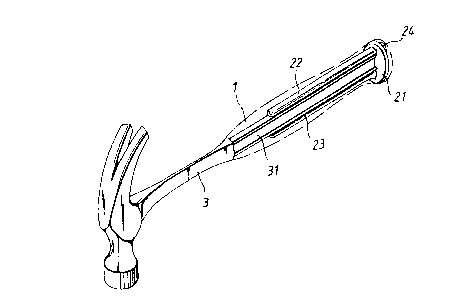
Fig. 1 is a perspective view illustrating an embodiment

CA 0220988~ 1997-07-07
of a hand tool according to the present invention;
Fig. 2 is a fragmented perspective view of the hand tool
with the present invention;
s
Fig. 3 is a cross sectional view of the present invention
without the hand tool;
Fig. 4 is a longitudinal sectional view of the present
invention with the hand tool;
Fig. ~ is a longitudinal sectional view of another
embodiment of the present invention; and
Fig. 6 is a fragmented perspective view of the other
embodiment of the present invention.
DETAILED DESCRIPTION OF THE PREFERRED EMBODIMENTS
As shown in the attached drawings, the hand tool handle
with shock absorbent airbag comprises mainly a handle l and
an airbag element 2. It can be used for any kind of hand tool.
However, in the preferred embodiment described hereinafter
a hammer 3 is applied as an example though indeed there is
no limitation on its application.
The handle l is made of appropriate soft material in the

CA 0220988~ 1997-07-07
form of a hollow sleeve. It surface is designed with an
appropriate pattern 11 to provide a considerable friction
to help grasping. The hollow internal space in the handle 1
is designed with a shape corresponding to the shape of the
airbag element 2 so that the airbag element 2 can be wholly
embedded therein. The front end of the handle 1 is formed
with a reception hole 12 having a cross section
corresponding to the cross section of an insertion part 31
of the hammer or the hand tool to be applied (in the
drawings a H-like cross section is illustrated). A small
hole 13 is formed on the other end of the handle 1 so as
the airbag element 2 can be embedded therein by through
such small hole 13.
The airbag element 2, as illustrated by the preferred
embodiment shown in Figs. 1 thru 4, is a sealed hollow
element with two or more leg portions. It is designed
with a main hollow body 21, an upper leg 22 and a lower
leg 23 are extended from a side of the main hollow body 21,
while its opposite side is formed with a projecting block
24 so that the entire airbag element 2 can be embedded
within the interior space of the handle 1 (as shown in Fig.
3) in a manner that the upper and lower legs 22 and 23
are located on and beneath the insertion part 31 of the
hammer 3 respectively, while the main hollow body 21 is at
the end of the handle 1 and its projecting block 24 is
exposed at the small hole 13 at the end of the handle 1.

CA 0220988~ 1997-07-07
However, the airbag element Z may be designed without such
a projecting block 24. The end of the handle 1 can be
further designed with an annular groove 14 on its inner
wall to retain the main hollow body 21 firmly.
s
The hammer 3, i.e., the hand tool, has an insertion
part 31 extended from its rear end. There is no restriction
on the shape of the insertion part 31, and the hand tool
can be of any kind besides the hammer 3 shown in the
drawings. Therefore, there is no restriction on the shape
of the reception hole 12 at the front end of the handle 1 as
long as it can receive the insertion part 31.
For assembly of the above components, the airbag
element 1 is first inserted from the rear end of the
handle 1 and entirely placed within the interior hollow
space within the handle 1, while its projecting block 24
is exposed on the small hole 13 at the end of the handle 1.
By this way, there is an air bag between the hammer (i.e.,
the hand tool) and the insertion part 31 within the
handle 1 to absorb shock as reaction of impacting force.
The shock is transmitted via the air bag and consequently,
it is moderated so that the shock being felt by the person
who holds the hand tool is significantly lowered.
Figs. 5 and 6 demonstrate another embodiments of the
airbag element according to the present invention. Besides

CA 02209885 1997-07-07
the st~ture illustratèd in the flrst embodiment
described above, the airbàg element 2' can be ah independent
hollow and sealed cylindrical st~ucture. That is, the
airbag element 2l is a hollow cylindrical structure, it has
S a hole 25' with a shape corresponding to the insertion pàrt
31 of the hammer 3 (i.e., the hand tocl), ahd it cah be entirely
embedded within the interior hollow space within the handle
1 so that there is àn annular air bag between the hammer 3
~i.e.~ the hà~d tool3 ahd th~ ins~rti~ pàrt 31 withi~ the
1~ hàndle 1 as shown in Fig. 5 t~ absorb shock from reaction o~
impacting force. Like the flrst embodiment, the rear end of
the cylindrical ai~bag element 2I can be designed with a
circular hollow body 21' and a holl~w projècting block 24'
for being sei~ed to the wall at the rear end of the handle
1.
The description of aforesaid embodiments are intended
to illustrate the means to achieve the objectives of
the present invention, and they should not be applied to
limit the conditions for any embodiment of the present
invention. Many changes and modifications in the above
described embodiment of the invention can, of course, be
carried out without departing from the scope thereof.
For instance, the handle 1 and the airbaq element 2 can be
formed as an integrated part in the production process, or
the wall of the cylindrical airbag element 2' can be
further thickened and formed with any pattern so that it

CA 0220988~ 1997-07-07
itself is a handle for insertion of the insertion part of
the hammer (the handle), or the airbag element is formed
as an interior hollow component during forming of the
handle. Hence, to promote the progress in science and the
S useful arts, the invention is disclosed and is intended
to be limited only by the scope of the appended claims.
Many changes and modifications in the above embodiment
of the invention can, of course, be carried out without
departing from the scope thereof. Accordingly, to promote
the progress in science and the useful arts, the invention
is disclosed and is intended to the limited only by the
scope of the appended claims.

Representative Drawing
A single figure which represents the drawing illustrating the invention.
Administrative Status

2024-08-01:As part of the Next Generation Patents (NGP) transition, the Canadian Patents Database (CPD) now contains a more detailed Event History, which replicates the Event Log of our new back-office solution.

Please note that "Inactive:" events refers to events no longer in use in our new back-office solution.

For a clearer understanding of the status of the application/patent presented on this page, the site Disclaimer , as well as the definitions for Patent , Event History , Maintenance Fee  and Payment History  should be consulted.

Event History

Description Date
Application Not Reinstated by Deadline 2002-07-08
Time Limit for Reversal Expired 2002-07-08
Deemed Abandoned - Failure to Respond to Maintenance Fee Notice 2001-07-09
Letter Sent 1999-07-26
Request for Examination Received 1999-07-06
All Requirements for Examination Determined Compliant 1999-07-06
Request for Examination Requirements Determined Compliant 1999-07-06
Application Published (Open to Public Inspection) 1999-01-07
Classification Modified 1997-10-05
Inactive: First IPC assigned 1997-10-05
Inactive: IPC assigned 1997-10-05
Inactive: Filing certificate - No RFE (English) 1997-09-18
Application Received - Regular National 1997-09-16

Abandonment History

Abandonment Date Reason Reinstatement Date
2001-07-09

Maintenance Fee

The last payment was received on 2000-06-16

Note : If the full payment has not been received on or before the date indicated, a further fee may be required which may be one of the following

  • the reinstatement fee;
  • the late payment fee; or
  • additional fee to reverse deemed expiry.

Patent fees are adjusted on the 1st of January every year. The amounts above are the current amounts if received by December 31 of the current year.
Please refer to the CIPO Patent Fees web page to see all current fee amounts.

Fee History

Fee Type Anniversary Year Due Date Paid Date
Application fee - small 1997-07-07
MF (application, 2nd anniv.) - small 02 1999-07-07 1999-06-28
Request for examination - small 1999-07-06
MF (application, 3rd anniv.) - small 03 2000-07-07 2000-06-16
Owners on Record

Note: Records showing the ownership history in alphabetical order.

Current Owners on Record
JOHN CHEN
Past Owners on Record
None
Past Owners that do not appear in the "Owners on Record" listing will appear in other documentation within the application.
Documents

To view selected files, please enter reCAPTCHA code :


To view images, click a link in the Document Description column. To download the documents, select one or more checkboxes in the first column and then click the "Download Selected in PDF format (Zip Archive)" or the "Download Selected as Single PDF" button.

List of published and non-published patent-specific documents on the CPD .

If you have any difficulty accessing content, you can call the Client Service Centre at 1-866-997-1936 or send them an e-mail at CIPO Client Service Centre.


Document
Description 
Date
(yyyy-mm-dd) 
Number of pages   Size of Image (KB) 
Claims 1997-07-06 4 98
Abstract 1997-07-06 1 18
Description 1997-07-06 7 211
Drawings 1997-07-06 4 60
Representative drawing 1999-01-24 1 8
Filing Certificate (English) 1997-09-17 1 164
Reminder of maintenance fee due 1999-03-08 1 111
Acknowledgement of Request for Examination 1999-07-25 1 193
Courtesy - Abandonment Letter (Maintenance Fee) 2001-08-05 1 182
Fees 1999-06-27 1 30
Fees 2000-06-15 1 30