Note: Descriptions are shown in the official language in which they were submitted.
CA 02210028 2004-06-18
HYDROSTATIC TOOL WITH ELECTRICALLY OPERATED SETTING MECHANISM
1. Fse_Id ,~f the Inven#iQn
This invention relates generally to downhole tools for use in oil or gas
welts and, more particularly, to wellbore annulus pressure-responsive tools
which are actuated by an electrically controlled device.
2. Back4round of the Art
A variety of downhole devices (toots) are utilized in wellbores to facilitate
production of hydrocarbons from subterranean formations. For example,
packers are commonly utilized to seal an annulus between the packer and a
tubular member (typically a wllbore casing? placed within the wellbore.
Producing welibores usually contain formation fluids, such as hydrocarbons
(oil
and or gash and/or connate water. During drilling operations, wellbores
typically
contain drifting fluids (commonly known as the "drilling mud' or 'mud "~
pumped into the wellbore from a surface location. The pressure at a given
depth in the wellbore depends upon the weight of the fluid column above the
depth point. Such a pressure Is referred to as the hydrostatic pressure or
simply the hydrostatic, and it may vary between a few hundred psi to several
thousand psi.
1
CA 02210028 1997-07-09
A variety of downhole tools utilize the hydrostatic pressure to perform
a useful function. The majority of such tools utilize either a mechanical
force
or an explosive charge to actuate a device, which in turn enables the
hydrostatic pressure to act upon a secondary devices to perform an operation
downhole. More recently, electrically operated devices have been utilized in
commercial tools to selectively allow the application of the hydrostatic
pressure
to perform a specific function.
For example, United States Patent No. 5,251,703 to Skinner discloses
a system wherein a solenoid valve in a normally closed position is placed
between the well annulus and a chamber. The chamber has two sections
separated by a power piston. One section communicates with the wellbore via
the solenoid valve and the other section is filled with a working liquid arid
compressed nitrogen to provide back pressure to the first section. When the
solenoid valve is opened, hydrostatic pressure is applied to the first
section,
causing the piston to move, which operated a device coupled thereto. United
States Patent No. 5,251,703 to Skinner discloses three chambers and a
plurality of electrically-operated valves for manipulating the application of
the
hydrostatic pressure to a piston in one of the chambers to cause a device to
operate.
United States Patent No. 5,240,077 to Whitsitt discloses a hydraulic
2
CA 02210028 1997-07-09
setting tool, which is actuated by an electric motor driving a pump. The
Whitsitt device uses a closed hydraulic system to maintain a minimum head
pressure of hydraulic fluid at the pump intake to reduce or eliminate
cavitation,
thus improving the tool viability in high temperature wells.
The present invention provides a relatively simple and reliable downhole
tool wherein the hydrostatic pressure is applied to at least one atmospheric
chamber in the tool by activating a remotely controlled electrically-operated
device. A control circuit in the tool activates the device in response to a
coded
signal transmitted from a remote location, such as the surface.
SUMMARY OF THE INVENTION
The present invention provides a tool for use in wellbores. The
tool is operated by the wellbore hydrostatic pressure. The tool includes one
or
more devices that operate when a mechanical force is applied to such devices.
The tool includes at least one atmospheric chamber. A setting member
disposed in the tool is utilized to provide the mechanical force in response
to
the application of the hydrostatic pressure thereto. Prior to activating the
tool,
the setting member is locked or restrained in an inoperative position. To
operate the device, the tool is placed at a suitable location in the wellbore.
The
atmospheric chamber is charged with the wellbore fluid, which releases the
3
CA 02210028 2004-02-26
setting member from its restrained or locked position, subjecting the setting
member to the weilbore hydrostatic pressure, thereby providing the
mechanical force to operate at least one of the devices. A second
atmospheric chamber may be provided that remains at the atmospheric
pressure, but cooperates with the first chamber as it is charged with the
welibore fluid to operate a second setting member, which operates a second
device. A sensor associated with the tool detects signals transmitted to the
tool from a remote location. A control circuit in the tool receives the
detected
signals from the sensor and in response thereto operates an electrically-
operated flow control device, thereby charging the chamber with the wellbore
fluid.
In accordance with one aspect of the present invention there is
provided a tool for use in a wellbore having a wellbore fluid at a hydrostatic
pressure, comprising:
(a) a device operable by the application of a mechanical force
thereto;
(b) a setting member in communication with the wellbore fluid for
applying the mechanical force to the device, the setting member being
releasably restrained from applying the mechanical force to the device;
(c) a low pressure chamber in the tool for releasing the setting
member when the low pressure chamber is charged with the wellbore fluid;
and
(d) a flow control device operable at a wellbore pressure no greater
than the hydrostatic pressure for selectively charging the low pressure
4
CA 02210028 2004-02-26
chamber with the wellbore fluid to release the setting member from its
restrained position to allow the setting member to apply the mechanical force
to the device.
In accordance with another aspect of the present invention there is
provided an oil field tool for use in a wellbore having a fluid therein at
relatively
high hydrostatic pressure, comprising:
(a) at least two setting devices, each such setting device operable
upon the application of a mechanical force thereto;
(b) at least two setting members, each setting member adapted to
operate an associated one of the at least two setting devices upon the
application of the high hydrostatic pressure to such setting member, each
such setting member releasably restrained prior to the application of the high
hydrostatic pressure thereto for setting its associated setting member;
(c) at least two chambers in the tool, each such chamber at a
relatively low pressure, one of the chambers adapted to be charged with the
wellbore fluid at the relatively high hydrostatic pressure after the tool has
been
conveyed in the wellbore, said chambers cooperating with each other when
one of the chambers is charged with the wellbore fluid to release the setting
members from their respective restrained positions, subjecting the setting
members to the relatively high hydrostatic pressure, thereby causing each of
the setting members to operate its associated setting device; and
(d) a flow control device between the wellbore fluid and the
chamber adapted to be charged with the wellbore fluid, said flow control
device being operable at a wellbore pressure no greater than the hydrostatic
pressure for controlling the wellbore fluid flow into such chamber.
4a
CA 02210028 2004-02-26
In accordance with another aspect of the present invention there
is provided a tool for use in a wellbore having a fluid therein at relatively
high
hydrostatic pressure, comprising:
(a) an elongated tool body having a bore therethrough;
(b) a first device and a second device, each such device adapted to
be operated upon the application of a mechanical force to perform a function
in the wellbore;
(c) a first setting member movable from a first position to a second
position by the high hydrostatic pressure, said first setting member adapted
to
generate the mechanical force to operate the first device in the wellbore when
the first setting member is moved to the second position, said first setting
member being restrained in the first position prior to conveying the tool in
the
wellbore;
(d) a second setting member movable from a first position to a
second position by the hydrostatic pressure, said second setting member
adapted to generate the mechanical force to operate the second device in the
wellbore when the second setting member is moved to the second position,
said second setting member being restrained in the first position prior to
conveying the tool in the wellbore;
(e) a first chamber and a second chamber, each such chamber at
an initial relatively low pressure, the first chamber adapted to receive the
wellbore fluid and the second chamber adapted to remain at the relatively low
pressure, said first and second chambers cooperating with each other upon
the receipt of the wellbore fluid into the first chamber to release the first
4b
CA 02210028 2004-02-26
setting member and the second setting member from their respective first
positions, thereby enabling the relatively high hydrostatic pressure to move
the first and second setting members to their respective second positions,
thereby generating sufficient mechanical force to set their associated
devices;
(f) a fluid communication path between the wellbore fluid and the
first chamber;
(g) a flow control device in the fluid communication path and
operable at a wellbore pressure no greater than the hydrostatic pressure for
selectively enabling the communication of the wellbore fluid into the first
chamber;
(h) a sensor associated with the tool for detecting command signals
transmitted to the tool; and
(i) a control circuit in the tool for selectively operating the flow
control device in response to the signals detected by the sensor.
In accordance with yet another aspect of the present invention there is
provided a downhole tool for use in a wellbore containing wellbore fluid at a
hydrostatic pressure, said downhole tool comprising:
(a) a device adapted to operate upon the application of a
mechanical force;
(b) a movable member in communication with the wellbore fluid
pressure for applying the mechanical force to the device, said movable
member being held in a restrained position that prevents the application of
the
mechanical force to the device;
4c
CA 02210028 2004-02-26
(c) a low pressure chamber adapted to be in fluid communication
with the wellbore fluid, said chamber having an associated restraining
member preventing the movable member from applying the mechanical force
to the device until the wellbore fluid is supplied to the low pressure
chamber;
and
(d) an electrically-operated device operable at a wellbore pressure
no greater than the hydrostatic pressure, said electrically-operated device in
one operating position allowing the wellbore fluid at the hydrostatic pressure
to be supplied to the low pressure chamber to cause the restraining member
to release the movable member from the restrained position, thereby allowing
the movable member to apply the mechanical force to the device.
In accordance with still yet another aspect of the present invention
there is provided a downhole tool for use in a wellbore containing a wellbore
fluid at a hydrostatic pressure, said downhole tool comprising:
(a) a device operable in the wellbore upon the application of a
mechanical force thereto;
(b) a movable member in communication with the wellbore fluid at
the hydrostatic pressure for applying the mechanical force to the device;
(c) a restraining assembly in the tool restraining the movable
member from applying the mechanical force to the device until the restraining
assembly is acted upon by the wellbore fluid; and
(d) an electrically-operated device operating at a wellbore pressure
no greater than the hydrostatic pressure, said electrically-operated device in
a
normal operating position preventing the wellbore fluid from acting on the
4d
CA 02210028 2004-02-26
restraining assembly and upon activation allowing the wellbore fluid to act on
the restraining assembly, allowing the movable member to release from the
restrained position and apply the mechanical force to the device.
Examples of the more important features of the invention have been
summarized rather broadly in order that the detailed description thereof that
follows may be better understood, and in order that the contributions to the
art
may be appreciated. There are, of course, additional features of the invention
that will be described hereinafter and which will form the subject of the
claims
appended hereto.
BRIEF DESCRIPTION OF THE DRAWINGS
For detailed understanding of the present invention, references should
be made to the following detailed description of the preferred embodiment,
take
4e
CA 02210028 1997-07-09
in conjunction with the accompanying drawings, in which like elements have
been given like numerals, and wherein:
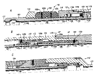
FIG. 1A-1C show a longitudinal partial cross-sectional view of a
downhole tool according to the present invention, in its normal closed
position.
FIGS. 2A-2C show a longitudinal partial cross-sectional view of the
downhole tool shown in FIGS. 1A-1C after the tool has been set by applying
the hydrostatic pressure upon the activation of the electrically-
operateddevice.
FIGS. 3A-3C show a longitudinal partial cross-sectional view of the
downhole tool shown in FIGS. 1A-1C after the tool has been set by applying
the hydrostatic pressure upon the activation of a secondary mechanical means.
FIG. 4 shows a schematic diagram of a cased wellbore with the tool of
FIG. 1A-1C set in the wellbore and associated control units for communicating
command signals to the tool after it has been conveyed to the location where
the tool will be set.
5
CA 02210028 1997-07-09
DETAILED DESCRIPTION OF PREFERRED EMBODIMENTS
FIGS. 1A-1C show a partial cross-sectional view of an embodiment of
a downhole hydrostatic tool 100 in its normally closed position, i.e., prior
to
setting of the tool in a wellbore according to the present invention. FIGS. 2A-
2C show a partial cross-sectional view of the tool shown in FIGS. 1A-1C after
it has been set by activating an electrically-operated device. FIGS. 3A-3C
show
a partial cross-sectional view of the tool shown in FIGS. 1A-1C after it has
been set by activating a secondary mechanical means. In these figures, the
tool 100 is shown to contain a packing element system 102 having a plurality
of individual packing elements 102a-c and an anchor or slip 104 as examples
of the type of devices that may be set in a wellbore by the wellbore
hydrostatic
pressure according to the present invention. The application of the present
invention, however, is not limited to such devices. Any other suitable device
may be set by utilizing the concept of the present invention.
Referring to FIGS. 1A-1C and FIGS. 2A-2C, the tool 100 is substantially
tubular having an interior surface 106 defining an internal axial bore through
the
tool or a through passage 108 for allowing the passage of fluids or other
devices through the tool 100. The tool 100 has a suitable profile 110 at an
upper end 111 that enables the tool to attach or couple to another device or
an
element, such as a tubing. The tool 100 terminates with a lower profile 112
6
CA 02210028 1997-07-09
at a lower end 113, for attachment to a desired element. The packing element
system 102 is disposed between a fixed member 114 and a movable setting
subassembly (also referred herein as the setting sub or setting member) 116.
The packing element system 102 contains one or more individual packing
members, such as members 102a-c. The packing members expand, radially
outward when the setting sub 116 is urged against the packing element system
102, which causes the packing elements 102a-c to seal against the interior of
a wellbore, typically a casing (not shown).
The tool 100 is shown to contain three atmospheric chambers. The first
atmospheric chamber 120 is defined in the tool body 101 adjacent to the
setting sub 116 along the downhole or lower side of the tool between the tool
interior 106 and a slidable outer housing 170, the functions and operation of
which housing are described later. The first atmospheric chamber 120 may be
selectively placed in fluid communication with the fluid surrounding the tool
(the wellbore fluid when the tool 100 is placed in the wellbore) by an
electrically-operated device 130. The device 130 is preferably disposed within
the setting sub 116 to control the flow of the wellbore fluid to the first
chamber 120 from a fluid inlet or port 132 to a fluid passage 134. The device
130 acts as a fluid control valve. In a preferred embodiment, the device 130
contains a piston 138 that is held in a closed position that prevents the flow
of any fluid from the port 132 to the passage 134, and hence the first
7
CA 02210028 2003-03-19
atmospheric chamber 120. The device 130 is preferably a solenoid-type
device, which moves the piston 138 to the right or the open position when
electrical energy is applied to the device 130, allowing the wellbore fluid to
flood the first atmospheric chamber 120. The fluid control device 130 remains
closed at all other times. Alternatively, the fluid control device 130 may be
operated by a motor (not shown) or by any other suitable electrically-operated
device.
An electronic control circuit 137, preferably placed in the first
atmospheric chamber 120, controls the operation of the device 130. A sensor
139 associated with the tool 100 detects signals transmitted from a remote
location, such as the surface, and transmits the detected signals to the
control
circuit 137. In one embodiment, the sensor may be a strain gauge securely
attached to the body 101 and the signals transmitted from the surface may be
in the form of pulses induced into the wellbore fluid at a desired frequency.
The sensor 139 communicates the detected signals to the electronic control
circuit 137. The tool 100 is preferable assigned an address, which is stored
in
a downhole memory associated with the tool 100. The electronic control
circuit 137 decodes the signals received from the sensor 139 and, if the
signals match the unique tool address, it causes the electrical energy from a
power pack 141 to be applied to an electrically-operated device 130, such as
a solenoid or a motor 130. When the device 120 is activated by the device
130, the piston 138 moves to the right, opening fluid communication between
the
8
CA 02210028 1997-07-09
wellbore fluid and the first atmospheric chamber 120, as described in more
detail later.
A second atmospheric chamber 122 is formed between a retaining sleeve
140 and the tool interior 106. A movable locking sleeve 142 is disposed
between the first and second atmospheric chambers to prevent any fluid
communication between these chambers. A seal 143 formed in the member
140 and the body 101 provides the fluid seal between the two chambers. The
locking sleeve has a seat 142a which holds a locking member 144 in place. In
this position, the locking member 144 restrains the outer housing from moving
due to the presence of the hydrostatic pressure being applied to the outer
housing. The locking member 142 has a reduced dimension 142b between the
seat 142a and the seal 143. If the locking member 142 is moved to the right
(downward), the seat moves from under the locking member 144, releasing the
locking member and, thus, the outer housing from its initial restrained
position
and the reduced dimension 142b moves inside the seal 143, thereby allowing
the fluid to pass from the first chamber 120 to the second chamber 122. If the
locking member 142 is moved a sufficient distance to the left (upward), the
locking sleeve moves out of the seal 143, thereby allowing the fluid to pass
from the first chamber 120 to the second chamber 122. Thus, these two
chambers and the locking sleeve 142 cooperate to prevent any fluid
communication between the first atmospheric chamber 120 and the second
9
CA 02210028 1997-07-09
atmospheric chamber 122, as long as the flow control device 130 remains in
the closed position, as shown in F1G. 1A. A setting piston 150 is disposed
between the atmospheric chamber 122 and a third atmospheric chamber 155,
which always remains at a relatively low pressure during operation of the tool
100.
A slip ring 180 is disposed around the tool 100 between the housing 170
and the anchor 104 setting the anchor when the slip ring 180 is subjected to
the wellbore hydrostatic pressure. The outer housing 170 is specialty profiled
around the setting sub 116, the retaining sleeve 140, the various atmospheric
chambers and the slip ring 180. An upper end 170a of the outer housing 170
abuts an edge 116a formed by a reduced outer dimension of the setting sub
116. An end 170b, formed by a reduced dimension of the housing 170, abufs
against an upper end 180a of the slip ring 180. The lower end 170c of the
outer housing 170 retains a retainer member or dog 182 between the slip 180
and the setting piston 150.
The operation of the tool 100 will now be described, while referring to
FIGS. 1A-1C and FIGS. 2A-2C. To set the tool 100 in a wellbore, it is
conveyed into a wellbore and positioned at the desired place. The tool 100
may be conveyed by any suitable method, such as by a tubing or a wireline.
The tool 100 in the wellbore is surrounded by the wellbore fluid, which is at
a
CA 02210028 1997-07-09
relatively high pressure ( referred herein as the "hydrostatic pressure").
When
the tool 100 is in the wellbore, the areas of the tool 100 denoted by HP in
FIGS. 1A-1C are at the hydrostatic pressure, as such areas are in fluid
communication with the wellbore fluid. Each of the atmospheric chambers
120, 122 and 155, however, remains at their respective initial pressures
(atmospheric pressure), except for minor changes due to change in the
temperature from the surface to the wellbore depth, where the tool is placed.
The tool 100 at this stage is inoperative. In this inoperative mode, the
locking sleeve 142 remains stationary as the pressure in both the first
chamber
120 and the second chamber 122 is the same. The seal 143 prevents any
movement of the locking sleeve 142 into the second chamber 122. The
locking member 144 is held in place by the locking sleeve 142, which prevents
the outer housing 170 from moving toward the setting sub 116, even though
the outer housing is under the hydrostatic pressure. The slip ring 180
prevents
the outer housing 170 from moving it to the right, i.e., toward the slip 104.
The slip ring 180 remains stationary, as the retaining member 182 prevents
any movement of the slip ring 180 to the right. The setting piston 155 remains
in its initial position between the second chamber 122 and the third chamber
155 as the retaining member 182 remains locked in its position between the
outer housing 170 and the pin 164. Seals 156a and 156b around the setting
piston 155 provide hydraulic seals that prevent flow of any fluid into the
third
11
CA 02210028 1997-07-09
chamber 155, which as noted earlier, remains at the low pressure. Thus, in the
nonoperative mode, the devices, such as the packing element system 102 and
the anchor 104, remain in their respective retracted positions, as shown in
FIGS. 1 A-1 C.
After the tool 100 has been positioned at the desired location within the
wellbore, it is ready to be set in the wellbore. Once the control circuit 139
receives the command or actuation signal from the surface, it causes power
from the downhole power pack 141 to be sent to the device 135, v~rhich
actuates the flow control device 130, causing the wellbore fluid to flood the
first chamber 120. The flooding of the first chamber 120 causes the pressure
in the first chamber 120 to suddenly rise to the hydrostatic pressure,
creating
a differential pressure between the first chamber 120 and the second chamber
122, which is still at the initial low pressure. This pressure differential
acts
across the o-rings 143 around the locking sleeve 142, shifting the locking
sleeve 142 to the right (downhole). Shifting of the locking sleeve 142
releases
the locking member 144, releasing the outer housing from the initial locked
position and allowing the fluid from the first chamber 120 to flood the second
chamber 122. _
Releasing the locking member 144 frees the outer housing 170 from its
initial locked position. The hydrostatic pressure acting on the outer sleeve
170
12
CA 02210028 2003-03-19
moves it to the left (upward), causing the upper end 170a to urge against the
reduced end 116a of the setting sub 116, which in turn urges the setting
element system 102, causing the setting elements 102a-c to expand radially
outward as shown by numeral 103, setting the element system in the
wellbore. Once the outer housing 170 has moved a sufficient distance
upward, it uncovers the retaining element (retainer dog) 164, leaving the
setting piston 150 free to move downward. The hydrostatic pressure in the
second chamber 122 acts on the setting piston 150, causing it to move to the
right (downward), closing the third chamber 155 from below. The third
chamber, however remains at a relatively low pressure, since it remains
isolated from the hydrostatic pressure. As the setting piston 150 moves to the
right (downward), it urges the slip ring 180 toward the anchor 104, causing
the
anchor to expand radially outward, thereby setting the anchor teeth 105 in the
wellbore casing.
Thus, in the embodiment of the invention shown in FIGS. 1A-1C and
described above, all of the chambers (chambers 120, 122 and 155) are
initially at a relatively low pressure (typically atmospheric pressure). The
chambers cooperate with each other to release the setting members from
their initial restrained or locked positions, allowing the hydrostatic
pressure to
move these setting members to their respective second positions. Each of
the setting members provides the desired mechanical force to its associated
device in the second position, thereby operating its associated devices,
The above-described electrically-operated setting mechanism is the
primary or preferred setting mechanism. The present invention provides a
13
CA 02210028 2003-03-19
secondary mechanical method for operating the devices 102 and 104 if the
primary mechanism fails to operate after the tool has been set in position in
the wellbore. The operation of the secondary mechanism will now be
described while referring to FIGS. 3A-3C. A punch hole 190 is formed in the
body 101 that may be punched from within the interior 108 of the tool 100.
The punch hole 190 is positioned such that when the hole is punched, it will
enable the wellbore fluid from the interior 108 to flood the second
atmospheric
chamber 122. The flooding of the second chamber will causes the hydrostatic
pressure to act on the o-rings 143 of the locking sleeve 142, shifting the
locking sleeve 142 to the left (upward), unlocking the locking member 144.
The remaining operation of the various elements for setting the elements 102
and 104 is the same as described above in reference to FIGS. 1 A-1 C and
FIGS. 2A-2C.
FIG. 4 shows a schematic elevational diagram of a system for setting
the tool 100 in the wellbore 210. The wellbore 210 is shown lined with a
casing 214. The tool 100 is conveyed into the wellbore 210 through a
wellhead equipment 220 by a suitable means, such as a tubing 222. A control
unit 240 at the surface causes a pulsar 245 to induce pressure pulses at a
predetermined frequency corresponding to the address stored in the toot 100.
The pulses are transmitted downhole via the wellbore fluid 250. As described
earlier, the sensor 139 detects the pulses, and transmits corresponding
signals to the control circuit 137 in the tool 100. The control circuit 137
then
causes the device 130 (see FIG. 1A) to operate as described earlier, thereby
operating the devices 102 and 104. It should be noted that any suitable
14
CA 02210028 2003-03-19
apparatus and method may be used to activate the tool.
The present invention contemplates the use of one or more of the
apparatuses and methods for generating and receiving the signals described
in United States Patents 5,226,494 and 5,343,963. The present invention,
however, may utilize any other suitable means for communicating command
signals to the control circuit 137 in the tool 100. For example, the command
signals may be transmitted from a remote location by a magnetic device,
direct transmission of signals over a data link or any other suitable means.
Appropriate sensors corresponding to these devices will then be placed in the
tool to detect the transmitted signals. In majority of the applications for
the
device of the present invention, a one way communication from the surface to
the downhole control circuit 137 is sufficient. The system shown FIG. 4 may
utilize a two-way telemetry. in that case, the downhole control circuit is
designed to contain electronic circuitry that is adapted for two-way
communication.
CA 02210028 1997-07-09
While the foregoing disclosure is directed to the preferred embodiments
of the invention, various modifications will be apparent to those skilled in
the
art. It is intended that all variations within the scope and spirit of the
appended
claims be embraced by the foregoing disclosure.
16