Note: Descriptions are shown in the official language in which they were submitted.
CA 02210175 2003-O1-07
' GENERATOR SOUND SHIELD
Back~ound of the Invent~o,L-~
This invention relates to a sound shield fox a
generator, and particularly to a shield in the form of a box
or container which can be constructed from corner connectors
to connect top and side rails with the rails providing
attachment of panels.
Electric generators axe by their nature noisy as they
are powered by an internal combustion engine. It is
therefore desirable to have a sound shield which can enclose
the engine and generator. It is further desirable to have
such a sound shield Which can be constructed with few
component parts which also afford versatility in the size of
the shield, as well as its manner of construction.
Corner connectors for assembling panel sections are
well known. These are shown in U_S. patent 4,928,470 and
4,747,248. The use of pins and apertures to assembly
housing members is illustrated in U.S. patent 4,914,929.
However, the prior art does not disclose an easily assembled
enclosure which can be assembled in close quarters.
MKE~402~743.01
CA 02210175 2003-O1-07
-2
Summary of the Invention
The present invention provides for an acoustical enclosure for an acoustical
enclosure for an engine generator set comprising: a plurality of rail members
constructed and arranged when assembled to form a frame for an enclosure, said
rail members having notches in the ends thereof; a plurality of connector
members,
at least some of the connector members having at least three sides for
interconnecting ends of three of the rail members to form the frame; connector
pin
members extending from at least three sides of some of the connector members
for
engaging the notches of the rail members in a manner to provide a slide-
together
connection and a slide-apart disconnection; and a plurality of panel members
connected to the rail members to provide the enclosure; whereby the acoustical
enclosure can be easily assembled and disassembled in close quarters.
The acoustical sound can be used for Marine, Standby, Prime and Mobile
applications. It has initially been designed for the marine generator market.
The
unique design concept is its expansibility to allow easy change in size with
no
change in tooling. In its most basic sound shield form it is a rectangular
box. It is
constructed using four outside molded plastic or cast aluminum corner
connectors.
Four extruded or molded top rail members are connected by the connector
members
and four side rail members need only be square cut to the proper length and
pushed
on to three of the nine drive pins in the corner connector members. The
assembled
rail members will then enclose a rectangular frame box with a top opening and
four
CA 02210175 2003-O1-07
side openings. In its most common construction the bottom
of the frame side rail members wi~l7, be mounted and affixed
to generator skid rails. When connected to a generator set
skid rail, a sound shield frame will have five openings that
can have panel members installed. The side panel members
can be of any adequate material such as aluminum, steel,
plastic, fiberglass or any material that can be formed into
a structurally rigid sound absorbing panel.
In a preferred embodiment, the generator sound shield
l0 has six outer connector members and two inner connector
members to provide connection for thirteen rail members and
seven panel members.
Brief Description of the Drawings
Fig. 1 is a front view in elevation of the generator
sound shield in accordance with the invention;
Fig. 2 is a top plan view of the generator sound
shield;
Figs. 3 and 4 are opposing end views thereof;
Figs. 5 is a cop view of one of the connectors employed
in conjunction with the generator sound shield shown in
Figs. 1-4;
Fig. 6 is a side view of the connector shown in Fig. 5;
Fig. 7 is a sectional view taken along line 7-7 of Fig.
s;
Fig. a is a sectional view taken along line 8-8 of Fig.
6;
Fig. 9 is a side view of the connector shown in Fig. 5;
-3-
MKE\d023~a3-01
CA 02210175 2003-O1-07
Fig. 10 is a bottom view of the connector shown in Fig.
5;
Fig. 11 is a side view of another connector employed in
conjunction with the generator sound shield shown in Figs.
1-4;
Fig. 12 is a top view of the connector shown in Fig.
11;
Fig. 13 is a sectional view taken along line 13-13 of
Fig. 12;
Fig. 14 is an end view of the connector shown in Fig.
1l;
Fig. 15 is a view similar to Fig. 12 of an opposing
side;
Fig. 16 is a bottom view of the connector shown in Fig.
16;
Figs. 17, 1s, 19, 20 and 21 axe side views of rail
members employed in conjunction with the generator sound
shield shown in Figs. 1-4;
Figs. 17A, 18A, 8 and C. 19A, 20A and 21A, B and C are
cross-sectional and partial employed views of the respective
rail members shown in Figs. 17-21;
Fig. 22 is a side view in partial section illustrating
the connection of rail members to the connector shown in
Figs. 5-10; and
Fig. 23 is a side view illustrating the connection of
rail members to the connector shown in Figs. 11-16.
-4-
HKi\4033743.01
CA 02210175 2003-O1-07
pescription of the Preferred embodiment
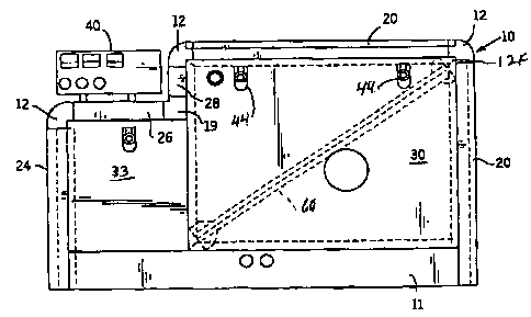
Referring to Figs. 1-4, the generator sound shield,
generally 10, is shown in conjunction with a skid rail 11.
The generator sound shield 10 is composed of six outer
corner connector members 12. These corner connector members
12 connect with the rail members 20, 22, 24, 26 and 28.
There are also two inner corner connector members 19 which
connect With the rail members 26 and 28. These rail members
provide attachment with the front panel member 30, a top
l0 panel member 32 and the end panel member 38, as well as
smaller front panel 33, end panels 36 and 34 and top panel
member 37. A control console 40 for a housed generator set
is positioned on panel member 3~. In addition, back panels
(not shown) similar to panels 30 and 33 are also provided to
I5 form a box-like enclosure for a marine generator which is
powered by an internal combustible engine which are not
shown.
Referring to Figs. 5-10, there is illustrated the outer
connector member 12. As indicated in these Figures, the
20 outer Connector member 12 has nine locating pins 22A. Three
locating pins 12A extend from each of the three faces of the
connector member 12. The same pertains to the inner
connector member 19 shown in Figs. 11-16 also having three
locating pins 19A extending from each of the two faces.
25 These locating pins fit into the notches of the respective
rail members. Fox example, there is shown in Figs. 18, 18A-
18C, rail member 24 with notches 24A, B and C which would
receive three of the locating pins 1.2A extending from
-5-
14XE~10137a3.01
CA 02210175 2003-O1-07
connector member 12. Rail member 24 provides two of shorter
end rails. In a similar manner, three of the locating pins
12A will be received in the notches 22A, B and C of the rail
22 which provides the top rail members. The remaining three
pins 12A are received in the notches 26A, B and C of rail
member 26. The remaining rail members 2o and 28 are
connected to the connector members 12 in a similar three
directional manner.
Concerning connectors 19, they also have three locator
pins 19A extending from the sides thereof. However, they
extend from only two sides to make connections with rail
members 26 and 28 with the locator pins 19A extending into
the notches 26A, B and C and 28A, B and C.
It is seen that the horizontal rail members 22 and the
vertical corner rail members 20 and 24 are of different
lengths. This provides an enclosure of different heights,
widths and lengths.
Figs. 22 and 23 illustrate the connections between the
rail members after they are positioned by the locator pins
12A and 19A of connector members 12 and 19. As shown in
Fig. 22, a bracket 46 connects rail members 20 and 28 with
pop rivets 47 providing a secure connection. Likewise in
Fig. 23, a bracket 49 connects rail members 28 and 26 also
with pop rivets 47.
It is seen in conjunction with the drawing Figures 17A,
18A, 19A, 20A and 21A that there are the flange members for
the rail members such as shown at 22D and 22E in conjunction
with Fig. 21A. These will receive portions of the panel
members for support at the ends thereof. For example, in
-6-
Hxs\so~a~ea.oi
CA 02210175 2003-O1-07
conjunction with rail member 22, the flange 22E will receive
a top portion of end panel 38, whereas the flange 22D will
have a portion of top panel 32 resting thereon. In a
similar manner, the rail members 20 will have the flange 20E
receive the front panel 30 and the flange 20D provide a
support surface for the top panel 32.
Referring back to Figs. 5-16, it is seen that there are
also flange members extending from connector members 12 and
19. These are indicated at 12C, 12D and 12E for connector
member 12 and afford contact with the panel members in three
different planes. They are aligned with the flanges of the
rail members and provide, in conjunction with the body
members of the connector members, pockets 12F and 12G for
the corners of the panels such as 30 and 32, as seen in
Figs. 1 and 2. Concerning connector member 19, there are
flange members 51 and 52 for abutment with panels 33 and 30
and a right angled flange member 55 for support of the
opposing ends of top panel 37.
The side panels, such as 30, 34, 38, 20 and 33, are
attached to the rail members such as by the latches at 44.
These are available as part No. CS-11-36 from Southco., Inc.
of Concordville, PA. Braces such as 60 can also be provided
for the panels such as for panels 30, 32 and 38.
While the panels are preferably secured by the latches.
they can also be held in place with a screw or pop rivet.
These panels can be formed from prepainted aluminum, steel,
plastic, fiberglass or any other suitable material capable
of structurally holding sound insulating materials. The
sound insulating materials can be sprayed foam, flat sheets
_7_
Mite\1023713 . O1
CA 02210175 2003-O1-07
or pressure sensitive adhesive or loose fiberglass bats held
by braces. The completed sound shield then can be assembled
on the skid 17, or dropped over a generator set as a
completed sound housing construction. with the prepainted
panels and access doors added to the assembled frame, the
sound housing is complete.
A highly attractive and pleasing appearance is provided
for the generator sound shield l0 from xounded corner
connector members and rail members. Rail profiles can have
many end profiles to allow creating a pleasing appearance.
This is seen in conjunction with Figs. 17A and 18A wherein
the rail members 20 arid 24 are formed from body members 20F
and 24F having an essentially C-shape with two respective
slightly curved portions 20G, 20H and 24G, 24H of different
lengths joined together. There are two respective straight
portions 20I, 20J and 24I, 24J extending from opposing ends
thereof with two flange portions 20D, 20E and 24D, 24E
extending from the two straight portions.
Corner connector members can have several shapes to
match the rail member profile to allow creating a pleasing
appearance. Infinitely variable sound housing sizes are
afforded by cutting the rail members to any desired length,
Standardized corner connector members can be molded from
plastic or cast from aluminum. Many varying combined
rectangular sound housing shapes and sizes are possible from
the combination of an inside and outside corner connector
member design.
_g_
NKE~40Z3713.0I
CA 02210175 2003-O1-07
The use of smooth surfaced locating pins 12A and I9A
affords a construction that can, if necessary, be easily
assembled in a ship's engine room or taken apart for
service. Connector pins with smooth diameters that are a
S tight slip fit into the rail member notches, and the
attachment of the rails with brackets and pop rivets allow a
sound housing construction that can be easily disassembled
by drilling out the rivets. In most instances, it is not
necessary to take the frame apart as the required access can
1o be effected by removal of the top panel 32. Where
additional access is required, a take apart sound housing
construction is very convenient for marine, standby, prime
power applications that are in tight quarters. The knock
down convenience of the sound housing means a large housing
15 can be used that would not normally fit through a small
access opening. The thin flat panels, skinny rails and
small corner connectors can be taken into the cramped
quarters separately and assembled over the generator chat is
already in place. All the panels including the top can have
2o latches which will allow easy and complete service access.
Rail members can be extruded from aluminum in long
lengths and cut off to the required length which makes them
inexpensive and no tooling cost. Corner connector members
can be molded from plastic which makes them low cost.
2S Plastic rails could also be employed, and corner connectors
could be made from colored plastic, this allows the color to
remain even if the surface is scratched or gouged. Flat
side panels are easily manufactured from prepainted sheet
aluminum, sheet steel, sheet plastic and or sheet fiber
-9-
HK6\4073753.01
CA 02210175 2003-O1-07
glass. The flat quality of the sheet material used for the
side panels allows access holes to the sound housing
interior to be easily manufactured and easily covered with
flat matching panel shapes. Flat panels are easily sound
attenuated with flat sound insulation attached with pressure
sensitive adhesive. The sound housing can be a drop over
design, which means it can be assembled away from the
generator set and installed by dropping over it at a later
time. The 'sounding housing can also be assembled around the
generator set which can allow a smaller housing outside
dimension which may be valuable in tight quarters_ The
rectangular frame configuration allows for standardization
of the rail members and the corner connector shape. Sloped
or slanted side panels although more attractive do not allow
optimum part simplification and minimum part count.
Another important advantage of the invention is seen in
requiring only two versions of the connector members 12 and
l9 to form the complete enclosure.
Further, the rail/frame construction allows all
vertical removal of side and end panels to be access points.
Thi$ means maintenance service is simplified as access is
offered from all four sides. In addition, the top panels
can also be removed for service purposes.
While the generator sound shield has been shown in
conjunction with a marine generator, it can also be employed
with other portable machinery which has a tendency to create
noise.
-lo-
MK8~IO237a3.01