Language selection

Search

Patent 2210359 Summary

Third-party information liability

Some of the information on this Web page has been provided by external sources. The Government of Canada is not responsible for the accuracy, reliability or currency of the information supplied by external sources. Users wishing to rely upon this information should consult directly with the source of the information. Content provided by external sources is not subject to official languages, privacy and accessibility requirements.

Claims and Abstract availability

Any discrepancies in the text and image of the Claims and Abstract are due to differing posting times. Text of the Claims and Abstract are posted:

  • At the time the application is open to public inspection;
  • At the time of issue of the patent (grant).
(12) Patent: (11) CA 2210359
(54) English Title: WIRING DEVICE WITH GROUND CLAMPING PLATE
(54) French Title: DISPOSITIF DE CABLAGE A PINCE DE MISE A LA TERRE
Status: Expired and beyond the Period of Reversal
Bibliographic Data
(51) International Patent Classification (IPC):
  • H01R 09/18 (2006.01)
  • H01H 09/12 (2006.01)
(72) Inventors :
  • OSTERBROCK, JAMES A. (United States of America)
  • BRYNDZIA, MICHAEL R. (United States of America)
(73) Owners :
  • PASS & SEYMOUR, INC.
(71) Applicants :
  • PASS & SEYMOUR, INC. (United States of America)
(74) Agent: KIRBY EADES GALE BAKER
(74) Associate agent:
(45) Issued: 2000-09-05
(22) Filed Date: 1997-07-15
(41) Open to Public Inspection: 1998-04-09
Examination requested: 1997-07-15
Availability of licence: N/A
Dedicated to the Public: N/A
(25) Language of filing: English

Patent Cooperation Treaty (PCT): No

(30) Application Priority Data:
Application No. Country/Territory Date
731,086 (United States of America) 1996-10-09

Abstracts

English Abstract


The present invention relates to electrical wiring devices such as
electrical receptacles, switches, and the like, and more particularly to wiring
devices with a clamp for the ground connections to such devices. The present
invention includes a pressure plate which engages the ground plate of a
receptacle with legs of a pressure plate disposed within correspondingly
shaped recesses adjacent the ground plate of the receptacle, so that the
pressure plate is substantially constrained from rotation relative to the groundplate so that a wire can be received between the ground plate and the pressure
plate when the screw is backed out a sufficient distance.


French Abstract

Cette invention concerne des dispositifs de câblage électrique tels que prises, commutateurs et appareils analogues et, plus particulièrement, des dispositifs comportant une pince de mise à la terre. La présente invention comporte une plaque de serage qui s'appuie sur le plot de mise à la terre de la prise. Cette plaque comporte des pattes qui s'engagent dans des évidements ménagés à proximité du plot susmentionné et l'empêchent quasi totalement de tourner par rapport audit plot. Ce montage permet d'insérer un conducteur de mise à la terre entre ladite plaque et ledit plot dès que la vis de pression est suffisamment dévissée.

Claims

Note: Claims are shown in the official language in which they were submitted.

I Claim:
1. A wiring device comprising:
(a) a ground plate to which a ground connection is to be made;
(b) a threaded opening in the ground plate;
(c) a screw engaged with the threaded opening and having an
enlarged head;
(d) a pressure plate having an opening therethrough and
engaging the screw between the enlarged head and the ground plate; and
(e) a recess on one of the ground plate and the pressure plate
and a corresponding leg on the other of the ground plate and the pressure plate
for substantially preventing rotation of the pressure plate relative to the
ground plate when the screw is engaged with the pressure plate.
2. The wiring device as defined in Claim 1 in which the pressure plate
includes a bull nose for guiding a wire attached to the wiring device into a
fixed location relative to the pressure plate.
3. The wiring device as defined in Claim 1 in which the pressure plate
includes a cut-away region for substantially preventing two wires from being
simultaneously engaged by the pressure plate, one on each side of the screw.
4. The wiring device as defined in Claim 1 in which the screw includes
a deformed end opposite the enlarged head for preventing the screw from
being withdrawn from the threaded opening, while still permitting the screw
to be turned.
5. The wiring device as defined in Claim 1 in which the recess is on
the ground plate and the corresponding leg is on the pressure plate.
6. The wiring device as defined in Claim 1 in which the ground plate,
the screw, and the pressure plate comprise a conducting material.
7. The wiring device as defined in Claim 2 in which the bull nose is
concave.
8. A wiring device comprising:
(a) a ground plate to which ground connection is to be made;
(b) a threaded opening in the ground plate;
(c) a screw engaged with the threaded opening and having an enlarged head;
-6-

(d) a pressure plate having an opening therethrough and engaging the screw
between the enlarged head and the ground plate, and having a cut away region forsubstantially preventing two wires from being simultaneously engaged by the
pressure plate, one on each side of the screw.
9. The wiring device as defined in Claim 8 in which the pressure plate
includes a bull nose for guiding a wire attached to the wiring device into a fixed
location relative to the pressure plate.
10. The wiring device as defined in Claim 8 in which the screw includes a
deformed end opposite the enlarged head for preventing the screw from being
withdrawn from the threaded opening while still permitting the screw to be turned.
11. The wiring device as defined in Claim 8 in which the ground plate, the
screw, and the pressure plate comprise a conducting material.
12. The wiring device as defined in Claim 9 in which the bull nose is concave.
13. The wiring device of Claim 8 comprising cooperating means on the
ground plate and the pressure plate for substantially preventing rotation of thepressure plate relative to the ground plate when the screw is engaged with the
pressure plate.
14. The wiring device of Claim 13 in which the cooperating means comprises
a recess on one of the ground plate and the pressure plate, and a corresponding leg on
the other of the ground plate and the pressure plate for substantially preventing
rotation of the pressure plate relative to the ground plate, when the screw is engaged
with the pressure plate.
-7-

Description

Note: Descriptions are shown in the official language in which they were submitted.


CA 022103~9 1997-07-1~
WIRING DEVICE WITH GROUND CLAMPING PLATE
Field of the Invention:
This invention relates generally to electrical wiring devices, such as
electrical receptacles, switches, and the like and more particularly to wiring
5 devices with a clamp for the ground connections to such devices.
Background of the Invention:
Electrical wiring devices such as outlets, switches, receptacles and the
like are commonly provided with screws having enlarged heads under which
the bare end of an electrical wire can be captured to form an electrical
10 connection to the device. Wiring devices of the type to which this invention
pertains include at least three terminals, a load terminal, a neutral terminal,
and a ground terminal. Connections must be made to all three of these
terminals in normal use of the wiring device.
Heretofore, clamping plates have som~.tim--.s been provided for the
15 load and neutral connections to a wiring device. However, there are special
considerations associated with the connection made to the ground terminal of
the wiring device that have precluded the use of clamps. When an electrical
device is connected in series with other devices, it is desirable to m~int:~in
ground continuity through the series string of devices, even when one of the
20 devices is removed. If the ground connections to the wiring device are made
by way of two separate connections, then continuity may not be maintained. It
is desirable to remove the insulation from a continuous length of ground wire
and make the connection to the wiring device without electrically separating
the ground wire at the device. In order to encourage this kind of connection,
25 electrical wiring devices are preferably provided with a single screw for
making a ground connection to the device, and moreover they are not
provided with a clamping plate because the use of a clamping plate at a
ground terminal would encourage or at least facilitate the connection of two
separate ground wires to the ground terminal, which could be separated when
30 the wiring device was removed or replaced, thus causing a discontinuity in the
--- ground connection at other series connected wiring devices.

CA 022103~9 1997-07-1~
When stranded electrical wiring is used to form connections to wiring
devices, and particularly when a stranded wire is used for the last electrical
wiring devices in a series string of wiring devices, a screw, even a screw with
an enlarged head, is not entirely satisfactory for connecting the stranded wire
S to the wiring device. Even if the strands of the wire are twisted before a
connection is made, pressure between the head of the screw and the stranded
wire often cause strands to become disassociated from the bundle of
rem~ining strands, and an unsatisfactory connection is thereby made.
It is an object of this invention to provide a wiring device that
overcomes the problems of prior art wiring devices, especially with respect to
making ground connections to such devices.
Summary of the Invention:
Briefly stated, and in accordance with a presently preferred
embodiment of this invention, a wiring device comprises a ground plate to
lS which a ground connection is to be made; a threaded opening in the ground
plate; a screw engaged with the threaded opening and having an enlarged
head; a pressure plate having an opening therethrough and engaging the screw
between the screw head and the ground plate of the wiring device; and
cooperating means on the ground plate and the pressure plate for substantially
preventing rotation of the pressure plate relative to the ground plate when the
screw is engaged with the pressure plate.
In accordance with another aspect of this invention, the pressure plate
includes a bull nose for guiding a wire attached to the wiring device into a
fixed location relative to the pressure plate.
In accordance with still another aspect of this invention, the pressure
plate includes a cut away region for substantially preventing two separate
wires from being simultaneously engaged by the pressure plate, one on each
side of the screw.
The novel aspects of the invention are set forth with particularity in the
appended claims. The invention itself, together with further objects and
- - advantages thereof may be more readily comprehended by reference to the

CA 022103~9 1997-07-1~
-
following detailed description of a presently preferred embodiment of the
invention.
Brief Description of the Drawings:
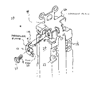
Figure I is a perspective view of the electrical device according to the
5 present invention;
Figure 2 is a top view of the pressure plate;
Figure 3 is a side view of the pressure plate;
Figure 4 is a bottom view of the pressure plate;
Figure S is a rear view of the electrical device; and
Figure 6 is a perspective view of the ground plate with the pressure
plate and a wire attached.
Detailed Description of the Invention:
A wiring device 10 of the type to which this invention relates is shown
in Figure 1. The wiring device 10 has a device body 20 with a neutral terminal
or terminals 13, a ground terminal 15, and a load terminal or terminals 15
mounted thereon for forming electrical connections to the device. The ground
terminal includes an electrically conductive ground plate 26, preferably a
metal plate that even more preferably forms the portion of the mechanical
structure of the wiring device 10, and includes an internal portion, not shown,
for making a connection to a receptacle for receiving a ground prong of an
electrical plug adapted to be engaged with the receptacle. The conductive
metal ground plate 26 is provided with a threaded through hole 38 extending
through a generally rectangular folded tab for receiving a threaded screw 18
having an enlarged head 34 and preferably provided, at a distal end thereof,
with an interruption 30 to the thread for preventing the screw 18 from being
fully withdrawn from the threaded through hole 38. The threaded through hole
38 in the tab may be located generally centrally with respect to the tab, or
preferably offset towards one edge of the tab, to reduce the possibility that two
separate wires will be connected to the tab.
A generally U-shaped pressure plate 12 having a generally flat base
~- - with a tapered concave bull nose 22 forrned at one edge thereof for receiving
and guiding an electrical connector under the plate 12, and first and second

CA 022103~9 1997-07-1~
legs 14, 16 preferably arranged at an approximately 90~ angle with respect to
the plate 12 for engaging cooperating openings or slots 44 in the ground plate
26 of the electrical receptacle adjacent to the tab to prevent the pressure plate
12 from rotating in use.
S Preferably, the pressure plate 12 has a relatively large uninterrupted
first portion 36 on one side of a central opening 24, that includes the bull nose
22 for entrapping the end of an electrical conductor between the pressure plate
12 and the ground plate 26 of the wiring device 10, thereby forming a
connectable contact device therebetween. Preferably, the pressure plate 12 has
a substantially reduced area 32 between the opposite edge of the plate 12 and
the central screw opening 24 for reducing the likelihood that a second separate
electrical wire will be connected to the ground plate 26 beneath the other side
of the pressure plate 12.
An electrical wiring device 10 having a pressure plate 12 in
accordance with this invention is easy to m:~mlfactllre. Preferably, as shown inFigure 6, a ground plate 26 is formed by appropliately punching and bending
a ground strap in a configuration shown in Figure 6 from a sheet of metal
material. A through hole 38 is formed in the tab of the ground plate portion 26
of the strap, and threaded to receive a screw 18 having an enlarged head 34
therethrough.
A pressure plate 12 having a generally U-shaped configuration with a
generally flat base 40 and first and second legs 14, 16 is positioned on the
ground plate 26 with the legs 14, 16 disposed in correspondingly shaped
recesses 44, 46 on the ground plate 26.
Preferably, a screw 18 is threaded into the central opening 24 of the
pressure plate 12 and the hole 38 of the ground plate 26 substantially
completely, so that the threaded end of the screw 18 protrudes from the plate
26 on the opposite side from the head. The threads at the end of the screw are
then preferably interrupted and deformed to prevent the screw from being
completely withdrawn from the threaded opening.
--- The pressure plate 12 engages the ground plate 26 of the receptacle
with the legs 14, 16 of the pressure plate 12 disposed within correspondingly

CA 022103~9 1997-07-1~
shaped recesses adjacent the ground plate 26 of the receptacle, so that the
pressure plate 12 is substantially constrained from rotation relative to the
ground plate 26, when the screw 18 is backed out sufficiently so that a wire 42
can be received between the ground plate 26 and the pressure plate 12. (See
S Figure 6). Without the cooperative restraining action of the legs 14, 16 in the
recesses 44, 46, the pressure plate 12 would be free to rotate and could readilybecome mic~ligned with the ground plate 26.
The combination of the ground plate 26, pressure plate 12 and screw
18 can then be assembled into a completed receptacle by way of the addition
10 of the rem~ining elements thereof, without concern that the pressure plate 12will become detached from the ground plate 26 or misprinted with respect
thereto.
While the invention has been described in connection with a presently
preferred embodiment thereof, those skilled in the art will recognize that many
15 modifications and changes may be made therein without departing from the
true spirit and scope of the invention9 which accordingly is intended to be
defined solely by the appended claims.

Representative Drawing
A single figure which represents the drawing illustrating the invention.
Administrative Status

2024-08-01:As part of the Next Generation Patents (NGP) transition, the Canadian Patents Database (CPD) now contains a more detailed Event History, which replicates the Event Log of our new back-office solution.

Please note that "Inactive:" events refers to events no longer in use in our new back-office solution.

For a clearer understanding of the status of the application/patent presented on this page, the site Disclaimer , as well as the definitions for Patent , Event History , Maintenance Fee  and Payment History  should be consulted.

Event History

Description Date
Inactive: IPC from MCD 2006-03-12
Time Limit for Reversal Expired 2003-07-15
Letter Sent 2002-07-15
Grant by Issuance 2000-09-05
Inactive: Cover page published 2000-09-04
Inactive: Final fee received 2000-05-03
Pre-grant 2000-05-03
Notice of Allowance is Issued 2000-01-13
Letter Sent 2000-01-13
Notice of Allowance is Issued 2000-01-13
Inactive: Approved for allowance (AFA) 1999-12-14
Application Published (Open to Public Inspection) 1998-04-09
Inactive: IPC assigned 1997-10-09
Classification Modified 1997-10-09
Inactive: First IPC assigned 1997-10-09
Inactive: Filing certificate - RFE (English) 1997-09-23
Filing Requirements Determined Compliant 1997-09-23
Letter Sent 1997-09-23
Application Received - Regular National 1997-09-22
Request for Examination Requirements Determined Compliant 1997-07-15
All Requirements for Examination Determined Compliant 1997-07-15

Abandonment History

There is no abandonment history.

Maintenance Fee

The last payment was received on 2000-06-19

Note : If the full payment has not been received on or before the date indicated, a further fee may be required which may be one of the following

  • the reinstatement fee;
  • the late payment fee; or
  • additional fee to reverse deemed expiry.

Patent fees are adjusted on the 1st of January every year. The amounts above are the current amounts if received by December 31 of the current year.
Please refer to the CIPO Patent Fees web page to see all current fee amounts.

Fee History

Fee Type Anniversary Year Due Date Paid Date
Application fee - standard 1997-07-15
Request for examination - standard 1997-07-15
Registration of a document 1997-07-15
MF (application, 2nd anniv.) - standard 02 1999-07-15 1999-06-16
Final fee - standard 2000-05-03
MF (application, 3rd anniv.) - standard 03 2000-07-17 2000-06-19
MF (patent, 4th anniv.) - standard 2001-07-16 2001-06-15
Owners on Record

Note: Records showing the ownership history in alphabetical order.

Current Owners on Record
PASS & SEYMOUR, INC.
Past Owners on Record
JAMES A. OSTERBROCK
MICHAEL R. BRYNDZIA
Past Owners that do not appear in the "Owners on Record" listing will appear in other documentation within the application.
Documents

To view selected files, please enter reCAPTCHA code :


To view images, click a link in the Document Description column. To download the documents, select one or more checkboxes in the first column and then click the "Download Selected in PDF format (Zip Archive)" or the "Download Selected as Single PDF" button.

List of published and non-published patent-specific documents on the CPD .

If you have any difficulty accessing content, you can call the Client Service Centre at 1-866-997-1936 or send them an e-mail at CIPO Client Service Centre.


Document
Description 
Date
(yyyy-mm-dd) 
Number of pages   Size of Image (KB) 
Representative drawing 1998-04-22 1 9
Description 1997-07-14 5 215
Abstract 1997-07-14 1 15
Claims 1997-07-14 2 74
Drawings 1997-07-14 3 47
Representative drawing 2000-08-30 1 9
Courtesy - Certificate of registration (related document(s)) 1997-09-22 1 118
Filing Certificate (English) 1997-09-22 1 165
Reminder of maintenance fee due 1999-03-15 1 111
Commissioner's Notice - Application Found Allowable 2000-01-12 1 166
Maintenance Fee Notice 2002-08-11 1 177
Correspondence 2000-05-02 1 36