Note: Descriptions are shown in the official language in which they were submitted.
CA 02210518 1997-07-15
WO 96/23293 PCT/US96/01170
-1-
A DEVICE AND PROCESS FOR GENERATING AND MEASURING THE
SHAPE OF AN ACOUSTIC REFLECTANCE CURVE OF AN EAR
= 5 Field of the Invention
The present invention relates generally to devices and processes which provide
information about a condition of an ear for use in diagnosis of ear
pathologies. More
particularly, the invention relates to devices and processes which involve
measuring acoustic
reflectance of components of the ear.
Backzround of the Invention
A wide variety of pathologies associated with the human and animal ears have
been
identified. The more frequently diagnosed pathologies include obstruction of
the external ear
canal, atresia of the external ear canal, perforation of the tyrnpanic
membrane, retraction of the
tympanic membrane, otitis in its various forms (adhesive, purulent and non-
purulent),
otosclerosis, fixation of the stapes, and cholesteatoma, among others. In
children, otitis media is
one of the most common pathologies. By itself, otitis media is a significant
affliction which can
lead to serious long-term hearing and learning disabilities if not promptly
diagnosed and treated.
Further, otitis media is frequently symptomatic of other pathologies, and thus
useful in their
diagnosis.
These ear pathologies are generally diagnosed using common diagnostic
techniques,
such as tympanometry, pneumatic otoscopy or visual otoscopy. While the
usefulness of these
techniques is well-recognized and established, these techniques do have some
difficulties. For
example, with both tympanometry and otoscopy, personnel who conduct tests and
interpret
results must be highly trained. Since these techniques cannot be performed by
non-medical or
inexperienced personnel, efficient screening of children or infants at home or
in a school is not
possible with these techniques.
Additionally, a patient must cooperate with the personnel performing these
tecluiiques,
but patients subjected to these techniques may experience considerable
discomfort. In particular,
discomfort from tympanometry or pneumatic otoscopy arises since (1) an
airtight seal is required
to obtain useful measurements, (2) any probe assembly must be inserted deep
into the ear canal,
and (3 )) the air pressure in the ear canal must be varied above and below
atmospheric pressure to
obtain useful measurements.
CA 02210518 1997-07-15
WO 96/23293 PCT/US96/01170
-2-
The diagnosis of otitis media in young children using common diagnostic
techniques is
particularly difficult because of the fear, discomfort or even pain,
associated with many of these
techniques. The usefulness of examination by conventional techniques is often
diminished
because discomfort of the child typically leads, at best, to movement by the
child which impairs
the examination and, at worst, to a refusal to allow the examination to
proceed. The problem is
especially acute when the examination is made in a mass screening environment,
such as may
take place in hospital clinics where large numbers of patients must be seen in
a comparatively
short time.
Many of the problems with these common diagnostic techniques were overcome by
a
device which measures acoustic reflectance, which is a quantity related to the
complex acoustic
impedance of the middle ear. A suitable device and methodology for measuring
acoustic
reflectance are disclosed and described in U.S. Patent Nos. 4,601,295 and
4,459,966 to John H.
Teele (the Teele patents). Such devices were made commercially available by
ENT Medical
Devices, Inc., of Wareham, Massachusetts, and Endeco, Inc., of Marion,
Massachusetts. In the
literature, this diagnostic technique is generally referred to as acoustic
reflectometry and the
device is generally referred to as an acoustic reflectometer or acoustic
otoscope.
Acoustic reflectometry involves transmitting sound waves (called incident
waves)
through the ear canal to the tympanic membrane. Some of the incident waves are
reflected off
the tympanic membrane and other components of the ear. The incident waves are
selected from
a range of frequencies including the resonance frequency of the tympanic
membrane; ideally the
amplitudes of the incident waves are also the same but this is often not
achievable. The vector
sum of these reflected waves with the incident waves is obtained by a
microphone. The envelope
of the vector sum of the incident and reflected waves over the range of
frequencies, herein called
an acoustic reflectance curve, has a dip, also called a null. The peak of this
dip, actually a
minimum, is known as a null value. In the literature and in their commercial
use, acoustic
reflectometers calculate an acoustic reflectance curve for an ear and detect
the presence and
frequency centerline of the dip and the null value. The null value is the
primary basis for
diagnosis of ear pathologies using such devices. Although the Teele patents
state that "shape" of
the characteristic dip can be detected along with the presence, frequency and
amplitude of the
dip, these patents do not discuss significance of the shape of the
characteristic dip other than that
shape means how pronounced or sharp the dip is. The Teele patents do not
discuss how shape of
the dip i-s detected or measured or how it is used in diagnosis.
CA 02210518 1997-07-15
WO 96/23293 PCT[IIS96/01170
-3-
One of the commercially available acoustic reflectometers was a "T"-shaped
device
which provided the amplitude of the null value and the incident frequency at
which it occurred
using a set of horizontal diodes to indicate the frequency at which a dip
occurred, and a set of
vertical diodes to indicate the null value. This device, the Mode1501 Acoustic
Otoscope from
ENT Medical Devices, Inc., could be equipped with a recorder, or printer,
allowing viewing of a
visual representation of the entire acoustic reflectance curve.
Several articles in the literature describe how the null value of an acoustic
reflectance
curve obtained using commercially available devices is correlated with ear
pathologies. In
particular, severe middle ear effusion (MEE) generally causes high null
values, whereas normal
ears cause low null values. However, there is a significant range of
measurements for which the
diagnosis is uncertain, e.g., probable MEE such as when an effusion is just
beginning to develop.
Such a range of uncertainty limits the sensitivity and specificity of the
process and device. The
literature also includes several studies which reach a variety of conclusions
on the specificity and
sensitivity of the device for diagnosing MEE.
It was discovered that the accuracy of the measurement of the null value
obtained with
an acoustic reflectometer depended on the line of sight from the instrument
tip to the tympanic
membrane. A direct line of sight provides the most accurate results. When a
direct line of sight
is not obtained, due to improper aiming or because of the ear itself,
measurements of the null
value are less likely to indicate an unhealthy ear and are more likely to fall
in the range of
uncertainty, indicating only probable MEE. An unhealthy ear may be diagnosed
as healthy.
Due to this range of uncertainty, commercially available acoustic otoscopes
were
eventually provided with operating instructions that directed a user to look
at the overall shape of
the dip, when the acoustic otoscope was used with a recorder or printer. It
was stated that, given
detection of a null value in the uncertain range, a somewhat rounded dip
suggests a dry ear
condition or negative pressure behind the tympanic membrane but no effusion.
It was further
states that a sharply peaked dip suggests a condition where the middle ear is
partly air-filled,
partly fluid-filled.
= These operating instructions were based primarily on a study by Jerome T.
Combs,
entitled, "Predictive Value of the Angle of Acoustic Reflectometry," in The
Pediatric Infectious
Disease Journal, vol. 10, no. 3, pp. 214-216, March 1991. This article states
that an "angle"
formed at the null of the acoustic reflectance curve, as displayed on the
Model 501 Acoustic
Otoscope with recorder, is useful in combination with the null value to
distinguish healthy ears
CA 02210518 1997-07-15
WO 96/23293 PCT/US96/01170
-4-
from unhealthy ears where the null value is inconclusive. Angle measurements
were performed
manually on the printout using a protractor or goniometer. The paper does not
describe any
controlled procedure by which points or lines on the printed acoustic
reflectance curve were
selected to define the angles being manually measured.
The article describes a study in which acoustic reflectance measurements were
obtained
for 406 ears of 203 children (96 girls and 107 boys) between the ages of 4 and
16 using the
Model 501 Acoustic Otoscope with recorder. Of this number, there were 75 ears
of
tympanometry type A, 149 ears of tympanometry type B and 182 ears of
tympanometry type C.
The purpose of the study was to determine whether the "angle" formed by the
dip in the acoustic
reflectance curve had any predictive value. Although the article does conclude
that such an
"angle" apparently has some predictive value, there are two problems with the
study that suggest
that the results lack adequate statistical significance to be conclusive about
this predictive value.
First, the number of subjects analyzed was arbitrarily selected. This actual
number of subjects is
statistically insignificant. A much greater sample would be more statistically
persuasive.
Second, the angle formed by the dip was measured manually using a protractor
on a printout of
the acoustic reflectance curve. Since the paper lacks a description of a
deterministic method for
establishing the points defining the angle, the angle measurements are likely
to have a fair
amount of a variance in them, further weakening the statistical significance
of the results.
While an acoustic reflectometer is a useful diagnostic tool, there remain some
unsolved
problems in achieving accurate diagnoses. First, inexperienced personnel are
more likely to
obtain inaccurate results because accurate measurement of the null value of
acoustic reflectance
still requires a direct line of sight from the tip of the acoustic
reflectometer to the tympanic
membrane. Second, the ears of young children reflect less of the incident
waves than those of
older children, given the same ear pathology. In particular, children under
six months of age
have a tympanic membrane which is at a relatively shallow angle to the ear
canal. In some cases,
this position of the tympanic membrane prevents a direct line of sight from
being obtained.
These two factors may result in a false measurement of the null value in a
"healthy" range for an
unhealthy ear.
Summary of the Invention
This invention is related to a device and a process involving measurement of
acoustic
reflectance of components of an ear. In one aspect of the invention, the shape
of a region of an
CA 02210518 1997-07-15
WO 96/23293 PCT/US96/01170
-5-
acoustic reflectance curve is measured electronically in order to obtain an
indicator of ear
condition which is substantially independent of a line of sight between a
sound source and the
tympanic membrane. This indicator is based on a measurement of the resonance
characteristic,
or freedom of motion, of the tympanic membrane or other ear component being
analyzed. One
such measurement is the rate of change of the acoustic reflectance with
respect to frequency.
Since resonance typically causes a null to appear in the acoustic reflectance
curve, this
measurement of the rate of change is particularly informative if measured
around the null. The
rate of change measured around the null may be presented as an angle
measurement, a gradient
or slope measurement, a width measurement, or another form of measurement of
the shape of the
null. In one embodiment, the steepest slopes on either side of a null are used
to define an angle,
herein called a spectral gradient. Diagnosis of an ear pathology, such as
abnormal pressure or
presence of fluid in the middle ear or such as conductive hearing loss, may be
based on this
measure alone.
Because of the rate of change of an acoustic reflectance measurement is
relatively
constant for a given ear, regardless of the quality of the line of sight to
the tympanic membrane,
the effect, if any, of user training on such measurements is significantly
reduced over the prior
art. Accordingly, the process and device of the invention are useful in many
kinds of diagnostic
situations with respect to ear pathology, but particularly in those involving
screening of the ears
of young children for common pathologies such as otitis media, even by
untrained personnel.
Accordingly, one aspect of the present invention is a device for analyzing
acoustic
reflectance of an ear having a tympanic membrane. This device measures
acoustic reflectance of
components of the ear for a plurality of frequencies by directing sound from a
sound source to
the tympanic membrane and by detecting reflected sound, wherein the measured
acoustic
reflectance has a shape. The shape of a region of the measured acoustic
reflectance is
electronically measured to obtain an indicator of a condition of the ear,
wherein the indicator is
substantially independent of a line of sight from the sound source to the
tympanic membrane.
Another aspect of the invention is a device for analyzing acoustic reflectance
of an ear
= having a tympanic membrane. This device includes an acoustic reflectance
measurement system
which directs sound of a plurality of frequencies to the tympanic membrane and
which detects
sound reflected by components of the ear to provide a measure of acoustic
reflectance having a
shape. A signal shape analyzer has an input connected to receive the measured
acoustic
CA 02210518 1997-07-15
WO 96/23293 PCT/US96/01170
-6-
reflectance and an output providing an indicator of a condition of the ear,
wherein the indicator is
substantially independent of a line of sight from the sound source to the
tympanic membrane.
Another aspect of the invention is a process for analyzing acoustic
reflectance of an ear
having a tympanic membrane. The process involves measuring acoustic
reflectance of 5 components of the ear for a plurality of frequencies by
directing sound from a sound source to
the tympanic membrane and by detecting reflected sound, wherein the measured
acoustic
reflectance has a shape. The shape of the measured acoustic reflectance is
electronically
measured to obtain an indicator of a condition of the ear, wherein the
indicator is substantially
independent of a line of sight from the sound source to the tympanic membrane.
In one embodiment of the invention, the indicator is a measure of the rate of
change of
.the acoustic reflectance with respect to frequency. In particular, the
measured acoustic
reflectance has a null indicative of resonance of the tympanic membrane at a
given frequencv and
amplitude. The measure of the rate of change around the null is a particularly
useful indicator.
In another aspect of the invention separately and in combination with other
aspects of
the invention, acoustic reflectance is measured by generating a plurality of
incident sound waves,
wherein each incident sound wave has a different fundamental frequency. Sound
waves from the
sound source and sound waves reflected by the ear are received and combined to
provide an
electrical signal indicative of a sum of the received sound waves. An envelope
of the electrical
signal provides the measured acoustic reflectance. The envelope may be
detected by determining
frequency domain components of the electrical signal from the transducer
corresponding to the
frequencv of the incident sound waves. In particular, such frequency domain
components may
be determined by computing the energy of the electrical signal corresponding
to the first
coefficient of a Fourier series representing the electrical signal.
Measuring the shape of a region of the measured acoustic reflectance may also
be done
by measuring a rate of change of a frequency domain component of the acoustic
reflectance.
This frequency domain component may be the first coefficient of a Fourier
series representing
the acoustic reflectance. Where the measured acoustic reflectance is
determined by measuring
energy in an electrical signal corresponding to the fundamental frequency of
the incident waves,
this measured acoustic reflectance may be differentiated to obtain a measure
of shape. In one
embodiment, the steepest slopes around the null define an angle which provides
the desired
measure of shape.
CA 02210518 1997-07-15
WO 96/23293 PCT/US96/01170
-7-
The measure of shape may be used alone as the basis for diagnosis. This
measure may
be simply displayed to a user or compared to one or more thresholds defining
ranges in which a
particular diagnosis is probable, such as otitis media, middle ear effusion,
abnormal pressure in
the middle ear or conductive hearing loss.
Brief Description of the Drawing
In the drawing,
Fig. 1 is a cross sectional diagram of an ear illustrating the principle of
acoustic
reflectance applied to a normal ear;
Fig. 2 is a schematic diagram illustrating a typical vector sum of the
incident and
reflected waves over a plurality of frequencies;
Fig. 3 is a graph illustrating an envelope of the vector sum shown in Fig. 2;
Fig. 4 is a cross sectional diagram of an ear illustrating the principle of
acoustic
reflectance as applied to an ear with an effusion;
Figs. 5A-5D are graphs illustrating typical envelopes of vector sums obtained
for an
effused ear;
Fig. 6 is a cross sectional diagram of a suitable test head for use with the
present
invention;
Fig. 7 is a block diagram describing a system in accordance with the present
invention;
Figs. 8A-8C are block diagrams of circuits for generating electrical signals
for
controlling the acoustic transducer of Fig. 7;
Figs. 9A-9C are block diagrams of circuits implementing the envelope detector
of Fig.
7;
Figs. l 0A-l OB represent the vector sum and corresponding envelope of the
reflectance
from an effused ear using a device in accordance with the invention;
Figs. 10C-1 OD represent the vector sum and corresponding envelope of the
reflectance
from open air using a device in accordance with the invention;
Fig. 11 is a block diagram of a circuit useful for normalizing the detected
envelope for
= nonlinearities in the acoustic system;
Fig. 12 is an example normalized envelope signal;
Fig. 13 is a block diagram of a circuit for implementing one embodiment for
measuring
the shape of a null in an acoustic reflectance curve;
Figs. 14A-B are graphs illustrating methods for performing an angle
measurement:
CA 02210518 1997-07-15
WO 96/23293 PCTIUS96/01170
-8-
Fig. 15 is a histogram showing a number of ears based on a measured angle
about the
null of the acoustic reflectance curve and an ultimate diagnosis;
Fig. 16 is a histogram showing the probable diagnosis for ears based on a null
value
corrected by an angle measured about the null of an acoustic reflectance
curve, as compared to
tympanometry type;
Fig. 17 is a scattergram plotting an angle measured about the null with
respect to
threshold voice audiometry values in decibels for a number of patients;
Figs. 18A - 18C are block diagrams of circuit elements for providing output to
a display
based on measurements of the acoustic reflectance curve;
Fig. 19 is a table comparing spectral gradient vs. reflectivity from acoustic
reflectance
curves obtained for a number of ears;
Figs. 20A and 20B illustrate suitable packaging for a diagnostic instrument in
accordance with the present invention; and
Figs. 20C and 20D illustrate suitable packaging for a screening instrument in
accordance with the present invention.
Detailed Description
The present invention will be more completely understood through the following
detailed description which should be read in conjunction with the attached
drawing in which
similar reference numbers indicate similar structures.
The process of measuring acoustic reflectance of an ear will first be
described in
connection with Figs. 1-5D. Fig. 1 shows a typical ear 100 having a tympanic
membrane (an ear
drum) 102, an ear canal 104, and middle ear 103. To measure acoustic
reflectance, a low
amplitude tone at a given frequency, indicated by line 105, is generated by an
acoustic
transducer, shown schematically at 106. The acoustic transducer generates
sound waves for
several frequencies, typically in the range of 500 hertz to 20 kilohertz. The
low amplitude sound
wave enters the ear canal and is incident on the ear drum 102. This sound wave
is absorbed in
part and reflected in part by the ear structures, including the tympanic
membrane, oscicles,
middle ear cleft and other components of the middle ear. The amplitude and
phase of the
reflected sound waves from these components are a function of the test
frequency used and the
complex acoustic impedance of the ear structures. In a healthy ear, some
minimal reflection
from the tympanic membrane and middle ear is expected. The complex acoustic
impedance of
CA 02210518 1997-07-15
W O 96/23293 PCT/US96/01170
-9-
the middle ear, in turn, depends very strongly on the conditions within the
middle ear, and in
particular on whether there is effusion, such as fluid, or abnormal pressure
present within the
middle ear. The vibration of a normal ear drum absorbs approximately half of
the incident
waves, resulting in weak reflected waves indicated by a line 107. A microphone
108 receives
both the incident wave 105, the reflected wave 107 and reflected waves from
ear components and
as a result obtains a vector sum of the values.
Fig. 2 represents the vector sum over a sweep of several frequencies, shown
with
decreasing frequency along the abscissa. This graph schematically shows a time
domain raw
data of the vector sum obtained from measuring an ear phantom. A rise, sharp
fall to a null and
then rise again is the characteristic resonance response of the tympanic
membrane of an ear or, in
this case, the ear phantom. The envelope of this curve is then determined to
provide a
measurement of the acoustic reflectance. This envelope can be determined in a
number of ways.
An envelope corresponding to the graph of Fig. 2 is shown in Fig. 3. In the
graph of Fig. 3, the
value of the envelope is shown on the ordinate and the wavelength of the
incident wave is on the
abscissa. The graph is similar to a printout from the Model 501 Acoustic
Otoscope with a
recorder. A null point 111 is observed in this envelope. On the scale shown,
the level of this
null is at about 2.0 units.
Referring now to Fig. 4, an ear 100 is shown to have effusion 110. The middle
ear
effusion limits ear drum vibration, causing large reflected waves to have a
larger amplitude as
indicated at 109. The envelope of a vector sum of incident waves 105 and
reflected waves 109
has a null at the quarter wave length points, as shown in Fig. 5A. In Fig. 5A,
the maximum
reflectivity. i.e., the minimum of the envelope of the vector sum, are about
7.2 units using the
reference system of the commercially available Model 501 Acoustic Otoscope, as
indicated at
112. In this example, the point with the lowest value, or highest
reflectivity, is the minimum
value over all frequencies of the envelope of the vector summation signal from
the microphone.
The reflectivity at the null point generally indicates middle ear problems
when it is greater than
5.0 units on the scale of the Model 501 Acoustic Otoscope.
In this invention, the shape of a region of the acoustic reflectance curve.
defined by at
least two points on the curve, is measured electronically to obtain an
indicator of ear condition
which is substantially independent of the line of sight between the sound
source and the
tympanic membrane. The indicator may be a measure of the rate of change of the
acoustic
reflectance with respect to a change in frequency on either or both sides of
the null. around the
CA 02210518 1997-07-15
WO 96/23293 PCT/US96/01170
-10-
null, of other regions of the curve or of the entire curve. The area around
the null is where the
curve has a significant negative slope, defining entry into the null, to a
point just before the null,
and after the null, where the curve has a significant positive slope, defining
the exit of the null.
The null typically occurs near the resonance frequency of the ear. The
significance of this
measurement will now be described.
As the sound wave incident to the tympanic membrane approaches a frequency
where
its quarter waves are coincident, the amplitude of the reflected sound waves
summed with the
incident sound wave approaches an amplitude null. Generally speaking, normally
conducting ear
drums without fluid or abnormal pressure in the middle ear demonstrate a
relatively shallow
acoustic null. Conversely, fluid or abnormal pressure in ears causes a
stronger reflection and
therefore a deeper acoustic null. The depth of this null is dependent,
however, on the line of
sight to the eardrum. It has been discovered, however, that the rate of change
of the acoustic
reflectance between the entry into the null and the exit from the null is
steeper for ears having
middle ear fluid or pressure than for healthy ears. It was further discovered
that differences in
this rate of change due to changes in line of sight have less of an impact on
the indication of the
presence of an effusion or abnormal pressure.
Referring to Fig. 5B, this graph shows a typical output of a Model 501
Acoustic
Otoscope with a recorder for an effused ear. This measurement was made by an
experienced
user who had a direct line of sight to the tympanic membrane. Fig. 5C however
shows the output
for the same ear with a deliberately poor line of sight. Finally, Fig. 5D
shows the output for the
same ear that is similar to that obtained by a typical inexperienced user. The
amplitudes of the
outputs for the same ear from Figs. 5B through 5D vary from 2.7, indicated at
114 according to
the Model 501 scale in Fig. 5C (typically considered normal), through 5.0 at
115 in Fig. 5D, to
7.6 at 113 in Fig. 5B (typically considered as indicating severe middle ear
effusion), whereas the
rates of change, i.e., slopes, before and after the null (used as an indicator
of envelope shape)
remain relatively unchanged.
Ear drums that are free to vibrate with the incident sound wave (i.e.,
healthy) produce
not only a less deep null but also a less steep slope at frequencies around
the null and thus a
smaller spectral gradient. The unrestrained motion produces lower reflectance
values relative to
the peak null at nearby frequencies and therefore an apparent lower slope.
When the ear drum motion is restrained, (i.e., the ear is not healthy) the
slope around
the null is steeper. Because acoustic reflectance is related to the complex
acoustic impedance of
CA 02210518 1997-07-15
WO 96/23293 PCT/US96/01170
-11-
the tympanic membrane, the measure of its rate-of change with respect to
frequency input is
analogous to measuring the "Q" of an electrical circuit. Thus, restraining the
ear drum results in
both a higher acoustic impedance and a sharper "Q". The "Q" is relatively
constant for a given
impedance regardless of variations in the amount of energy incident due to
line of sight
limitations.
A device in accordance with the invention will now be described. Fig. 6 is a
cross
sectional diagram of a test head for an instrument in accordance with the
invention. The test
head 12 includes a transducer 21 that creates a sound field in sound cavity
23. Sound in the
cavity 23 is channeled through probe 25 to the vicinity of the ear canal 290.
The probe has a
funnel-shaped section 251 and an optional linear section 252. The dimensions
of section 252
may be chosen to match the dimensions of the typical healthy ear canal under
test. This thereby
matches the impedance of the probe tip and the typical ear canal. For
children's ears, length A of
the linear portion 252 of the probe preferably is equal to approximately 1 cm
and inner diameter
B of the same section should be in the range of approximately 0.25 to 0.75 cm.
Similarly, good
results are obtained when length C along the side of funnel-shaped section 251
of the probe is
about 5 cm and the approximate outer diameter D of the large end of the probe
which is in
contact with the sound cavity wall is approximately 7 cm. With appropriate
compensation, tips
with other exit diameters may be used. The probe extension does not need to be
inserted into the
ear canal. In practice there may be a narrow gap 28 between the test head
probe tip 27 and the
entrance to the ear canal 290. Control of this gap may be facilitated by a
sponge rubber spacer
(not shown) attached at the end of probe tip 27.
The incident sound wave created by transducer 21 in the test head emanates
from the
test head at the tip 27 of the probe 25 and enters the ear cana1290.
Thereafter, a portion of the
incident wave is reflected by structures of the ear. Minimal reflection from a
healthy ear can be
suppressed by suitable selection of the inner probe tip diameter, e.g. by
enlarging it to 1.0 cm for
children.
Portions of the reflected waves enter at tip 27 into the hollow linear portion
252 of the
test head. The microphone 24 is located within the test probe 25 at the
junction of the linear
portion 252 and the funnel-shaped section 251. As a result, the microphone 24,
in effect,
measures the net sound pressure at this point; this net sound pressure is the
vector sum of the
incident and reflected signals. In order to reduce internal sound reflection
and resonances within
the test head, the sound cavity 23 may be filled with acoustic absorbing
materials.
CA 02210518 1997-07-15
WO 96/23293 PCT/US96/01170
-12-
Having now described the general principles of acoustic reflectometry, and a
suitable
test head for use in an acoustic reflectometer, electronic circuitry suitable
for practicing the
present invention will now be described in connection with Figs. 7-12. A
general block diagram
of a device in accordance with the invention, including its electrical and
mechanical components,
will now be explained in connection with Fig. 7. The components of this
circuit may be
implemented using a microprocessor, except for the display, acoustic
transducer and microphone.
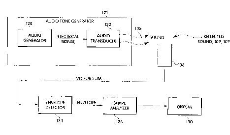
An analog implementation may also be made. In Fig. 7 an audio tone generator
121 includes an
audio generator 120, which produces an electrical signal which is applied to
an audio transducer
122 (such as transducer 21 in the test head of Fig. 6). The audio transducer,
in response to the
electrical signal, generates a low level acoustic sound wave (105 in Figs. 1
and 4) which is
applied to the outer ear canal. The audio transducer 122 may be an electronic
earphone,
electromagnetic earphone, or other type of transducer. The transducer may be a
small
loudspeaker such as used in high fidelity sound headsets.
A portion of the incident sound wave is reflected by ear structures as
described above.
These reflected waves are summed with an incident wave by microphone 108 (such
as
microphone 24 of the test head of Fig. 6). The microphone may be a condenser
microphone, an
electrostatic microphone or other kind of microphone. The signal output by the
microphone
represents the vector sum of the incident wave and the reflected sound waves,
having a voltage
which is inversely proportional to the amplitude of the reflected waves as
shown schematically in
2o Fig. 2.
An envelope detector 124 converts the vector sum represented by the signal
output by
the microphone to an envelope signal represented by a voltage which varies
with the frequency
of the incident wave. The envelope detector 124 may be implemented as a peak
value envelope
detector, a root-mean square (RMS) voltage detector, or analog-to-digital
converter, such as part
of a suitably programmed micro-processor. In one aspect of the invention
described in more
detail below, the envelope is detected using information about the frequency
spectrum of the
vector sum. The envelope so detected is called the acoustic reflectance curve.
A shape analyzer 126 electronically measures the shape of a region of the
acoustic
reflectance curve to obtain an indicator of ear condition which is
substantially independent of the
line of sight from a sound source to the tympanic membrane. This information
may be one or
more measures of the shape of the envelope including a measure of the rate of
change of acoustic
reflectance with respect to a change in frequency around the null, on either
side of the null or on
CA 02210518 1997-07-15
WO 96/23293 PCT/US96/01170
-13-
a region of the curve or of the entire curve. This measure, for example, may
be an angle,
gradient, slope, width, or other measure of the shape of the acoustic
reflectance curve determined
in a manner to be described below. This information is then displayed in a
suitable format by
display section 130.
In Fig. 7, a memory (not shown) may be added to store results of processing of
one
acoustic reflectance curve. With such a memory, the circuit may be operated to
perform
automatically a number of tests sequentially on the ear. The best result for
the sequence of tests
may be kept and the others may be discarded. For example, the best result
could be defined as
the measurement of the shape of the acoustic reflectance curve having the
deepest null value. In
Io this manner, a user of the device may attempt to get the best result with
little effort.
The audio generator 120 will now be described in more detail in connection
with Figs.
8A-8C. The output of the audio generator 120 to be applied to the audio
transducer 122 is a
series of sine waves swept over a range of different frequencies. Typically,
the sweep may be in
a range from 500 hertz through about 20 kilohertz. Ranges of 1 kilohertz to 15
kilohertz, 1.8
kilohertz to 7 kilohertz, and 1.8 kilohertz to 4.4 kilohertz are acceptable. A
typical period for a
full sweep may range from 20 milliseconds to about 10 seconds. These are,
however, only
example figures. In general, there should be a frequency output that covers
one or more of the
resonant points of the ear canal "transmission line" as "terminated" by the
middle ear. These
points occur regularly at multiples of one quarter wavelength. The following
resonant points
have been found to be particularly useful for screening purposes: 1/4 wave,
'/2 wave, 3/4 wave,
and one wavelength. In a normal adult ear these wavelengths correspond to
frequencies of
approximately 3.5, 7, 10.5, and 14 kilohertz.
In Fig. 8A, the audio generator 120 (Fig. 6) is implemented using a ramp
generator 140.
The ramp generator 140 generates a ramp signal 141, i.e., a monotonic signal,
which drives a
voltage controlled oscillator (VCO) 142. The ramp signal is also used by the
envelope detector
124 and the display 130 as described below. The VCO 142, in response to the
ramp signal,
provides a swept sine wave having a range of frequencies defined by the ramp
signal. The swept
sine wave is applied to the audio transducer 122.
Fig. 8B is a block diagram of the audio generator 120 in an embodiment
utilizing
analog techniques with a continuous sweep system. A swept frequency source 31
provides a
swept frequency output over line 312. The sweep signal itself appears as an
output over line 311
for use in controlling the envelope detector 124 and display 130. The sound
pressure from the
CA 02210518 1997-07-15
WO 96/23293 PCT/US96/01170
-14-
transducer is kept at a constant level by feedback from the test head over
line 322 to an attenuator
32. The voltage-controlled attenuator in this embodiment is continuously
adjustable to a
maximum of 20 decibels. Its output is provided to a power amplifier 33 which
drives the audio
transducer.
In the embodiment of Fig. 8C, a train of pulsed signals is used, each pulse at
a different
frequency. Components bearing numbers corresponding to those numbers discussed
in
connection with Fig. 8C function in a manner analogously to the
correspondingly numbered
components in Fig. 8B. In the embodiment shown in Fig. 8C, however, the signal
to the test
head originates with the pulse-sweep generator 51. This pulse-sweep generator
provides a series
of pulses, each of which has a width of approximately 10 milliseconds, with a
pulse repetition
rate of approximately 100 hertz. Each pulse has a different center frequency,
the first pulse
having a frequency of approximately 1.8 kilohertz. Each succeeding pulse has a
center
frequency proportionately higher than its predecessor pulse, until the final
pulse in a given train
of pulses has a frequency of approximately 4.4 kilohertz. A sequence of about
44 pulses of
different frequencies is suitable. A complete screening measurement can be
made with about a
0.5 second-long burst of these pulses of sine waves. Preferably, a
microcontroller synthesizes a
burst of several cycles for each sine wave frequency at discretely timed
steps. The sequence of
pulses is applied to the signal attenuator 32 of which the output is applied
to a wideband power
amplifier 331. The trigger out signal 313 from the pulse sweep generator is
used by the display
130.
It should be understood that these embodiments of the audio generator 120 are
exemplary only. Other embodiments are also possible. For example, frequency
domain methods
for generating an envelope, described below, do not require a sequential
generation of probe
frequencies with individual measurements at each discrete frequency. Broad
band acoustic
excitation with adequate energy distribution in the frequency range of
interest also results in
good frequency domain measurements using transforms to the frequencv domain,
such as Fourier
transforms and other similar methods. White noise generation may accomplish
this spectral
energy distribution.
The envelope detector 124 will now be described in more detail in connection
with
Figs. 9A-9C. In the embodiment shown in Fig. 9A, the envelope is determined by
root-mean-
square to direct current (RMS-to-DC) conversion. In Fig. 9A, the output from
the microphone is
sent over line 341 from the test head 34 through a preamplifier 35 to a
bandpass filter 36. The
CA 02210518 1997-07-15
WO 96/23293 PCT/US96/01170
-15-
bandpass filter typically passes signals from approximately 500 Hz to 20 kHz.
The output of the
bandpass filter 36 is input to an RMS-to-DC converter 371, which outputs a
measure of the total
energy of the vector sum signal from the microphone for the frequency of each
incident sound
wave. The RMS-to-DC converter 371 is controlled, in this embodiment, by a
sweep out signal
311, such as from the swept frequency source of Fig. 8B.
The embodiment of Fig. 9B is based on peak detection. In Fig. 9B, similar to
Fig. 9A, a
wide band preamplifier 35 receives the output of the microphone. The output of
the preamplifier
is passed through bandpass filter 36. The output of the band pass filter is
input to a peak detector
372 which generates the envelope by extracting the peak value for the
frequency of each incident
sound wave. This peak detector may be controlled, for example, by a trigger
out signal such as
from a pulsed sweep generator 51 shown in Fig. 8C. One difficulty with this
embodiment is that
it is particularly sensitive to noise transients.
The embodiment shown in Fig. 9C uses frequency domain information of the
vector
sum to determine the envelope. This embodiment is based on the principle that
an acoustic
signal, or its electrical analog, may be represented by a series of sine waves
of different
frequencies (the Fourier series). Each frequency has associated coefficients
that determine its
overall amplitude. Summing all the coefficients of the Fourier series
reproduces the original
wave shape. The first coefficients correspond to the fundamental frequency.
The higher
coefficients of a pure sine wave are zero. In this embodiment, the series of
sound waves
generated by the acoustic reflectance instrument is a series of sine wave
bursts of several cycles,
with each burst at a different frequency. Knowing the fundamental frequency of
each burst, the
first coefficients of that signal represent only the fundamental frequency.
All other frequencies
can be ignored.
Ignoring all frequencies other than the fundamental frequency, the energy of
the
received vector sum signal may be expressed as the sum of the squares of the
Fourier coefficients
of the fundamental frequency. These coefficients are the products between the
vector sum signal
and the sines and the cosines of the fundamental frequency. The energy is thus
defined by
equation (1) below:
Ef = [2:VX sin (2rrt)]2+[yVX cos (2TTt)]' (1)
CA 02210518 1997-07-15
WO 96/23293 PCT/US96/01170
-16-
where Ef is the energy at the incident frequency f, and VX is the vector sum
voltage at the incident
frequency. The summation symbol indicates that this product is calculated for
each sample of
the vector sum voltage over an integer number of cycles of the vector sum
signal. This energy of
the fundamental frequency of the acoustic wave is measured by an energy
measurement section
37 in Fig. 9C. The square root of the energy value Ef yields the RMS value of
the component of
the signal that contains only the fundamental frequency. The envelope is
defined by the RMS
value for each incident frequency.
One benefit of this embodiment is that measuring the energy of the vector
summed
signal for the fundamental frequency over several cycles should substantially
reduce effects of
external noise and provides a meaningful quantitative value associated with
that frequency.
Thus, the measured energy at each of the incident frequencies provides a
relatively noise-free
envelope of the tympanic membrane's resonance characteristics in response to
the series of
incident sound waves. Thus, sounds from a crying child and ambient room noise
are eliminated
if their frequency content is not at the fundamental frequencies being
measured.
It is also useful in this invention to normalize the envelope detected by
envelope
detector 124 to account for nonidealities of the acoustic system, including
the microphone,
traiisducer, acoustic chamber and tip, from which the vector sum is obtained.
This normalization
is based on an assumption that if the incident waves were applied to open air,
there should be no
measured reflection. Thus, the resulting curve of the vector sum and its
envelope should be flat.
However, due to nonidealities in the acoustic system, the resulting curve is
typically not flat.
For example, an actual vector sum obtained with a device using a continuous
sweep
audio tone generator as applied to open air is shown in Fig. 10C. In this
Figure, the abscissa
represents either increasing time or the frequency of the incident wave in
arbitrary units. The
ordinate represents the amplitude of the vector sum output by the microphone
in arbitrary units.
Fig. 1 OD represents the envelope of this vector sum using the method
described in connection
with Fig. 9C. In this Figure, the abscissa represents increasing time or
frequency of the incident
wave in arbitrary units. The ordinate represents the magnitude of the envelope
in arbitrary units.
There are noticeable irregularities in the envelope shown in Fig. l OD.
Fig. I OA shows the vector sum as obtained from an ear phantom, a mechanical
construction that is acoustically similar to an actual ear. In this Figure,
the abscissa represents
increasing time or frequency of the incident wave in arbitrary units. The
ordinate represents the
amplitude of the vector sum output by the microphone in arbitrary units. Fig.
1 OB is a graph
CA 02210518 1997-07-15
WO 96/23293 PCT/US96/01170
-17-
illustrating the envelope of the vector sum shown in Fig. l0A detected using
the method
described in connection with Fig. 9C. In this Figure, the abscissa represents
increasing time or
frequency of the incident wave in arbitrary units. The ordinate represents the
magnitude of the
envelope in arbitrary units.
Before analyzing the shape of the curve shown in Fig. l OB, it is preferable
to normalize
the envelope shown therein using the knowledge of the irregularities of the
acoustic system as
revealed in Fig. l OD. Thus, for each frequency for which data was stored for
the acoustic system
as applied to open air (from Fig. 10D), the reciprocal of the value of the
envelope for each
frequency is used to scale the value of the envelope at the corresponding
frequency in the curve
obtained for a given ear (e.g., in Fig. lOB).
A circuit for performing this normalization is shown in Fig. 11. The envelope
detector
124 has an output applied to a multiplexer kMUX) or other selector 123 which
is controlled
according to a mode selection signal applied through line 123A. In a first
operational mode
called normalization mode, the device is directed to transmit sound into open
air and the output
of the envelope detector is supplied via MUX 123 to a memory 125 where it is
stored. In a
second operational mode called measurement mode, when measurements on an ear
are
performed, the output of the envelope detector is applied through the
multiplexor 123 to a scaling
section 127. For each frequency of incident waves applied to the ear, the
value of the envelope at
that frequency is scaled by the reciprocal of the value for the same frequency
stored in memory
125 to provide a normalized envelope output. Such an exemplary normalized
envelope is shown
in Fig. 12. In this Figure, the abscissa represents increasing frequency in
arbitrary units. The
ordinate represents the magnitude of the envelope in arbitrary units. Note
that the curve of Fig.
12 is substantially smoother than the envelope of Fig. 1 OB.
Further digital signal processing may be performed on the normalized envelope
to
reduce noise in the curve, or in regions of interest in the curve. For
example, low pass filtering
can be performed on the region having a negative slope prior to the null
value, e.g. using a three-
tap filter. The region having a positive slope after the null value may also
be filtered, e.g.. using
a five-tap low pass filter. The information for an entire curve could also be
discarded if
insufficient amplitude is obtained for the null value. These and other kinds
of digital filtering
may be performed. For example, the acoustic reflectance envelope may also be
scaled for use in
angle measurement and waveform plotting.
CA 02210518 1997-07-15
-18-
A suitable shape analyzer 126 will now be described in more detail. The shape
analyzer
126 electronically measures the shape of a region of the acoustic reflectance
signal. A number of
regions may be of interest. The region of primary interest is the region
around the null.
Additionally, the portion of the negative slope at the entry of the null may
also be significant and
contain diagnostically useful information. The positive slope following the
null and the peak-to-
peak amplitude of the resonance waveform may also be useful. The shape
analyzer 126 may, in
addition, electronically determine the location and amplitude of the null of
the detected
waveform using a form of null detector which detects minimum voltage values.
In Fig. 13, the shape analyzer detector 126 is implemented using a null
amplitude
detector 144 which determines a null voltage. The null voltage is applied to a
voltage
comparator 146 which also receives an offset voltage. The combination of the
null voltage and
an offset voltage act to provide a control signal back to the ramp generator
140 (via line 146A)
for use as will be described below. Similarly, the control signal is applied
to an integrator 148
for reasons to be described below. The vector sum may also be applied from
microphone 108 to
the integrator.
The operation and cooperation of the ramp generator 140, voltage comparator
146 and
integrator 148 will now be described. Their co-action implements the
integration method
described above. After detection of a null voltage, an offset voltage above
the null voltage is
determined. The ramp generator is allowed to sweep through the set of
frequencies one
additional time. When the output voltage of the microphone meets the offset
voltage, the
integrator 148 is turned on and begins to perform an integration as the
voltage decreases to the
null voltage and then back up to the offset voltage. The output signal of the
integrator after the
second rising offset voltage is met provides a value proportional to the angle
of the null. This
value is provided to a voltage comparator 150 which provides an output
indicative of whether the
angle is less than or greater than one or more threshold angles. These outputs
are applied to a
display, such as to light emitting diodes 152 and 154.
There are several ways to measure the shape of a region of the acoustic
reflectance
curve, including measuring the gradient or slope. The shape of a region
defining a dip may be
measured by examining gradient or slope of the sides of the dip, or by
measuring an angle
defined by the dip or by measuring the width of the dip.
Methods for measuring the shape of the region of the acoustic reflectance
curve around
the null will first be discussed. These methods are related to measuring the
slope of the line on
Ftt4;E-NDED SiiEET
CA 02210518 1997-07-15
_19_
either side of the null in terms of, for example, frequency per volts, where
the measure of the
vector sum output from the microphone is a voltage.
In one embodiment of the invention, the measurement of the shape of the null
is
presented as a measurement of an angle formed by the null in the acoustic
reflectance curve as if
the curve were printed by the recorder of the Model 501 Acoustic Otoscope. In
order to achieve
this, the acoustic reflectance curve is scaled to match the scale of the Model
501 Acoustic
Otoscope. To perform such scaling, for each frequency f to be represented on
the abscissa, its
actual position L on the abscissa is determined by the product of its offset
from the first
frequency fo in the range to be displayed and the width W of the plot, e.g.,
84 rnin, divided by the
l0 frequency range f, as follows: L=(f-fo)* W/ fr
Each of the corresponding reflectivity values R is computed according to the
following equation:
R=A*H/A1800,
where A is the amplitude, H is the plot height, e.g., 40 mm. These scaling
formulas are merely
illustrative for the Model 501 Acoustic Otoscope. Other scaling formulas could
also be used.
Given the values as scaled to an appropriate reference frame, such as the
display of the
Model 501 Acoustic Otoscope, angles or other measurements of the shape of the
null and other
regions of the acoustic reflectance curve can be computed.
A first method involves a frequency gradient/amplitude reference. First, an
amplitude
value is established for the null apex. Second, the frequency is measured for
the location on each
side of the null where the amplitude reaches a known incremental voltage value
above the null
value. This incremental voltage typically may be about 20% of the possible
voltage output range
of the envelope detector 124 (Fig. 7). Generally speaking, this incremental
voltage should
provide a point on the curve after entry to the null but before leveling off
in the curve very close
to the null point, for a typical unhealthy ear. For example, the incremental
voltage may
correspond to two reflectivity values on the Model 501 Acoustic Otoscope. The
incremental
voltage may also be made proportional to the voltage at the null value to
provide for a
normalization effect. The frequency at this voltage may be determined by
sampling the output of
the audio generator 120 (Fig. 7) or ramp generator 140 (Fig. 8A). The
difference in the two
frequencies is the desired result.
A second method involves a frequency increment measurement. More particularly,
the
frequency of the null apex is established. Then, the relative amplitude is
measured at a known
incremental frequency above the apex frequency. The corresponding relative
amplitude is found
AMENDED SHEET
CA 02210518 1997-07-15
-1!0-
for an incremental frequency below the apex frequency. Generally speaking the
incremental
frequency should provide a point on the curve after entry to the null but
before leveling off in the
curve very close to the null point for a typical unhealthy ear. The
incremental frequency may
generally be within 10 and 1000 Hz. The vector sum of the relative amplitudes
and
corresponding frequencies is the desired result.
A third method is called an integration measurement. With this method, after
the
amplitude of the null apex is established, the frequency is then scanned from
an incremental
voltage threshold on one side of the null to the same or similar value on the
opposite side of the
null. The incremental voltage may be the same as used in the first method. A
current integrator
to is activated between the two thresholds. The resulting integrated voltage
is used as a relative
number. Alternatively, the output of the audio generator 120 (Fig. 7) or the
output of the ramp
generator 140 (Fig. 8A) may be sampled on the opposite sides of the null and
the difference may
also be used as the desired result.
Yet another method is called a slope measurement. After the frequency of the
null
angle apex is established, the slope of one side of the angle is measured by
dividing the
frequency difference by the voltage difference (or vice versa) from another
point on the curve.
The slope of the other side is similarly measured. The difference in slopes is
used as the desired
result. Transcendental functions may be used to determine the angle in degrees
from this value.
As an example, referring to Fig. 14A, knowing both the frequency generation
and null voltage
calibration allows either angle, slope or gradient measurements to be made.
The amplitude value
(VO) and corresponding frequency (fD) at the null is stored in memory. Then
the two frequencies
corresponding to a given voltage offset are measured as fl and f2. Referring
to Fig. 14A, the
angle a1 = arctan [(fl - fO)/(V1-V0)] and angle a2 = arctan [(f0 - f2)/(V0-
V2)]. The null angle a
then is the sum of al and a,. When the scale used to represent the acoustic
reflectance curve is
the same as that used for the display of the Model 501 Acoustic Otoscope, the
angle so measured
corresponds to an angle as it would appear on the display of the Model 501.
Yet another method for measuring shape of the null involves a frequency domain
analysis, such as a Fourier transform analysis or similar transforms, herein
called the spectral
gradient measurement. The Fourier transform is a mathematical method of
analyzing an
electrical signal in the frequency domain as opposed to the more conventional
time domain.
When the envelope of the vector sum is generated using a Fourier series as
described above in
connection with Fig. 9C, differentiating the transformed signal results in a
direct measure of the
AMENDED SHEET
CA 02210518 1997-07-15
W o 96/23293 PCT/US96/01170
-21 -
frequency gradients within the signal. Summing the angles corresponding to the
steepest
negative and positive gradients on either side of the null provides a direct
measure of an angle
around the nmill. In particular, as shown in Fig. 14B, for the sake of
illustration, point A and
point B are assumed to be the points with the steepest gradients, called "a"
and "b". The angle a
defining the shape of the null is the sum of angles al and a2. In this
embodiment, in contrast to
Fig. 14A, a 1= -n/2 - arctan(a) and a2 = 7ti/2 - arctan(b).
Another method for measuring shape is a wavelet analysis of the detected
envelope.
Wavelet analysis can be used to extract multiple features from the envelope.
The features thus
obtained are distinctive features of the envelope since they can be used to
define the envelope.
These features could then be used as the basis for diagnosis. Such features
also allow
classification of various envelopes using neural network and/or other pattern
recognition
methods. Pattern recognition methods may also be used to extract features from
the envelope.
Given the information obtained by measuring the shape of the acoustic
reflectance
curve, an instrument having an output presenting this information in the form
of a likely
diagnosis is possible. For example, as shown in Fig. 18A, a screening module
430 can be used to
compare an input shape measurement to a threshold 432. The result of this
comparison can be
presented to a user as "healthy" or "unhealthy". Another possible
implementation, shown in Fig.
18B, is to use the shape information, such as an angle to weight, to correct
the reflectivity or null
value obtained. This correction accounts for errors due to line of sight
differences. A correction
module 434 receives the null value and shape information, such as an angle,
and computes the
corrected value to be output. Fig. 18C combines both the screening module 430
and the
correction module 434.
The correction module 434 will now be described in more detail. This module
can be
implemented in many different ways and can perform the correction in many
different ways. A
typical form of a suitable function for correction (ACR) of the measure of
acoustic reflectance by
the measured angle is:
ACR = AR * N
(M + Angle)
where AR = the acoustic reflectance at the acoustic null;
N a selected constant multiplier;
M a selected constant; and
Angle = the measured null angle.
CA 02210518 1997-07-15
WO 96/23293 PCT/US96/01170
-22-
This formula creates a suitable threshold at the midpoint reflectance value of
5.0 at an angle of
82 , with N set at 200 and M set at 118, respectively, as will be described in
more detail below.
The selection of the parameters of this function may be done empirically so as
to maximize the
sensitivity and the specificity of a given threshold.
To implement the weighting function, a microprocessor may be used to calculate
a
corrected value when the angle and reflectance values are input using the
formula as described
above. However, to accomplish both corrections described above plus make end
point
corrections would result in unnecessary complexity. The complexity of the
microprocessor
needed to perform such calculations in real time might substantially increase
the cost of an
instrument and the power required by the circuitry. A cost-effective
alternative is to utilize a
read-only memory look up table whose input address is the two variable values,
gradient and
reflectance, with the corrected value stored at the location in the read-only
memory
corresponding to the input address. Given any input address, the corresponding
weighted value
is provided at the output, to be displayed and printed.
This invention is well-suited for a screening instrument for use by non-
medical
personnel. Such a screening instrument uses one or more threshold values for
the shape
measurement to provide a simple output, such as "HEALTHY", "CONTINUE
MONITORING"
or "REFER" to a physician. It has been determined empirically, as shown in
Fig. 15, that for an
angle representation of the shape measurement, a threshold or suitable cut-off
point above which
an ear is healthy is about 95 degrees, where the angle is measured using the
spectral gradient
method described above. Fig. 15 is a histogram showing the number of patients
(out of 498)
having a given spectral gradient measurement, and grouped together according
to diagnosis, i.e.,
whether the patient was ultimately diagnosed with otitis media or was
otherwise healthy. Bars,
such as 160, having diagonal hash marks, for each given spectral gradient
indicate the number of
patients having the spectral gradient measurement and which were diagnosed
with otitis media.
Bars, such as 161, having vertical hash marks, for each given spectral
gradient indicate the
number of patients having the spectral gradient measurement and which were
diagnosed as
having healthy ears. Cut points are established to define thresholds
for.diagnosis. Suitable
thresholds are: 95 degrees, above which the patient is healthy with a high
probability and 75
degrees, below which the patient has otitis media with a high probability
(about 90%). The
range between 75 and 95 degrees indicate patients whom should be monitored for
possible
development of otitis media. Other thresholds below 75 degrees may also be
used to increase the
CA 02210518 1997-07-15
WO 96/23293 PCT/US96101170
- 23 -
probability of the diagnosis, e.g., 65 degrees arrid 55 degrees. These
thresholds were selected
empirically so as to simultaneously maximize the sensitivity and the
specificity.
Fig. 16 is a histogram based on the acoustic reflectance measurements for ears
of 1393
patients, corrected by a measured spectral gradient, grouped according to
tympanometry type.
Correction was made using the formula described above. In this figure, curve
133 corresponds to
tympanometry type A (674 patients), curve 131 corresponds to tympanometry type
C (462
patients), and curve 132 corresponds to tympanometry type B (257 patients). It
can be shown an
acoustic reflectance value of greater than 5 can clearly distinguish between
normal and unhealthy
ears. For this value as a threshold, a sensitivity of 0.94 and a specificity
of 0.97 was obtained. It
may also be advantageous to continue to use two or more thresholds. An
instrument for use by
non-medical personnel may also be made using this information as the basis for
diagnosis.
Referring now to FIG. 17, the correlation of conductive hearing loss to the
angles is
shown. Fig. 17 is a scattergram based on the angle of acoustic reflectance
measurements and
threshold voice audiometry measurements for ears of 68 patients. It is shown
in this figure that
all patients with an audiometry threshold of 25 dB or greater had a null angle
measurement of
less than 90 degrees. For this data set, a sensitivity of 1.0 was obtained.
Accordingly, an
instrument for use by non-medical personnel for detecting a likelihood of
conductive hearing loss
may also be made.
Referring now to Fig. 19, the improved independence from the line of sight for
the
spectral gradient measurement described above over the null value alone for
diagnostic purposes
will now be described. In tests from which the data of Fig. 19 was gathered,
at least four
measurements were taken for each ear. Average values of the null value and
spectral gradient
were taken, and maximum and minimum values were referenced to the average to
obtain above
average, below average and spread values. The spread value is the sum of the
minimum and
maximum differences from the average. A change in spread was determined for
each ear which
indicates the improvement in the spread from the null value to the spectral
gradient
measurement.
A significant finding is that as the spread in reflectivity values, in column
500, grew
larger, the improvement of the spread in the spectral gradient measurement, in
column 502, grew
larger. This improvement is defined by the average ratio of reflectivity
spread to the spectral
gradient spread. That is. the ratio, column 502, is the percent spread of the
null value divided by
the percent spread of spectral gradient. For ears with a reflectivity spread
of 50% or greater, the
CA 02210518 1997-07-15
WO 96/23293 PCT/US96/01170
-24-
spectral gradient measurement improved the spread by an average of 45.9
percentage points;
25.4 percentage points improvement was achieved for all reflectivity spreads
of 30% or greater,
etc. Thus, the average improvement is nearly three to one for reflectivity
spreads of 30% or
greater.
Embodiments of an instrument which analyze acoustic reflectance to obtain
shape
measurements, including spectral gradient measurements, to provide diagnostic
output to a user
will now be described in connection with Figs. 20a-20d. It should be
understood that these
embodiments are merely exemplary and not limiting. Other configurations are
possible and will
depend on the particular condition intended to be diagnosed, e.g., otitis
media, effusion, hearing
loss or abnormal pressure or other conditions, and the user, e.g., doctor,
trained personnel or
untrained personnel.
Figures 20a-20b illustrate one embodiment of an instrument in accordance with
the
present invention. This embodiment is intended for use as a diagnostic product
for hospital or
clinical use in diagnosis of ear pathologies by trained professionals, such as
doctors and other
primary care providers. The device is preferably battery-operated and uses
modern low-power
circuitry and power conservation techniques to minimize power consumption. For
example,
circuits preferably are used only Nvhen required and the system automatically
enters a stand-by
mode when not in use.
In this embodiment, the instrument has a hand piece 400 with replaceable tips
402 that
contact the patient. The shape of the hand piece is intended to more closely
resemble that of the
ubiquitous otoscope. A debounced measure button 403 is provided to start a
sweep by the
oscillator to obtain a measurement.
This output of this instrument is similar to that of the commercially
available Model
501 Acoustic Otoscope, but also provides the measure of the shape of the
curve. A numeric null
value also may be displayed, or a corrected null value may be displayed.
Therefore, the
hand-held instrument displays on its output 412 both the acoustic reflectance
curve at 414 and
the numeric results 416 on a low power LCD graphics display 418 in relative
units corresponding
to the established numbers as reported in the literature. In contrast to the
Model 501 output, the
ear canal length number need not be shown when the entire acoustic reflectance
curve is
graphically displayed on the instrument.
It may also be desirable to provide an additional memory (not shown) for
storing data
for later retrieval. By providing sufficient memory, multiple sets of measured
data may be stored
CA 02210518 1997-07-15
25 -
in the memory in the hand-held instrument for later plotting. Buttons may be
provided to store
or otherwise access the data in the memory. For example, left and right ear
buttons (420 or 422)
may be provided. These buttons may be used to direct the null value to a
memory location which
stores the last peak data for later printing. The ear being tested may be
identified as Left or Right
on a printed record.
As an additional feature, two or more sizes of replaceable tips and
normalization data
may also be provided for selecting the age group being tested. For example,
simultaneously
pressing the Left and Right ear buttons may be used to cause toggling between
Child and Infant
tip calibration. Switching to infant operation selects a higher swept
frequency range and internal
circuit gain while the infant tip adjusts the apparent canal length and
modifies the acoustic
impedance. Normalization data for the two types of tips may be stored in non-
volatile memory,
eliminating the need for re-normalization each time the tip is changed. The
status of the
calibration of the instrument may also be displayed, for example, by
displaying a corresponding
"C" or "I" on the graphic display and on the plotted curve.
is Figures 20c-20d illustrate another embodiment of an instrument in
accordance with the
invention. Such an instrument could be used for determining when a child
should be referred for
diagnosis and treatment and also for determining the effectiveness of a
treatment regimen. The
screening instrument according to the present invention is intended to be a
low cost, high volume
screening instrument, for use by non-specialists. The primary use of the
screening instrument is
likely to be for screening children over six months of age for chronic middle
ear effusion (MEE)
or abnormal pressure. The device preferably is a low power, stand-alone,
battery operated
instrument with either replaceable batteries or optional rechargeable
batteries. It uses low-power
electronic circuitry and power conservation techniques to minimize power
consumption. For
example, circuits preferably are used only when required and the system
automatically enters a
stand-by mode when not in use.
In a preferred embodiment, the instrument has a hand piece 400 with
replaceable tips
402 that contact the patient. The shape of the hand piece is intended to more
closely resemble
that of the ubiquitous otoscope. A debounced measure button 403 is pressed by
the user to cause
a sweep by the oscillator to obtain a measurement.
For purposes of screening the output of such an instrument may be a two light
display.
The output 404 is displayed as colored lights: a green LED 406 indicates
"fluid unlikely" and a
red LED 410 indicates "fluid possible" or other pathology. It may also be
desirable to have a
AMENDED SHEET
CA 02210518 1997-07-15
-'?6 -
screening device with three or more lights as an output. For example, such a
device may have
lights which are red, referring to a doctor; amber or yellow, suggesting that
retesting or continued
monitoring be performed; and green, indicating the presence of fluid is
unlikely. In such a
device two thresholds would be used, typically one in the range of 70 to 90
degrees (e.g., 75
degrees) and a second typically in the range of 80 to 100 degrees, e.g.,
around 95 degrees. The
presence of other pathologies can also be indicated using this kind of
display. A corrected null
value may also be used and compared to thresholds to provide a similar
display.
It should be understood that the instruments of Figs. 20a -20d are exemplary.
Other
instruments may be made in accordance with the invention and directed to
particular users or
diagnoses to be provided or suggested.
Having now described a few embodiments of the invention, it should be apparent
to
those skilled in the art that the foregoing is merely illustrative and not
limiting, having been
presented by way of example only. Numerous modifications and other embodiments
are within
the scope of one of ordinary skill in the art and are contemplated as falling
within the scope of
the invention as defined by the appended claims.
What is claimed is:
AMENDED SHEET