Language selection

Search

Patent 2210539 Summary

Third-party information liability

Some of the information on this Web page has been provided by external sources. The Government of Canada is not responsible for the accuracy, reliability or currency of the information supplied by external sources. Users wishing to rely upon this information should consult directly with the source of the information. Content provided by external sources is not subject to official languages, privacy and accessibility requirements.

Claims and Abstract availability

Any discrepancies in the text and image of the Claims and Abstract are due to differing posting times. Text of the Claims and Abstract are posted:

  • At the time the application is open to public inspection;
  • At the time of issue of the patent (grant).
(12) Patent Application: (11) CA 2210539
(54) English Title: SKI RUN MAINTENANCE TOOL
(54) French Title: OUTIL D'ENTRETIEN DE PISTE DE SKI
Status: Deemed Abandoned and Beyond the Period of Reinstatement - Pending Response to Notice of Disregarded Communication
Bibliographic Data
(51) International Patent Classification (IPC):
  • E01H 04/02 (2006.01)
(72) Inventors :
  • KANZLER, HELMUT (Germany)
  • FRIEDMANN, GERD (Germany)
(73) Owners :
  • KASSBOHRER GELANDEFAHRZEUG GMBH
(71) Applicants :
  • KASSBOHRER GELANDEFAHRZEUG GMBH (Germany)
(74) Agent: GOWLING WLG (CANADA) LLP
(74) Associate agent:
(45) Issued:
(86) PCT Filing Date: 1995-10-27
(87) Open to Public Inspection: 1996-07-25
Examination requested: 1997-07-15
Availability of licence: N/A
Dedicated to the Public: N/A
(25) Language of filing: English

Patent Cooperation Treaty (PCT): Yes
(86) PCT Filing Number: PCT/EP1995/004233
(87) International Publication Number: EP1995004233
(85) National Entry: 1997-07-15

(30) Application Priority Data:
Application No. Country/Territory Date
295 00 818.0 (Germany) 1995-01-19

Abstracts

English Abstract

A ski run maintenance tool having a front-end moldboard and used to work and regenerate ski runs is improved to enable hard ski pistes to be worked in the simplest possible way. This is accomplished by equipping the lower back side of the moldboard (2) with rotatable renovator teeth (11) which can be pivoted through a setting device (13) from a ready position into a working position in which they cut into the base layer of the ski run.


French Abstract

Selon l'invention, un outil d'entretien de piste de ski pourvu d'un versoir à son extrémité avant et utilisé pour travailler et régénérer des pistes de ski est amélioré de sorte qu'il soit possible de travailler des pistes de ski dures de la façon la plus simple possible. On obtient cette amélioration en équipant le côté arrière inférieur du versoir (2) de dents de rénovation (11) rotatives que l'on peut faire pivoter, par l'intermédiaire d'un dispositif de réglage (13), d'une position de repos à une position de travail, position dans laquelle elles pénètrent dans la couche de fond de la piste.

Claims

Note: Claims are shown in the official language in which they were submitted.

-7-
C L A I M S
1. A snow grooming device (1) provided with a rake blade (2)
at the front end thereof,
characterized in that
renovator teeth (11) are rotatably arranged on the lower
rear side of the rake blade (2), said renovator teeth (11)
being adapted to be pivoted via an adjustment device (13)
from a stand-by position to an operating position at which
they engage the piste foundation.
2. A snow grooming device according to claim 1,
characterized in that
a plurality of renovator teeth (11) is supported on a common
shaft (9) on said rake blade.
3. A snow grooming device according to claim 1 or 2,
characterized in that
at least two shafts (9) with renovator teeth (11) are provided
on said rake blade (2), one shaft (9) being arranged
on each side of the longitudinal axis (8) of the snow grooming
device (1).
4. A snow grooming device according to claim 2 or 3,
characterized in that,
when seen in a top view, the rake blade (2) has an approximately
U-shaped structural design, said U being open in the
direction of movement and said shaft(s) (9) being supported
on the U-base (5) and extending also laterally beyond the
U-legs which extend at an angle.
5. A snow grooming device according to claim 3 or 4,
characterized in that
each shaft (9) is adapted to be pivoted via a separate ad-

-8-
justment device (13) having preferably one end connected to
the rake blade (2) and the other end to at least one of the
renovator teeth (11).
6. A snow grooming device according to one of the preceding
claims,
characterized in that
the rake blade (2) has arranged thereon sliding elements
(14) which slide on the surface (17) of the piste, at least
at the operating position of the renovator teeth (11), and
which are preferably provided behind each of the U-legs
extending at an angle.
7. A snow grooming device according to claim 6,
characterized in that
the level and/or the inclination of the sliding elements
(14) on the rake blade (2) is/are variable.
8. A snow grooming device according to one of the preceding
claims,
characterized in that
the renovator teeth (11) are curved like a claw at the end
thereof, the curvature extending approximately in the direction
of movement at the operating position of said renovator
teeth (11).

Description

Note: Descriptions are shown in the official language in which they were submitted.


~- CA 02210~39 1997-07-1~
'
A Snow Grooming Device
The present invention refers to a snow grooming device pro-
vided with a rake blade at the front end thereof. It is used
for treating and conditioning skiing pistes. The rake blade
is pivotably supported at the front of the snow grooming de-
vice and flattens, displaces or removes the snow. Grooming
devices, such cutter means, smooth rollers, etc., which ~ol-
low said rake blade, prepare a smooth piste.
Although these devices proved to be useful in practice, they
are in many cases incapable of treating very hard or icy
pistes to a sufficient extent.
From dozers for cross-country skiing courses, which belong
to a different class of device, a front-mounted device is
already known, which includes a frame resting on a front
slide and a rear slide, a cutter means being arranged be-
tween said slides. This cutter means is provided for loosen-
ing a hard cross-country skiing course in such a way that
the cross-country skiing tracks can then be mapped out.
It is the object of the present invention to provide a snow
grooming device of the type mentioned at the beginning,
which permits the simplest possible treatment of hard ski-
ing pistes. In accordance with the present invention, this
object is achieved by the features of the main claim.
By means of the renovator teeth, hard and icy pistes can be
broken up such that coarse clods are formed. These clods are
crushed by the stud pins of the snow grooming device follow-
ing the renovator teeth. The thus prepared piste can then be
subjected to further treatment by the accessories attached
to the rear end of the vehicle.
In view of the fact that the renovator teeth are pivotable,

~ CA 02210~39 1997-07-1~
~ '
-- 2
the use of said renovator teeth can be controlled according
to requirements. When the piste to be treated is a normal,
soft piste, the renovator teeth are at the stand-by posi-
tion; on sheets of ice, they can be pivoted to the operating
position. While the rake blade is carrying out the snow-
removing operation, the renovator teeth can simultaneously
be used for treating the hard foundation of the piste on a
lower level. Soft snow can be mixed with the loosened ice
particles.
The renovator teeth can be adjusted to different levels by
means of pivoting. By means of the control mode for the
floating position, which is known for conventional rake
blades, the ground can be treated down to an approximately
constant level.
Preferably, a plurality of renovator teeth is arranged on a
common shaft. It it thus possible to pivot the renovator
teeth, which are distributed over the width of the vehicle,
in common via said shaft.
According to a particularly advantageous embodiment, two
shafts with renovator teeth can be provided on the rake
blade, one shaft being arranged on each side of the lon-
gitudinal axis of the snow grooming device. It is thus pos-
sible to pivot the renovator teeth on the left and on the
right side of the rake blade independently from one another
so that the depth of treatment on one side can be deeper
than that on the other side. This embodiment also proves to
be particularly useful when the rake blade is positioned
such that it extends at an oblique angle or during cornering
of the snow grooming device.
The adjustment device can have one end connected to the rake
blade and the other end to at least one of the renovator
teeth. The shaft is thus directly pivoted via the actuation
of one renovator tooth, which serves as a lever. The shaft

CA 02210~39 1997-07-1
-- 3
can also have arranged thereon a lever which is fixed to
said shaft such that it is secured against rotation relative
thereto and which is connected to the adjustment device.
It is suggested that the rake blade should have arranged
thereon sliding elements which slide on the surface of the
piste, at least at the operating position of the renovator
teeth, for maintaining the rake blade at the floating posi-
tion. These sliding elements may, for example, be slide
plates.
In accordance with one variant of the present invention, the
level and/or the inclination of the sliding elements on the
rake blade is/are variable, whereby said sliding elements
can be adapted to the respective profile of the piste. It is
also possible to support the sliding elements on the rake
blade such that they can be tilted thereon.
When the rake blade has an open U-shape, when seen in a top
view, at least one sliding element can be provided behind
each of the U-legs extending at an angle. The sliding ele-
ments are, consequently, supported at a large distance from
one another and this has the effect that the rake blade is
supported on the surface of the piste in stable sliding con-
tact therewith.
The renovator teeth are curved like a claw at the end
thereof in the direction of movement. The renovator teeth
can thus penetrate more easily into the piste foundation
from the stand-by position when the snow grooming device is
moving. The hard ground is first broken up by the projecting
claw and then broken up further. The claw shape determines
the suitable clod size and clod shape.
In accordance with a particularly advantageous embodiment,
at least one defence blade can be arranged between the reno-
vator teeth and the front of the snow grooming device. The

~ CA 02210~39 1997-07-1~
~ '
-- 4
defence blade, which is arranged behind the renovator teeth
above the ground, has the effect that broken-up, flung-up
clods are thrown back onto the ground. In accordance with a
special embodiment, the renovator teeth can be connected to
a maximum-permissible-moment release means, which pivots
them away from the operating position when a renovator tooth
hits stones and rocks. The renovator tooth will then not be
damaged but it will give way. When the obstacle has been
passed, the renovator teeth can again be pivoted to a lower
operating position.
One embodiment of the present invention is shown in the
drawing and will be explained hereinbelow.
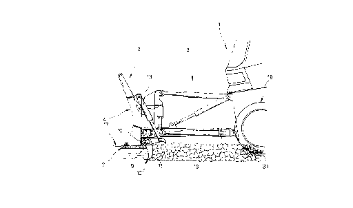
Fig. 1 shows a side view of the front part of a snow
grooming device with a rake blade according to
the present invention, one renovator tooth being
shown in the operating position and another one
in the stand-by position, and
Fig. 2 shows a top view of a rake blade with renovator
teeth and with two lateral, adjustable sliding
elements.
Fig. 1 shows the front section of a snow grooming device 1,
said front section having movably attached thereto a rake
blade 2 via a conventional multiple-joint bearing 3. The
rake blade 2 has all degrees of freedom of a conventional
rake blade.
According to Fig. 2, the rake blade 2 comprises a shovel 4
having, when seen in a top view, a U-shaped structural de-
sign. Said shovel consists of two U-legs 6 extending from
the sides of a U-base 5 such that they form an angle in the
direction of movement. At the front lower side of the rake
blade 2, a lower edge 7 is provided, which may be implement-
ed as a wavy edge over the width of the rake blade 2.

CA 022l0~39 l997-07-l~
-- 5
At the lower rear side of the rake blade 2, two shafts 9 are
arranged symmetrically to the longitudinal axis 8 of the ve-
hicle, said shafts 9 being connected to the rake blade 2 via
bearing blocks 10. Both shafts 9 project freely beyond the
U-base 5 and extend over the area of the U-legs 6.
The shafts 9 have arranged thereon uniformly spaced renova-
tor teeth 11, which are all arranged in a uniform sequence
in the direction of said shafts such that they are in align-
ment with one another. Each renovator tooth 11 has one of
its ends attached to a shaft 9. In Fig. 1 a renovator tooth
is shown at an approximately horizontal position (stand-by
position) on the one hand, and at an approximately vertical
position (fully extended operating position) on the other.
The renovator teeth 11 are steplessly adjustable between
these two positions.
The free end of each renovator tooth 11 is curved like a
claw, the curved side facing the ground at the stand-by
position and having at the end thereof a tip 12 that is
curved in the direction of movement.
Also a wedge-shaped element can, for example, be used as a
renovator tooth 11.
One renovator tooth 11 of each shaft 9 has attached thereto
a hydraulic cylinder/piston unit 13 as an adjustment device.
The other end of the cylinder/piston unit is supported in
the upper area on the back of the rake blade 2.
At the rear of each of the U-legs 6 extending at an angle, a
slide plate 14 is arranged as a sliding element, said slide
plate 14 being rotatably supported on the U-leg 6 via two
pivot bearings 15 and being secured in position on the rake
blade 2 via a transverse lever 16. At the floating position
of the rake blade, the slide plates 14 rest on the surface

~ CA 022l0~39 l997-07-l~
~ '
-- 6
17 of the piste.
In Fig. 1, it is shown how the renovator tooth 11, which is
located at the vertical operating position, engages the
piste leaving behind coarse clods 19 in the area between the
renovator tooth and ahead of the chains 18 of the snow
grooming device 1. The coarse clods 19 are crushed by said
chains 18 whereby smaller pieces 20 are formed.
In the following, the mode of operation of the snow grooming
device according to the present invention will be explained
in detail. At first, the two shafts g with the renovator
teeth 11 are located at the horizontal stand-by position.
The rake blade 2 is now lowered onto the surface 17 of the
piste until the slide plates 14 rest on said surface 17 and
until the lower edge 7 slightly penetrates into the surface
of the piste 17 when the snow grooming device is moving. At
this position, the rake blade 2 is operated at the floating
position and slides on the surface 17 of the piste.
For breaking up hard or icy pistes, the renovator teeth 11
can be pivoted to a lower level and lowered into the pist
via the cylinder/piston units 13. In this condition, they
tear up the piste foundation on a lower level and leave
coarse clods 19. The coarse clods are crushed by the stud
pins of the chains 18 following said renovator teeth 11.
The piste prepared in this way is then subjected to a fin-
ishing treatment with the aid of accessories, like snow
cutter means, which are attached to the rear end of the
vehicle.

Representative Drawing
A single figure which represents the drawing illustrating the invention.
Administrative Status

2024-08-01:As part of the Next Generation Patents (NGP) transition, the Canadian Patents Database (CPD) now contains a more detailed Event History, which replicates the Event Log of our new back-office solution.

Please note that "Inactive:" events refers to events no longer in use in our new back-office solution.

For a clearer understanding of the status of the application/patent presented on this page, the site Disclaimer , as well as the definitions for Patent , Event History , Maintenance Fee  and Payment History  should be consulted.

Event History

Description Date
Application Not Reinstated by Deadline 2000-10-27
Time Limit for Reversal Expired 2000-10-27
Inactive: Abandoned - No reply to s.30(2) Rules requisition 2000-02-24
Deemed Abandoned - Failure to Respond to Maintenance Fee Notice 1999-10-27
Inactive: S.30(2) Rules - Examiner requisition 1999-08-24
Inactive: IPC assigned 1997-10-09
Inactive: First IPC assigned 1997-10-09
Classification Modified 1997-10-09
Inactive: Acknowledgment of national entry - RFE 1997-09-25
Letter Sent 1997-09-25
Inactive: Applicant deleted 1997-09-23
Application Received - PCT 1997-09-23
All Requirements for Examination Determined Compliant 1997-07-15
Request for Examination Requirements Determined Compliant 1997-07-15
Application Published (Open to Public Inspection) 1996-07-25

Abandonment History

Abandonment Date Reason Reinstatement Date
1999-10-27

Maintenance Fee

The last payment was received on 1998-07-23

Note : If the full payment has not been received on or before the date indicated, a further fee may be required which may be one of the following

  • the reinstatement fee;
  • the late payment fee; or
  • additional fee to reverse deemed expiry.

Patent fees are adjusted on the 1st of January every year. The amounts above are the current amounts if received by December 31 of the current year.
Please refer to the CIPO Patent Fees web page to see all current fee amounts.

Fee History

Fee Type Anniversary Year Due Date Paid Date
MF (application, 2nd anniv.) - standard 02 1997-10-27 1997-07-15
Registration of a document 1997-07-15
Basic national fee - standard 1997-07-15
Request for examination - standard 1997-07-15
MF (application, 3rd anniv.) - standard 03 1998-10-27 1998-07-23
Owners on Record

Note: Records showing the ownership history in alphabetical order.

Current Owners on Record
KASSBOHRER GELANDEFAHRZEUG GMBH
Past Owners on Record
GERD FRIEDMANN
HELMUT KANZLER
Past Owners that do not appear in the "Owners on Record" listing will appear in other documentation within the application.
Documents

To view selected files, please enter reCAPTCHA code :


To view images, click a link in the Document Description column. To download the documents, select one or more checkboxes in the first column and then click the "Download Selected in PDF format (Zip Archive)" or the "Download Selected as Single PDF" button.

List of published and non-published patent-specific documents on the CPD .

If you have any difficulty accessing content, you can call the Client Service Centre at 1-866-997-1936 or send them an e-mail at CIPO Client Service Centre.


Document
Description 
Date
(yyyy-mm-dd) 
Number of pages   Size of Image (KB) 
Representative drawing 1997-10-15 1 10
Claims 1997-07-14 2 60
Description 1997-07-14 6 266
Abstract 1997-07-14 1 17
Drawings 1997-07-14 2 42
Reminder of maintenance fee due 1997-09-23 1 111
Notice of National Entry 1997-09-24 1 202
Courtesy - Certificate of registration (related document(s)) 1997-09-24 1 118
Courtesy - Abandonment Letter (Maintenance Fee) 1999-11-23 1 184
Courtesy - Abandonment Letter (R30(2)) 2000-04-05 1 171
PCT 1997-10-07 5 129
PCT 1997-07-14 13 431
Fees 1998-07-22 1 31