Language selection

Search

Patent 2210565 Summary

Third-party information liability

Some of the information on this Web page has been provided by external sources. The Government of Canada is not responsible for the accuracy, reliability or currency of the information supplied by external sources. Users wishing to rely upon this information should consult directly with the source of the information. Content provided by external sources is not subject to official languages, privacy and accessibility requirements.

Claims and Abstract availability

Any discrepancies in the text and image of the Claims and Abstract are due to differing posting times. Text of the Claims and Abstract are posted:

  • At the time the application is open to public inspection;
  • At the time of issue of the patent (grant).
(12) Patent Application: (11) CA 2210565
(54) English Title: METHOD OF FORMING A FIBROUS FILTER ELEMENT
(54) French Title: PROCEDE DE FABRICATION D'UN ELEMENT FILTRANT FIBREUX
Status: Deemed Abandoned and Beyond the Period of Reinstatement - Pending Response to Notice of Disregarded Communication
Bibliographic Data
(51) International Patent Classification (IPC):
  • B01D 39/14 (2006.01)
  • B01D 35/10 (2006.01)
  • B01D 46/24 (2006.01)
(72) Inventors :
  • COSGROVE, RONALD CHARLES (United Kingdom)
(73) Owners :
  • KALSEP LIMITED
(71) Applicants :
  • KALSEP LIMITED (United Kingdom)
(74) Agent: OSLER, HOSKIN & HARCOURT LLP
(74) Associate agent:
(45) Issued:
(86) PCT Filing Date: 1996-02-09
(87) Open to Public Inspection: 1996-08-15
Examination requested: 2003-01-31
Availability of licence: N/A
Dedicated to the Public: N/A
(25) Language of filing: English

Patent Cooperation Treaty (PCT): Yes
(86) PCT Filing Number: PCT/GB1996/000275
(87) International Publication Number: GB1996000275
(85) National Entry: 1997-07-16

(30) Application Priority Data:
Application No. Country/Territory Date
9502625.8 (United Kingdom) 1995-02-10

Abstracts

English Abstract

In a fibrous filter element in which there are a bundle of fibres having woven edges supported around an inner support such as a cylinder and attached between two end supports the woven edges of the bundle of fibres are encapsulated with the end support with an encapsulating resin, this avoids the packing density of the fibres at the end of the element being reduced compared to that at the centre of the element and makes for easier handling and manufacture.


French Abstract

L'invention concerne un élément filtrant fibreux comportant un faisceau de fibres à bords tissés maintenu autour d'un support intérieur, tel qu'un cylindre, et fixé entre deux supports d'extrémité, les bords tissés du faisceau de fibres étant enrobés avec le support terminal avec une résine d'enrobage, ce qui permet d'éviter une réduction de la densité de compactage des fibres à l'extrémité de l'élément filtrant en comparaison de celle obtenue au centre de l'élément et ce qui en facilite la manipulation et la fabrication.

Claims

Note: Claims are shown in the official language in which they were submitted.

Claims
1. A fibrous filter element which comprises a bundle of fibres provided with
an inner support means and attached between two end supports, the bundle
of fibres having woven edges at the point of attachment to the end supports
and in which the woven edges of the bundle of fibres are encapsulated with
the end support with an encapsulating resin.
2. A fibrous filter element as claimed in claim 1 in which the woven edges
of the bundle of fibres are attached to the end supports by means which
can hold the edges in position when they are encapsulated.
3. A fibrous filter element as claimed in claim 2 in which the means which
can hold the edges in position are metal or fibrous hooks.
4. A fibrous filter element as claimed in claim 3 in which the means which
can hold the edges in position are metal hooks arranged substantially
concentrically around the bundle of fibres.
5. A fibrous filter element as claimed in any one of the preceding claims in
which the inner support member is a perforated cylinder or a helical spring.
6. A fibrous filter element as claimed in any one of the preceding claims in
which the encapsulating resin is a resin which can set to form a
liquid-impervious strong bond between the end plate and the edge of the bundle
of fibres.
7. A fibrous filter element as claimed in claim 6 in which the encapsulating
resins is a is polyurethane, an epoxy resin or a thermoplastic resin
8. A fibrous filter element as claimed in claim 7 in which the epoxy resin is
a two part epoxy resin.

9. A fibrous filter element as claimed in claim 1 as described in the
drawings.
10. A method of forming a fibrous filter element as claimed in any one of
the preceding claims which method comprises attaching the woven edges of
the bundle of fibres to the end supports, winding the bundle of fibres
around the support member and encapsulating the attached woven edges of
the bundle of fibres with the end supports by immersion in the
encapsulating resin.
11. A method of forming a fibrous filter element as claimed in claim in
which the encapsulation is carried out by placing the encapsulating resin in
a mould, immersing the end of the element in the mould and setting the
resin.

Description

Note: Descriptions are shown in the official language in which they were submitted.


CA 02210~6~ 1997-07-16
WO 96124428 PCT/GB96100275
Method of Forming a Fibrous Filter Element
The present invention relates to a method of forming a fibrous filter element
suitable for use in apparatus used for filtering solids from liquids or for
coalescing droplets of one liquid dispersed in another liquid.
EP 0 004 724 discloses an apparatus for removing ~o"l~",;"~"l~ from a
liquid which comprises bundles of fibres aligned parallel to one another
between two end plates. The end plates may be moved axially to stretch or
compress the fibres. Liquid flows through the apparatus parallel to the
fibre bundles.
EP 0 207 797 discloses another apparatus for removing cont~min~ntc from
a liquid. This al~pa~ s also comprises fibres connected at each end to end
supports, which end supports can be moved away from or towards each
other to place the fibres under tension or to relax any applied tension. The
end supports can also be rotated relative to each other and an inner cylinder
is used as support for the fibrous filter element.
EP 360 601 discloses another similar apparatus in which a helical spring
replaces the cylinder to support the fibrous filter element.
In each of these arrangements the fibrous element comprises bundles of
fibres attached to end supports. The filter element contains top and bottom
woven edges with single fibre threads in between. The element is wound
around the inner cylinder or spring and the woven edges are suitably seated
to the end supports or may preferably be coated with adhesive and then
wound onto the cylinder.
In either method, the procedure ensures that the filter element is sealed and
secured to the end supports and with~t~n~c the stresses associated

CA 02210~6~ 1997-07-16
WO 96/2~28 PCTtGB96/00275
with the operation of the element as the fibres are twisted and compressed.
To f~cilit~te the operation of the filter element, metal end plates are
required; these have to be added to the filter assembly resulting in costly
m~--.hining and assembly operations.
The present invention obviates the need for this, resulting in reduced cost
and reduced weight which makes for easier h~n-llinsg and servicing.
Another problem associated with existing methods of securing the filter
element to the end supports is that the ends of the element in the area of
,~çhment to the end supports tend to be bulky due to the thickness of the
adhesive layers, even when a miniml-m quantity of adhesive is used. This
results in the packing density of the fibres at the end of the element being
reduced colllpal ed to that at the centre of the element, resulting in
channelling and reduced p~:-r~,-l--a--ce. In order to reduce this effect, it hasbeen necessary to pack the element more tightly, resulting in a higher
Te- e..Lial pressure across the filter and hence higher operating costs.
We have now found that by chemically encapsulating the bundle of fibres
with the end supports, these disadvantages may be reduced.
The present invention provides a fibrous filter element which comprises a
bundle of fibres provided with an inner support means and attached
between two end supports, the bundle of fibres having woven edges at the
point of ~tt~hmt~nt to the end supports and in which the woven edges of
the bundle of fibres are encapsulated with the end support with an
encapsulating resin.
The woven edges of the bundle of fibres can be ~tt~rhed.to the end
supports by any suitable means, for example, by metal hooks~ fibrous hooks
or other means which can hold the edges in position when they are
encapsulated.

CA 02210~6~ 1997-07-16
wo 96/24428 PCT/GB96/0027
When metal hooks are used they can be arranged concentrically around the
bundle.
The structure of the present invention can be formed by ~tt~chin~ the
woven edges of the bundle of fibres to the end supports, winding the bundle
of fibres around the support member and encapsulating the attached woven
edges of the bundle of fibres with the end supports by immersion in an
encapsulating resin.
Suitable encapsulating resins include those which are inert to the liquids
passing through the filter element and which set to form a liquid-
impervious strong bond between the end plate and the edge of the bundle
of fibres.
Suitable encapsulating resins are chemical potting compounds such as
polyureth~nes, epoxy potting compounds and thermoplastic resins such as
hot melt plastics.
Suitable epoxy compounds are sold under the trade name "Permabond",
e.g. two part epoxy resins and are widely available.
The encapsulation can be carried out by placing the encapsulating resin in a
suitable mould, h~ ing the end of the element in the mould and setting
the resin.
The inner support member can be a perforated cylinder, helical spring or
other support melllbel.
The fixing means and structure of the present invention can be used inassociation with existing fibrous filter structures. such as those described in
EP 0 004 724, EP 0 207 797 and EP 360 601.
It is a feature of the present invention that the stresses encountered with
prior art structures are reduced and are more evenly distributed and

=
CA 02210~6~ 1997-07-16
WO 96/24428 PCT/GB96/00275
more of the stresses are l-~n~ ed from the fibre bundle to the end
supports, avoiding excess stress in the encapsulating resin.
i
Another feature is that the present invention produces a structure which is
considerably lighter, easier and cheaper to produce and m~int~in than
structures using prior art methods and also is less prone to degradation and
has a longer life.
The invention will now be described with reference to the accompanying
drawings in which:-
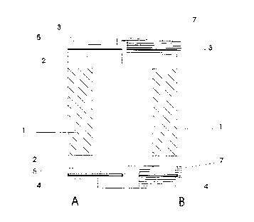
Fig. 1 is a plan view of a filter element showing a half section of theelement before and after encapsulation and
Fig. 2 is a side view of the filter element
Referring to the drawings side A of the drawings shows the filter element
before encapsulation and side B shows the filter element after
encapsulation. The fibrous filter element comprises a bundle of fibres (1)
having woven edges (2) in the plox~ y of the end supports (3) and (4).
Hooks (5) are used to attach the edges (2) to the end supports (3) and (4)
and the hooks (5) are arranged concentrically (6) around the bundle of
fibres.
The ends (3) and (4) with the woven edges (2) ~tt~hed are contacted with
an epoxy resin "Permabond 3030" by placing the ends in a suitably shaped
mould and pouring the resin around the ends. The resin is then hardened
around the end to form an integrally sealed filter element (7) with a uniform
arrangement of the fibres.
Thus the present invention enables a sealed, light weight, strong permanent
~tt~chment for the ends of the fibrous element to be obtained.

Representative Drawing
A single figure which represents the drawing illustrating the invention.
Administrative Status

2024-08-01:As part of the Next Generation Patents (NGP) transition, the Canadian Patents Database (CPD) now contains a more detailed Event History, which replicates the Event Log of our new back-office solution.

Please note that "Inactive:" events refers to events no longer in use in our new back-office solution.

For a clearer understanding of the status of the application/patent presented on this page, the site Disclaimer , as well as the definitions for Patent , Event History , Maintenance Fee  and Payment History  should be consulted.

Event History

Description Date
Inactive: Agents merged 2013-10-24
Inactive: IPC from MCD 2006-03-12
Application Not Reinstated by Deadline 2005-02-09
Time Limit for Reversal Expired 2005-02-09
Deemed Abandoned - Failure to Respond to Maintenance Fee Notice 2004-02-09
Letter Sent 2003-02-25
Request for Examination Received 2003-01-31
All Requirements for Examination Determined Compliant 2003-01-31
Request for Examination Requirements Determined Compliant 2003-01-31
Inactive: First IPC assigned 1997-11-17
Inactive: IPC assigned 1997-11-17
Inactive: Single transfer 1997-11-10
Classification Modified 1997-10-22
Inactive: Courtesy letter - Evidence 1997-09-30
Inactive: Notice - National entry - No RFE 1997-09-25
Inactive: Applicant deleted 1997-09-24
Application Received - PCT 1997-09-24
Application Published (Open to Public Inspection) 1996-08-15

Abandonment History

Abandonment Date Reason Reinstatement Date
2004-02-09

Maintenance Fee

The last payment was received on 2003-01-31

Note : If the full payment has not been received on or before the date indicated, a further fee may be required which may be one of the following

  • the reinstatement fee;
  • the late payment fee; or
  • additional fee to reverse deemed expiry.

Patent fees are adjusted on the 1st of January every year. The amounts above are the current amounts if received by December 31 of the current year.
Please refer to the CIPO Patent Fees web page to see all current fee amounts.

Fee History

Fee Type Anniversary Year Due Date Paid Date
Basic national fee - standard 1997-07-16
Registration of a document 1997-11-10
MF (application, 2nd anniv.) - standard 02 1998-02-09 1997-11-19
MF (application, 3rd anniv.) - standard 03 1999-02-09 1999-01-22
MF (application, 4th anniv.) - standard 04 2000-02-09 2000-02-08
MF (application, 5th anniv.) - standard 05 2001-02-09 2001-02-06
MF (application, 6th anniv.) - standard 06 2002-02-11 2002-01-24
MF (application, 7th anniv.) - standard 07 2003-02-10 2003-01-31
Request for examination - standard 2003-01-31
Owners on Record

Note: Records showing the ownership history in alphabetical order.

Current Owners on Record
KALSEP LIMITED
Past Owners on Record
RONALD CHARLES COSGROVE
Past Owners that do not appear in the "Owners on Record" listing will appear in other documentation within the application.
Documents

To view selected files, please enter reCAPTCHA code :


To view images, click a link in the Document Description column. To download the documents, select one or more checkboxes in the first column and then click the "Download Selected in PDF format (Zip Archive)" or the "Download Selected as Single PDF" button.

List of published and non-published patent-specific documents on the CPD .

If you have any difficulty accessing content, you can call the Client Service Centre at 1-866-997-1936 or send them an e-mail at CIPO Client Service Centre.


Document
Description 
Date
(yyyy-mm-dd) 
Number of pages   Size of Image (KB) 
Representative drawing 1997-11-18 1 7
Description 1997-07-15 4 147
Abstract 1997-07-15 1 49
Drawings 1997-07-15 1 20
Claims 1997-07-15 2 50
Notice of National Entry 1997-09-24 1 193
Reminder of maintenance fee due 1997-10-11 1 111
Courtesy - Certificate of registration (related document(s)) 1998-03-19 1 118
Reminder - Request for Examination 2002-10-09 1 115
Acknowledgement of Request for Examination 2003-02-24 1 185
Courtesy - Abandonment Letter (Maintenance Fee) 2004-04-04 1 175
PCT 1997-07-15 9 306
Correspondence 1997-09-29 1 31
Fees 2003-01-30 1 43
Fees 2002-01-23 1 53
Fees 1999-01-21 1 58
Fees 2000-02-07 1 54
Fees 1997-11-18 1 55
Fees 2001-02-05 1 55