Note: Descriptions are shown in the official language in which they were submitted.
' CA 02210704 1997-07-17
W O 96/24235 1~1/r~ ~0005~
Arrangement for attaching an electrical component to a
mounting base
The invention relates to an arrangement for
attaching an electrical component to a mounting base and
for connecting it galvanically to a terminal block
connected to the mounting base. The arrangement of the
invention is particularly suitable for use with
components carrying higher currents, for example
inductive components such as measuring transformers.
If the mounting base is a printed board,
various soldering techniques are typically employed for
attaching electrical components mechanically to the
mounting base and for connecting them electrically to
the terminal block ~connected to the mounting base.
However, such techniques cannot be employed with higher
currents, since the cross-sectional area of copper foil
strips on conventional printed boards is not sufficient
for conducting such currents. A typical example of a
component carrying- higher currents is a measuring
transformer. In the following, known solutions will be
dealt with particularly in the case of measuring
transformers.
Transformers implemented as laminated core
transformers are typically attached to the mounting base
by iron binders which are secured to the base either by
screws or other mechanical fasteners, such as rivets,
or by bending the ends of the iron binders so that they
attach the transformer mechanically to the base. The
terminals for the primary and secondary winding in the
transformers are provided by unfixed conductors. This
conventional securing technique involves the laborious
step of securing the iron binders. Providing the
terminals in the transformers by unfixed conductors, in
turn, entails the possibility of faulty coupling; in
CA 02210704 1997-07-17
W096/24~S PCT ~ ~05S
addition, it is very difficult to check the coupling
visually, particularly if the there are seyeral
measuring transformers on the base, which is often the
case.
In the same way as a laminated core trans-
former, it is possible to attach a toroidal transformer
mechanically to the base either from its case or by a
fastening means screwed through its centre. Even in this
case, the terminals for the primary and secondary
winding are provided by unfixed conductors. A toroidal
transformer is thus not different from a laminated core
transformer as regards the problems associated with the
securing and coupling.
One alternative is to attach the transformer
to a printed board from solder-tags and to provide the
wiring by means of copper foil strips on the printed
board. This printed board solution is, however, often
uneconomic, since the copper foil strips must be made
thicker than usual in order to provide conductors with
a sufficient cross-sectional area. Moreover, the
requirements set by the norms for the current-carrying
capacity are not met if soft soldering is used.
Transformers which are moulded in plastic and
in which terminals are soldered to the ends of the
primary windings are also used to some extent in the
field. However, moulding transformers in plastic
requires large series, and because of the many different
combinations, the production control and storage incur
extra costs. The more there are transformers, the more
difficult it is to mount them on a base and to provide
a compact construction.
It should also be noted that in the case of
measuring transformers it is necessary to apply the norm
DIN 57435, concerning static measuring and protection
relays. According to this norm, the requirement for
CA 02210704 1997-07-17
W096~24~5 PCT ~ 6/~OSS
continuous current-carrying capacity is a quadruple
nominal current, the requirement for continuous thermal
current-carryi~g capaclty for one second is a
hundredfold nominal current, and the requirement for
dynamic current-carrying capacity is 2,5-fold thermal
current-carrying capacit~ for one half-cycle. If the
nominal current is, for example, 5 A, the requirement
for continuous thermal current-carrying capacity grows
to 500 A for 1 s, and the requirement for dynamic
current-carrying capacity grows to 12SO A.
The object of the present invention is to
provide a new type of solution for attaching electrical
components, particularly inductive components such as
measuring transformers, to a mounting base, and for
wiring their primary circuit rapidly and without the
possibility of faulty coupling. This is achieved with
an arrangement of the invention, which is characterized
in that the terminal block comprises a first contact
piece of a plug-in connector, and the component
comprises a second ~contact piece of the plug-in
connector, and that the component and the mounting base
comprise interlocking parts for attaching the component
to the base, whereby when the component is locked to the
base, the contact pieces of the plug-in connector
provide a galvanic contact between the component and the
terminal block.
When the arrangement of the invention is
applied, the transformers are thus locked mechanically
to the base by means of snap-in-type locking means, as
the transformers and the mounting base are provided with
elements which interlock with each other. Such a
mechanical locking also provides an electrical contact
between the contact piece of the terminal block
connected to the mounting base and the complementary
contact piece attached to the electrical component. The
;
CA 02210704 1997-07-17
W 096)2423S l~l~.U0005S
terminal block preferably comprises the male contact
piece of the plug-in connector, whereas the electrical
component comprises its female contact piece. It is thus
possible to encase the female contact piece neatly in
the frame of the component. The male contact piece can
be easily shaped as a bus bar, which is guided to a
groove reserved for;it when the terminal block module
is mounted.
When a plurality of electrical components are
attached to a mounting base in the arrangement of the
invention, the components are preferably arranged on the
mounting base in two or more rows so that the components
in these rows are interposed with respect to each other,
and each terminal block preferably comprises two contact
pieces: a first one at the first row of components and
a second one at the second row of components. This
arrangement makes the construction compact and
eliminates the possibility of faulty coupling. In
addition, electrical coupling to a component in either
the first or the second row can be performed by means
of a similar terminal block. It is therefore necessary
to have terminal blocks of only one kind, which is
clearly an advantage in view of rationalization.
When the electrical component is a measuring
transformer, the gaIvanic contact between the terminal
block and the component preferably comprises a contact
with the primary winding of the measuring transformer.
The primary winding is the part of the measuring
transformer where the strength of the current is several
amperes, and thus the current cannot be conducted
through copper foil strips of conventional printed
boards, especially lf the above-mentioned requirements
set by DIN 57435 for the current-carrying capacity are
taken into account.
In the following, the arrangement of the
CA 02210704 1997-07-17
WO 96124235 1 ~_l/r ~~OOOSS
invention will be described in greater detail with
reference to the accompanying drawings, in which
Figure 1 is a perspective view of an
illustrative embodiment of a base suitable for use in
the arrangement of the invention and of an illustrative
embodiment of a terminal block to be connected to it,
Figure 2 is a cross-section of the terminal
block shown in Figure 1,
Figure 3 is a perspective view of the
arrangement of Figure 1 when the terminal blocks have
been attached to the mounting base and the electrical
components are being attached thereto, and
Figure 4 is a more detailed view of the
electrical component and its electrical coupling to the
contact piece of the terminal block.
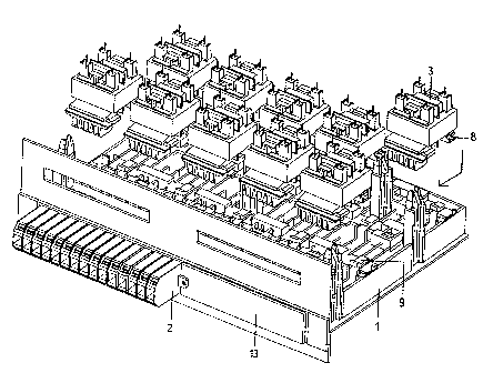
Figure 1 is a perspective view of an
illustrative embodiment of a mounting base suitable for
use in the arrangement of the invention. The mounting
base comprises a plurality of compartments or recesses
into which the electrical components can be pressed so
that the shape of the mounting base guides each
component to its correct place. The base is provided
with a plurality of locking tongues or the like 9, by
means of which the components are locked in place after
being pressed into their final positions on the base.
To enable such a snap-in-type locking, the electrical
component is naturally provided with a suitable
counterpart for receiving the locking tongues. The
mounting base 1 and the electrical component are also
provided with other cooperating parts which guide the
component to its correct position on the mounting base.
In this application, such cooperating parts and the
snap-in-type locking tongues or corresponding locking
means provided in them will be called interlocking
parts. Interlocking parts of this kind, which are
CA 02210704 1997-07-17
WO96124235 1~,1/rL,~5.~0005S
-
indicated in the drawings by way of an example by
reference numerals 8 and 9, also guide the component
when it is pressed into its place and lock it in its
desired final position. The purpose of the interlocking
parts and the locking means is to support the components
and to lock them onto the mounting base so firmly that
the components are not detached under any mechanical
stresses.
Figure 1 further shows an illustrative
embodiment of terminal blocks 2 to be connected to the
edge of the mounting base 1. In Figure 1, the terminal
blocks 2 form a terminal block module intended for a
plurality of electrical components. The terminal block
module illustrated in Figure 1 is suitable for
connecting five measuring transformers, since one
measuring transformer requires three terminal blocks.
To facilitate the mounting, the terminal blocks have,
however, been combined to form larger terminal block
modules (comprising e.g. 15 terminals as in Figure 1),
which are also locked to the edge of the mounting base
by means of snap-in-type locking tongues. These locking
tongues can be seen in Figure 1, where they are
indicated by reference numerals 11. Locking tongues are
provided both above and below the terminal blocks for
locking the terminal block module reliably in its place.
For connections to be made at its end facing
the base, the terminal block 2, shown in cross-section
in Figure 2, comprises a bus bar 5 with two flat male
contacts 4 and 6. When the terminal block of Figure 2
is pushed into its~place at the edge of the mounting
base 1, the bus bar 5 is placed in a groove provided in
the mounting base so that the contact pieces 4, 6 remain
visible to allow an electrical connection to be made to
one of them. The conductor which carries the signal to
be measured to the terminal block 2 is connected in a
,
CA 02210704 1997-07-17
W 096124Z35 ~llr~'~000SS
conventional manner by means of a connection screw to
a contact strip 12 disposed within the case of the
~ terminal block. A current or voltage signal to be
measured is thus applied to these terminal blocks.
~ 5 In the case illustrated in Figure 3, the
terminal block module is inserted in its place at the
edge of the mounting base 1, and the other end of the
space reserved for terminal blocks is covered with a
covering plate 13. Figure 3 also shows a number of
measuring transformers 3 to be attached to the mounting
base. As stated above, the terminal block module shown
in the figure is sufficient for connecting only five
measuring transformers; in practice, these would be the
five transformers farthest on the left in Figure 3,
three of them in the front row, i.e. the row closer to
the front panel, and two in the back row. As shown in
Figure 3, a measuring transformer is attached to the
mounting base 1 by bringing it at first to the correct
position above the mounting base and by pressing it then
into the correct place on the mounting base so that the
cooperating parts of the mounting base and the measuring
transformer interlock with each other. Thereafter the
measuring transformer 3 is pushed towards the terminal
block 2, whereby the locking means lock the measuring
transformer 3 in its place; at the same time, an
electrical contact is formed between the contact piece
7 of the measuring transformer 3 and the contact piece
4 or 6 of the terminal block 2. This is illustrated in
greater detail in Figure 4.
Figure 4 shows an illustrative embodiment of
a measuring transformer suitable for use with a mounting
base of the invention. The coil former illustrated
differs from a conventional one in that it comprises
parts, or attachment lugs 8, interlocking with the
mounting base 1 for attaching the transformer thereto.
CA 02210704 1997-07-17
W096/~S PCT ~ 6/0005S
The manufacture of a measuring transformer according to
Figure 4 comprises the steps of winding a secondary
winding onto a coil former, and soldering its ends 14
to solder lugs 15 positioned at the end of the coil
former opposite to the attachment lugs. In order to wind
the two primary windings of the transformer, the wires
needed for each primary winding are at first cut, and
their ends are provided with crimp terminals 7 in such
a way that one end of each wire is inserted into a crimp
terminal 7 common to all the windings. Subsequently, the
first terminal is pushed into a space provided for it
in the coil former, and is snappingly locked in its
place. The first wlnding portion is thereafter wound,
and the contact con~necting the first and the second
winding portion is positioned in the space provided for
it. The second winding portion is then wound, and the
third contact is inserted in its place in the same way
as the two preceding ones. Subsequently, the E/I
transformer plates 16 are piled up, and the transformer
is varnished. At this stage, the transformer is in the
form shown in Figure 4 and ready to be inserted in its
place on the mounting base.
When a transformer is inserted in its place,
the attachment lugs of the coil former are pressed into
corresponding grooves on the mounting base, and the
transformer is moved a few millimetres towards the
terminal block 2, whereby an electrical contact is
formed between the female contacts 7 in the transformer
and the contacts 6 connected to the bus bars 5 of the
terminal blocks. In this case, the transformer is
connected to the second row, i.e. to the row further
from the front panel. If the transformer were positioned
in the row which is closer to the front panel, it would
be connected to the contact piece 4 of the terminal
block 2.
CA 02210704 1997-07-17
W096l24~5 ~ ~6/~S5
;
As can be seen from Figure 3, the transformers
in the first and the second row are interposed with
respect to each other. This saves room on the mounting
base, and in addition, helps to avoid faulty con-
nections, as it is not;possible to connect a transformer
to both contact pieces 4 and 6 of the terminal block 2
at the same time.
Of measuring transformers, current transformers
are those whose primary windings carry a higher current,
wherefore they are mounted using the arrangement of the
invention. They must therefore be mounted either in the
first or in the second row from the front panel. Voltage
transformers, in turn, can be mounted in any row, i.e.
in the first or second row, or in the third row, which
lS is not connected to the terminal blocks 2. The
connections of both the primary and the secondary
windings of the voltage transformers to be mounted in
the third row are made through solder peaks 17 which can
be seen on top of the transformers. In practice, this
is performed in such a way that after the transformers
have been locked onto the base, a printed board with
through holes for the solder peaks is placed on top of
the transformers 3, and the solder peaks are soldered
in a conventional manner to the copper foil strips on
the printed board. This procedure is followed with the
connections of the secondary windings of the voltage and
current transformers ln both the first and the second
row, and with the connections of both the primary and
the secondary windings of voltage transformers in the
third row, since the currents in these windings are so
low that they can be conducted through copper foil
strips of the printed board.
The arrangement of the invention allows a
combination of measuring transformers needed for each
specific case to be manufactured extremely simply,
- . =
CA 02210704 1997-07-17
W 096/24235 1~lir~.~0005S
reliably and rapidly. The correct mounting of the
measuring transformers can be easily ensured by
providing the measuring transformers with clearly
visible indications of their type. No other information
is needed, as the terminals of both the primary and the
secondary winding are located in their fixed places in
the coil former.
In the above, the arrangement of the invention
has been described by way of an example with reference
to only one embodiment. It will be understood that, as
regards the appearance, the invention can be modified
even significantly according to the electrical component
to be used without departing from the scope of
protection defined by the appended claims or from the
basic idea of the invention, according to which
components are locked to a mounting base by mechanical
interlocking parts, and at the same time as the
mechanical locking takes place, an electrical contact
is also formed between a first contact piece in the
component and a second contact piece on the mounting
base.