Note: Descriptions are shown in the official language in which they were submitted.
CA 02210931 1997-07-18
DOORJAMB ASSEMBLY WITH EXTRUDED UNITARY MOLDING
AND STOP M~MR~RS
FIELD OF THE INVENTION
This invention relates generally to door or window jamb
assemblies used to frame openings in the walls of buildings for
receiving doors and windows. More specifically, the invention
CA 02210931 1997-07-18
relates to an imprcved door jamb assembly wherein .he framing
members of the assembly are formed from unitary extruded
thermoplastic molding and stop members mounted .o elongated
wooden support members.
.
BACKGROUlnD OF THE I ~ ENTION
In constructing a building such as a house, it is common
that openings for receiving doors and windows are first roughly
framed in with wall studs, which usually are made of wood.
Subsequently, the rough framed openings are finisred with a
wooden door or window jamb assembly, which often is provided with
a decorative brickmold that abuts the brick or sicing on the
outside of the building. In some instances, the brickmold is
milled as an integral part of the jamb frame members and in other
i5 instances the brickmold is nailed or stapled to the jamb members
along their outside edges. In door jamb assemblies in
particular, a peripheral lip or stop usually is milled into the
wooden support members of the jamb and the stop extends around
the inner periphery of the jamb. In use, a closed door mounted
to the jamb assembly rests against the stop. In many instances,
the stop bears a weather strip that seals against the closed door
to prevent drafts.
CA 02210931 1997-07-18
In sidelight door jamb assemblies, a pair of spaced vertical
mullions extend between the sill and the header of the assembly
to form a central opening for receiving a hinged door and a pair
of narrow side openings on either side of the door for receiving
sidelight windows. Such mullions typically are formed~of a pair
of back-to-back wooden supports that have been milled along their
exposed faces to provide stops for abutting a closed door or
receiving and securing the sidelight windows. A strip of
decorative molding is commonly nailed along the outside edges of
the mullion supports to cover their outside edges, to cover the
junction between the supports, and to lend a pleasing appearance
to the jamb assembly.
A traditional method of fabricating a door jamb assembly is
to mill the peripheral support members of the assembly from
larger pieces of a high quality clear wood. In this process, a
relatively wide thick piece of wood for each leg of the assembly
is passed through a milling machine and unwanted portions are cut
or milled away and discarded as sawdust. The milling process
produces the raised inside peripheral stops and other st-ructural
features of the support members. Obviously, this process is
wasteful and is becoming more and more expensive in light of the
ever-increasing cost of lumber. In some instances, the entire
CA 02210931 1997-07-18
cross-section of each frame member, including the br-ckmold, is
milled as a unitary piece from a wiae thick piece of lumber. In
other instances, the frame members are milled from two pieces of
wood that fit together to define the finished jamb shape. The
S inner peripheral supports may be milled from relatively thinner
pieces of wood to define the frame and door stop and the
brickmold may be nailed along the outer edges of the supports to
define the finished shape of the jamb. In either case,
significant amounts of expensive lumber are required as is time
consuming, expensive, and waste_ul machining steps. All of this
adds to the final cost of traditional door jamb assemblies.
Further, and perhaps even more pertinent, is the fact that the
exposed wooden brickmoid and the molding along the mullions of
side light door jamb assemblies reauires periodic painting and
maintenance in order to prevent rotting as a result of exposure
to the weather. Even with the most careful maintenance, these
exposed wooden portions of door jamb assemblies can, over time,
begin to rot from within whereupon the entire door jamb assembly
usually must be replaced.
Door and window jamb assem~iies have been developed that are
wholly or partially comprised of extruded thermoplastic portions.
For example, U.S. Patent No. 1,030,830 to Sailor teaches a jamb
CA 02210931 1997-07-18
for mounting a window or door in an opening of an existing
structure. The jamb includes an extruded plastic or metal outer
frame comprising the stop, a wooden inner frame or jamb for
support of the extruded outer frame, fasteners for attaching the
outer frame at the window or door opening, and a molded cover
that secures the outer frame and conceals the ~asteners attaching
the frame to the structure. In Sailor, the portion of the
plastic outer frame forming the stop and brickmold are hollow and
thus may not provide sufficient strength to the frame. The
hollow nature of the brickmold makes it unsuitable for receiving
standard nails that hold the assembly to the frame. Non-
carpentry standard fastening means are thus employed, which is
distasteCul to many carpenters. In addition, this jamb assembly
requires the use of an auxiliary cover to conceal the fasteners
attaching the frame to the building structure.
U.S. Patent No. 5,058,323 to Gerritsen teaches a jamb
cladding and brickmold assembly that provides a plastic member
that either wraps around a wooden jamb with a milled stop or that
wraps around a wooden jamb and provides its own plastic stop. An
attachable brickmold is also included. This assembly, like that
taught by Sailor, has hollow portions unsuitable for holding
nails and liable to be punctured or otherwise deformed by heavy
CA 02210931 1997-07-18
use or forcible contact. U.S. Patent No. 5,182,880 to Berge,
Jr., et al., teaches a cladding and brickmold apparatus similar
to that taught by Gerri tse~ in that it wraps around a combination
wooden jamb and stop. Thus, this device requires the use of a
wooden jamb with stop ana requires that the wood be~milled to
form the stop. The prior art does not teach a unitary stop and
brickmold assembly made of substantially solid extruded
thermoplastic material.
SUMMARY OF THE INVENTION
Briefly described, the present invention, in a preferred
embodiment thereof, comprises a door jamb assembly having a
substantially flat peripheral inner frame preferably formed of
wood. Each section of the frame is provided with a unitary
brickmold and stop member formed from substantially solid
extruded thermoplastic material. In the preferred embodiment,
the peripheral inner frame is formed from relatively thin flat
wooden boards to provide a traditional looking surface and to
provide a solid material for receiving nails and screws when
mounting the jamb and hanaing a door from the jamb. The
brickmold and stop members are extruded from appropriate
thermoplastic material to have a cross-sectional configuration
CA 02210931 1997-07-18
that forms both the stop of the jamb assembly ar.d the brickmold
that frames the assembly on the outside of a buildirg s.ructure.
More particularly, the brickmold.and stop members are formed with
a leg that at least partially overlies the inside faces of the
frame members and that defines a raised inner perlpheral stop
against which a closed door rests. The brickmold and stop
members are also formed to define a decorative brickmold portion
that frames the jamb on the outside of the building in which the
jamb is installed. The extruded brickmold and stop members are
adhered or otherwise firmly mounted to the wooden frame members
so that together they form a traditional looking door jamb and
brickmold assembly.
The brickmold and stop members are co-extruaed from a
thermoplastic material and preferably have a relatively less
dense blown thermoplastic core covered by a relatively more dense
plastic outer skin or covering. The density of the blown core is
sufficient to receive and hold a traditional finishing nail so
that the assembly can be nailed in place through the bric~mold in
the traditicnal way. In one embodiment, the brickmold is co-
extruded with a relatively hard plastic flange or tab thatprojects outwardly from the assembly and that is positioned to
overlie the outside surface of the building. During
CA 02210931 1997-07-18
installation, the assembly is positioned with the flanges against
the outer wall of the building and the assembly and flange are
fastened with nails cr screws. Brick, iap board, or another
exterior finish can then be applied over the flange and abutting
the brickmold to resu t in a traditional looking exterior door
molding arrangement. In the preferred embodiment, the extrusion
is also formed to def-ne a groove or slot that extends along the
stop of the assembly or receiving and holding the mounting tab
of a length of weather stripping.
In another embcdiment of this invention, the decorative
brickmold has an expoced outer surface and an inner surface that
is formed to define - recess. A stabilizer member, such as a
strip of wood, is diaposed in the recess for stabilizing the
brickmold and for prcviding a more secure medium through which
~attaching nails can ex_end. A short tab is co-extruded with the
brickmold and stop assembly and the tab extends partially over
the outside face of ~he wooden support member. Staples can be
driven through the tab and into the wooden support member to
attach the brickmold and stop member to the support member. In
one embodiment, the i-side face of the wooden support member is
milled with a recessed dado and the brickmold and stop member is
provided with a projection sized to be disposed in the recessed
CA 02210931 1997-07-18
dado. Staples can be driven through the projection and into the
wooden support member for attachment of the brickmold and stop
member to the support member.
In still another embodiment of the present invention, the
mullions of a side light door jamb assembly are each-f~rmed from
a back-to-back frame or support member. A generally U-shaped
extruded thermoplastic molding and stop member is secured to the
support members along the outside edges thereof. The legs of the
molding and stop member overlie a portion of the exposed faces of
the support members and form elongated stops that extend along
the length of the mullions intermediate the inside and outside
edges thereof. The bight portions of the molding and stop
members covers the outside edges of the support members and
provides a decorative appearance to the outside exposed portions
of the mullions. The stop formed along one side of the mullion
abuts a closed door mounted in the door opening of the jamb
assembly and the stop along the other side of the mullion
provides a surface against which side light windows can be
mounted in the assembly. In one embodiment, the exposed faces of
the mullion support members are milled with recessed dados
extending along their lengths and the extruded molding and stop
members are provided with projections that extend into the milled
g
CA 02210931 1997-07-18
recesses to hold the molc ng and stop member in place on the
mullion suppor~ members. ~ails or staples can be driven through
the projections if desired and into the support members to hold
the molding and stop members in place.
Thus it is seen that an improved door jamb assembly is now
provided wherein the need to mill or otherwise machine the stops,
molding, and other portions of the jamb is eliminated. A
relatively inexpensive thir flat board is used to form the inner
peripheral jamb or frame of the assembly. The stop members and
decorative molding portions of the jamb assembly are formed from
unitary thermoplastic co-extrusions that look, feel, and hold
nails li~e wood but that require substantially less maintenance
than wood and are not subject to rot or deterioration as is wood.
The jamb assembly of this -nvention can be installed with finish
nails in the same way as a ~raditional wooden assembly. This is
an advantage to carpenters, who prefer traditional installation
methods to new or complex alternate methods. These and many
other objects, features, and advantages will become more apparent
upon review of the detailed description set forth be-ow taken in
conjunction with the acccmpanying drawings which are briefly
described as follows.
CA 02210931 1997-07-18
BRIEF DESCRIPTION OF THE DRAWINGS
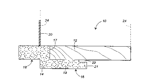
Fig. 1 is a cross-sectional view of a door jamb and
brickmold assembly that embodies principles of the present
invention in a preferred form.
5Fig. 2 is a cross-sectional view of a door jamb and
brickmold assembly that embodies principles of the present
invention in an alternate form.
Fig. 3 illustrates the configuration of a typical side light
door jamb assembly wherein vertically extending mullions form the
door and side light window openings of the assembly.
Fig. 4 is a cross-sectional view of a door jamb and
brickmold assembly that embodies principles of the present
invention in an alternate form.
Fig. 5 is a cross-sectional view of a prior art wooden
lS mullion used in side light door jamb assemblies.
Fig. 6 is a cross-sectional view of a mullion assembly that
embodies principles of the present invention in a preferred form.
Fig. 7 is a cross-sectional view of a mullion that embodies
principles of the present invention in another preferred form.
20Fig. 8 is a cross-sectional view of a mullion that embodies
principles of the present invention in yet another preferred
form.
CA 02210931 1997-07-18
Fig. 9 is a cross-sectional view of a mullion that embodies
principles of the present n~en.ion in still anothe~ preferred
form.
DETAILED DESCRIPTION OF THE PREFERRED EMBODIMENTS '
Fig. 1 is a cross-cectional view of a door jamb and
brickmold assembly that embodies principles of the present
invention in a preferred form. It will be understood that a
complete door jamb assemblv comprises three sections fabricated
as shown in Fig. 1 securea together to form the ver_ical jambs
and horizontal header of G doorway opening. The por~ion of the
assembly on the right in ~ig. 1 resides on the ir.terior of a
building in which the assembly is installed and the portion on
the left, known as the brickmold, resides on the outside of the
building.
The door jamb and br-ckmold assembly 10 comprises a jamb
member 12 in the form of an elongated relatively thin rectangular
board. In the preferred embodiment, the jamb 12 is made of a
flat wooden board. Such construction provides a .raditional
appearance on the inside of the building structure and also
provides for traditional ~astening of the jamb and brickmold
assembly to a framed-in opening with nails or screws. However,
12
CA 02210931 1997-07-18
material other than wood could be used for the jamb member with
comparable results. The use of wood for the jamb i2 is not as
disadvantageous as the milled wooden door jambs of the prior art.
This is because the jamb member in this invention is a simple
flat board that does not require any special and' expensive
machining or milling and that is readily available at reasonable
cost and in standard sizes.
A unitary brickmold and stop member 14 is securely fixea
with adhesive or other appropriate means along the outer edge
portion of the jamb member 12. The brickmold and stop member 14
is formed of a suitable thermoplastic material that has been co-
extruded through a plastic extruder head to have the exterior
shape and configuration shown in Fig. 1. Preferably, the co-
extrusion that forms the member 14 is substantially solid with
the interior portion thereof being extruded of a relatively less
dense blown thermoplastic material and with the exterior skin
being a relatively more dense non-blown thermoplastic material.
The interior thermoplastic material is extruded with a blowing
agent with proper characteristics to result in a density and
consistency sufficient to receive and hold a traditional
finishing nail or the like. The exterior skin of the member 14
provides a resilient surface that is resistant to impacts while
13
CA 02210931 1997-07-18
at the same time proviaes an excellent surface fcr receiving
primers and paints. Blowing and e~truding techniaues are well
known and any suitable technique anc. combination of ~aterials may
be used in the present invention.
The brickmold and stop member 14 is formed .o define a
rabbet 17 that is shaped and sized to receive the outside edge
portion of the jamb member 12 as shown. The rabbet ~7 defines a
leg 19 of the member 14 that is nailed or glued to arc overlies a
portion of the exposed face of the jamb member 12 ard extends to
approximately the mid-point thereof. The leg 19 term-nates in an
end portion 21 that extends outwaraly from and perpendicular to
the face of the jamb member 12. With this configurat-on, the end
portion 21 of the leg 19 forms a raised periphera: stop that
extends along the jamb member and around the interior of the jamb
assembly. In use, a door mountea to the jamb assembly, when
closed, rests against the stop as it would agains. the milled
stop of a prior art all-wooden jamb assembly.
Preferably, the end portion of the leg 19 is also formed
with a narrower rabbet 22 that, in conjunction with ~he face of
the jamb member 12, forms a groove or slot that ex_ends around
the jamb member at the intersec-ion of the stop anc the jamb.
The groove formed by the rabbet 22 is sized and shaped to receive
CA 02210931 1997-07-18
the mounting tab of a length of traditional weather stripping
material that seals against a closed door resting against the
stop 21. Thus, the mounting tab of the weather strip is both
concealed and secured firmly to the assembly in the groove formed
by the rabbet 22.
The other end of the member 14 is shaped to define a
decorative brickmold portion 18. The brickmold portion 18 is
sized and shaped to extend outwardly from and generally
transversely with respect to the outer edge of the jamb so that
it frames the entire door and jamb assembly on the outsi~e of the
building to which the assembly is attached. An elongated flap or
tab 20 in the embodiment of Fig. 1 is co-extruded with and is an
integral part of the brickmold and stop member 14. The tab 20
projects from the member 14 and is formed of a relatively dense
rigid plastic material that is adapted to receive and hold nails
or screws. The purpose of the tab 20 is to allow the assembly to
be mounted within a framed opening of a building, indicated by
the numeral 24, with the tab 20 being secured by nails or screws
to the framing studs around the exterior of the opening. If
desired, a sealant can be applied between the tab 20 and the
framing of the building to provide an airtight seal against
drafts that might otherwise enter the building between the jamb
~ 15
CA 02210931 1997-07-18
assembly and the frame. The tab 20 also serves to hold the
brickmold and stop member -a securely in place around the entire
periphery of the openinc.
Once the assembly s installed with the tab securely fixed,
the tab 20 is covered with brick, siding, or othe-r~facade as
selected by the builder. Such facade abuts against the back edge
of the brickmold portion 18 and, in the case of brick, can even
extend forwardly on this portion. Thus, the appearance of a
traditional milled woocen brickmold is presented.
The door jamb and br-ckmold assembly illustrated in Fig. 1
can be substantially mcre economical to produce than traditional
all wooden milled ja~ assemblies depending, of course, on
milling costs and the cost OL lumber. Equally as important, the
extruded plastic material of the brickmold and stop member is not
subject to rot or deterioration as is wood and can, if desired,
be colored or tinted so that it does not require painting or
other maintenance. In addition, the assembly illustrated in Fig.
1 is far superlor to prior art assemblies that attempt to combine
extruded plastic portions with wooden portions wherein the
plastic portions are hcllow or otherwise insufficient for
receiving and holding tracitional fastening means such as nails
or screws. Further, an environmental advantage is provided by
CA 02210931 1997-07-18
this invention in that a single flat board is used for the jamb
member 12. This eliminates the need to start with a much thicker
and wider board and mill it down in a wasteful process o~ formins
a milled wooden jamb assembly. Accordingly, much less wood is
used and wasted, which contributes to conservation of the
environment. Finally, the co-extruded brickmold and stop member
14 is rugged, strong, able to receive and hold a nail, and
provides all of the advantages of wood with the additional
advantage that it is not subject to rot and vermin and has a
surface particularly suited to application of primer and paint.
Fig. 2 illustrates another preferred embodiment of this
invention having a second type of decorative brickmold formed by
the co-extruded thermoplastic brickmold and stop member. In this
embodiment, as in the embodiment of Fig. 1, a rectangular
relatively thin wooden jamb member 32 has attached thereto by
adhesive or other suitable means a co-extruded thermoplastic
brickmold and stop member 34. The brickmold and stop member 34
is formed with a rabbet 37 that receives the end portion of the
jamb member 32. The brickmold and stop member defines a leg 29
that overlies a portion of the face of the jamb member 32 and
extends ~o approximately the mid-point thereof. The end portion
31 of the leg 29 forms a raised stop relative to the face of the
17
CA 02210931 1997-07-18
jamb member for abutting a closed door. A small narrow rabbet
42, in conjunction with the face of the jamb member 32, forms G
narrow groove extending along the length of the stop for
receiving and holding the mounting tab of a length of weather
stripping.
In the embodiment of Fig. 2, the securing tab 20 of Fig. 1
is eliminated and replaced by a decorative brickmold portion that
extends outwardly from the jamb assembly and overlies the
exterior framing studs 39 of the building in which the assembly
is installed. Since the co-extruded brickmold and stop member
34 is formed with a relatively less dense blown core and a
relatively more dense outer skin, it is uniquely suited to
receive and hold a common finishing nail. Accordingly, such a
nail can be driven directly through the brickmold portion 38 of
the member 34 and into the stud 39 to secure the front of the
jamb in place to the stud. The embodiment of Fig. 2 more closely
parallels one traditional decorative design for door jamb and
brickmold assemblies. As with the embodiment of Fig. 1, brick,
siaing, or other facade is secured to the exterior of the
building after the jamb has been installed and the facade abuts
the end 43 of the brickmold portion in the traditional way.
~ 18
CA 02210931 1997-07-18
Fig. 3 illustrates a typical door and docr jamb assembly o
the type that has a central hinged door 58 ana side l-ght window
~anels 57 that flank the door on either side. The dcor and jamb
assembly of Fig. 3 comprises a pair of ver.ical jambs 52 that
extend between a sill 53 and a header 54. Together, -the jambs 52
and 53 and the header 54 define the outer peripheral frame of the
door and jamb assembly. A pair of spaced mullions 56 extend
vertically between the sill 53 and the heaaer 54 and define a
central opening in which the hinged door 58 is disposed and twc
flanking side openings on either side of the door fcr receivin~
.he side light window panels 57. Much of the discussion that
-ollows refers to a side light door and door jamb assembly of
~his type.
Fig. 4 illustrates in a cross sectional view a door jamb ana
brickmold assembly that embodi-es principles of the present
lnvention in one preferred form. The door jamb and brickmold
assembly of Fig. 4 might, for example, embody the configuration
of the upstanding jambs 52 and the header 54 of the assembly
shcwn in Fig. 3. Alternately, this configuration might be the
~0 vertical jambs and horizontal header of a door assembly that did
nct contain side light windows.
~ 19
CA 02210931 1997-07-18
The assembly 61 comprises a jamb member 62 having an inside
edge 63, an outside edge 64, an inside face 66, an~ an outsiae
face 67. In the preferred embodiment, the jamb member 62
comprises an elongated relatively thin wooden board. However,
the jamb member could also be made of other materia~s such as
extruded plastic or particle board. A recessed dado 68 is formed
in the outside face 66 of the jamb member 62 and extends along
the length thereof.
An extruded thermoplastic brickmold and stop member 69 is
mounted to the jamb member 62 and extends generally along the
outside edge 64 thereof. The brickmold and stop member 69
preferably is co-extruded through an appropriate plastic extruder
head to have a relatively less dense blown plastic core 71 and a
relatively more dense plastic skin 72. The assembly 69 is
configured to define a leg 73 that overlies a portion of the
inside face 66 of the jamb member 62 and that extends
. =
approximately to the midsection thereof. The end 74 of the leg 73
defines a raised stop relative to the inside face 66 of the jamb
member. The raised stop provides a rim against which a door or
side light window panel rests when installed in the jamb
assembly.
CA 02210931 1997-07-18
The leg 73 of the assembly 69 is further formed with a
projection 76 that is positioned and configured to be receivea
into the recessed dado 68 formed along the inside face 66 or the
jamb member. Preferably, the projection 76 extends beyond the
position of the end 74 of the leg 73 to provide a-tab through
which fasteners such as staples 77 can be driven to attach the
projection and thus secure the brickmold and stop member 69 to
the jamb member 62. Naturally, fasteners other than the staples
illustrated in the preferred embodiment can also be used. For
example, the projection might be fastened with nails, adhesive,
or any other appropriate means of fastening it within the dado
68. Alternately, the recessed dado 68 and the projection could
be shaped to snap together, thus eliminating fasteners
altogether.
Preferably, the projecti.on 76 is spaced from the bottom
surface of the leg 73 so as to provide a slot 90 that extends
along the length of the assembly. The slot 90 provides a
receptacle for the mounting tab 91 of a length of weather
stripping 89. When a closed door or side light winaow panel is
installed against the weather stripping 89, the weather stripping
provides a seal against drafts and cold. Furthermore, with the
configuration of the projection 76, the weather stripping 89
~ 21
CA 02210931 1997-07-18
covers and hides the heads of staples 77 so that they are not
visible to an observer. This configuration provides _he further
advantage that the manufacturer does not have to cour_erslnk the
fasteners and fill the holes to hide them from an observer.
The brickmold and stop member 69-is further c~nfigured to
define a decorative brickmold portion 78 that projects beyond the
plane of the outside face 67 of the jamb member 62. In use, the
d2corative brickmold portion 78 frames the door jamb assembly
within a rough opening in which it is installed and overlaps the
edge portion of the opening to provide a clean decorative
framing. The decorative brickmold portion 78 has an exposed
outer surface 79 and an inner surface 81. The inner surface 81
is formed to define a recess and an elongated stabilizer 82 is
disposed within the recess extending along the lenath of the
decorative brickmold portion 78. In the preferred embodiment,
the stabilizer 82 comprises an elongated wooden board that is
sized and configured to fit within the recess. However, the
stabilizer might well be made of other suitable materials such as
plastic or particle board. During manufacture, it has been found
advantageous that the stabilizer 82 be installed by applying
adhesive along its outside face and popping it into place within
the recess 81 formed in the decorative brickmold portion 78. The
22
CA 02210931 1997-07-18
stabilizer 82, once installed, stabilizes and strengthens the
decorative brickmold portion 78 and also proviaes enhanced
interfibrous holding capacity for a finishing nail 88 use~ to
attached the assembly to the rough opening of the building. The
stabilizer also reduces the amount of thermoplastic m~t~erial that
must be used when extruding the brickmold and stop member.
A relatively short elongated tab 83 is co-extruded with the
brickmold and stop member 69 and is positioned and configured to
extend along and cover a portion of the inside face 67 of the
jamb member 62 along and adjacent its outside edge 54. Fasteners
such as staples 84 can be driven through the tab 82 and into the
jamb member 62 for securing the brickmold and stop member 69 to
the jamb member 62. The combination of fasteners 77 and 84 have
proven to be more than sufficient to hold the brickmold and stop
me~er 69 securely and firmly to the jamb member 62 so that the
twc components form a strong unitary whole. Furthermore,
attaching the brickmold and stop member 69 with staples as shown
in Fig. 4 is readily adaptable to standard manufacturing
_echniques and allows assembly of door jamb and brickmold units
~0 qllickly and easily during the manufacturing process.
The configuration shown in Fig. 4 is installed within a
rough opening of a building structure in a method substantially
CA 02210931 1997-07-18
the same as prior art milled wooden assemblies. Specifically,
the door jamb assembly is inserted into the rough opening with
the decorative brickmold portion 78 framing and covering the
outside edges of the framing studs of the rough opening. The
jamb assembly can then be leveled and squared with shims in the
usual way, whereupon finishing nails 87 and 88 are driven through
the jamb member 62 and the decorative brickmold 78 respectively
to secure the assembly within the opening. In this regard, as
mentioned above, the stabilizer 82 provides an excellent medium
through which a finishing nail 88 can be driven and provides
additional holding capacity for the nail after installation.
Once installed and painted, the assembly of Fig. 4 presents an
appearance virtually identical to that of a prior art milled all
wooden assembly with the substantial advantages provided by the
co-extruded thermoplastic brickmold and stop member.
Figs. 5 through 9 illustrate application of the present
invention to the mullioned sections of a side light door and jamb
assembly. Fig. 5 illustrates a prior art milled wooden mullion
assembly that has been used for many years. Such mullions are
typically milled from thick wooden boards and comprise a first
support member 97 and a second support member 98 arranged in
back-to-back relationship. The first support member 97 is milled
24
CA 02210931 1997-07-18
,o define a raised stop 99 that abuts either the door cr the side
licht window assembly, depending upon the side of ~he door or
which the mullion resides. Similarly, the mullion support 98 is
milled to define a raised stop 101 on the other side of the
assembly.
Grooves are milled along the bottoms of the raised stops to
receive the attachment tabs of weather stripping. To cover the
junction between the two support members and to provide a
pleasing aesthetic exterior appeal, a strip of molding 102 is
0 nG- led with finishing nails 103 along the front eages of the
support members. The molding 102 can take a variety of
decorative shapes but generally functions to cover and protect
.he junction, to keep water out of the junction, and to provide a
aecorative surface for paint or other finish. As mentioned
above, such prior art mullion assemblies are expensive and labor
intensive because of the milling processes that must be applied
and are also subject to rot, deterioration, and vermin because of
their wooden construction.
Fig. 6 illustrates a mullion assembly that embodies
principles of the present invention in a preferred form. The
assembly 106 comprises a first mullion support member 107 and a
second mullion support member 108. In the preferred embodiment,
CA 02210931 1997-07-18
the mullion support members 107 and 108 comprise elongated
relatively thin wooden boards that are arranged in ~ack-to-back
relationship. Alternatively, the mullion support members 107 and
108 could be spaced slightly from one another with spacers or the
like to allow for leveling and squaring as a jamb and door
assembly is installed in the opening of a building structure. The
mullion support members 107 and 108 have inside edges 104 and
outside edges 105. Support member 107 has an exposed face 110
and support member 108 has an exposed face 115.
An extruded thermoplastic molding and stop member 109 is co-
extruded of an appropriate thermoplastic material and has a
relatively less dense blown plastic core covered by G relatively
more dense nonblown plastic skin. The molding-and stop member
109 is formed to define a first leg 111 that overlies a portion
of the exposed face 110 of the support member 107 and that
extends approximately to the midsection thereof. Similarly, a
second leg 112 overlies the exposed face 115 of the support
member 108 and also extends approximately to the midsection
thereof. The end 113 of the first leg 111 forms a raised stop
relative to the exposed face 110 of the support member 107 and
the end 114 of the leg 112 defines a similar raised s.op relative
to the exposed face 115 of the support member 108. Further, the
26
CA 02210931 1997-07-18
end portion of the leg 111 is formed with a rabbit 116 that, in
conjunction with the face 110, defines a slot that extends along
the length of the mullion member. Rabbit 117 forms a similar
slot that extends along the length of face 115 on the other side
of the mullion assembly. Slots 116 and 117 are sized to receive
the attaching tab of a length of weather stripping for sealing
against a door or side light window frame installed against the
mullion assembly.
Fasteners, such as staples 119, extend through the legs 111
and 112 and into the wooden structure of the mullion support
members 107 and 108. In this way, the thermoplastic molding and
stop member is firmly secured to the mullion supports to define
the finished structure and shape of the assembly. The heads of
the fasteners preferably are recessed into the surface of the
molding and stop member and the resulting dimples can be filled
with traditional fillers before painting. The substantially
solid construction of the molding and stop member allows the use
of staples, finishing nails, or any other common fastener that
has heretofore been used in all wooden mullion assemblies. Thus,
no special tools or fasteners required in the assembly of many
prior art devices are required.
CA 02210931 1997-07-18
The molding and stop member 109 is further formed to define
a decorative molding portion 118 that extends along the front of
the assembly 109 and that is exposed on the outside o~ a building
in which the jamb and door assembly is installed. In the
embodiment of Fig. 6, the decorative molding porti~n 118 is
shaped to mimic a typical mullion such as that shown in Fig. 5.
It will be understood, however, that a variety of decorative
shapes might be extruded into the decorative molding por~ion 118
to provide various appearances on the outside of the building.
The relatively more dense outer skin of the molding and stop
member 109 is selected to be easily primed and painted or,
alternately, the outer skin can be dyed during the extrusion
process to have a predetermined desired color and to avoid
painting and related maintenance long into the future.
Figs. 7 and 8 show alternate embodiments of the mullion
assembly illustrated in Fig. 6. In Fig. 7, mullion supports 122
and 123 are arranged in back-to-back relationship. Support
member 122 has an exposed face 127 and support member 123 has an
exposed face 128. The support members 122 and 123 have inside
edge portions 124 and outside edge portions 126. A generally U-
shaped extruded thermoplastic molding and stop member 129 is
fitted over the outside edge portions 126 of the mullion supports
CA 02210931 1997-07-18
122 and 123. The molding and stop member has a f-rst leg 131
that overlies a portion of the face 127 of support member 122,
and similarly, leg 132 overlies a portion of the face 128 of
support member 123. Ends 133 and 134 of the legs 131 and 132
respectively form raised stops relative to the respective faces
of support members 122 and 123. Rabbets 136 and 137 in
conjunction with the faces 127 and 128 form slots that extend
along the mullion member for receiving the attachment tab of
weather stripping.
iO As with the embodiment of Fig. 6, the molding and stop
member 129 is attached to the mullion supports with fasteners
such as staples 138 and 139, which hold the thermoplastic molding
and stop member securely to the mullion supports ~orming the
finished mullion assembly. In the embodiment of Fig. 7, the
'5 decorative molding portion 141 of the molding and stop member is
defined simply by the bight portion of the U-shaped member and no
additional decorative molding portion is formed. This
configuration might be used for simple door and jamb assemblies
that are not to be festooned with decorative molding.
Fig. 8 illustrates an alternate embodiment of the mullion
assembly of this invention wherein a separate extruded decorative
molding portion 146 is attached to the outside of the byte
29
CA 02210931 1997-07-18
portion of the molding and stop member with appropriate adhesive.
In this embodiment, a standard molding and support member coula
be supplied with a wide variety of available decorative molding
portions, which could be attached with adhesive during
construction according to the instructions of- particular
customers.
Fig. 9 illustrates an alternate embodiment of the mullion
assembly of the present invention. This embodiment comprises
first and second mullion support members 157 and 158 respectively
that, as with prior embodiments, are arranged in back-to-back
relationship with opposed exposed faces 162 and 163. Exposed face
162 in this embodiment is formed with a recessed dado 164 that
extends along the length of the support member 157. Similarly,
face 163 is formed with a recessed dado 166 that extends along
the length of support member 158. Support members i57 and 158
have inside edge portions 159 and outside edge portions 161.
A generally U-shaped molding and stop member 167 is co-
extruded of thermoplastic material and has a relatively less
dense thermoplastic core covered by a relatively more dense
plastic skin. The molding and stop member 167 defines a first
leg 168 that overlies a portion of the face 162 of support member
157 and extends approximately to the midsection thereof. The end
CA 02210931 1997-07-18
171 of the leg 168 defines a raised stop relative to the face 162
for abutting a door or side light window frame. A protrusion 174
extends beneath the leg 168 and protrudes a predetermined
distance beyond the end 171 of the leg. The protrusion 174 is
sized and positioned to be received within the recessed dado 164
with its outer surface substantially flush with the face 162 as
shown. This configuration provides a tab through which fasteners
such as staples 177 can be driven to secure the molding and stop
member to the support members. A slot 178 is sized to receive
'0 the attaching tab of a length of weather stripping 181 and, when
installed, the weather stripping covers the heads of the
fasteners 177 so that countersinking and filling is not required.
Similarly, leg 169 overlies face 158 and extends
approximately to the midsection of support member 158. The end
172 of the leg forms a raised stop relative to the face 163 and a
protrusion 176 extends beneath the end portion of the leg and
beyond the end 172. The protrusion 176, like protrusion 174, is
sized and configured to be received in the recessed dado 166 with
the outer surface of the protrusion being substantially
coextensive with the face 163. Fasteners 177 can be driven
through the protrusion 176 and into the support member 158 to
secure the molding and stop member to the support members. Slot
~ 31
CA 02210931 1997-07-18
179 receives the attaching tab of a length of weather stripping
181, which, when installed, covers the head of the staples 177
A decorative molding portion 173 is defined by the molding
and stop member 167 and extends along the front or exposed edge
of the mullion assembly. In the embodiment of Fig. 9, the
decorative molding portion 173 is a simple flat surface.
However, the decorative molding portion 173 could be shaped to
define any one of a number of decorative surfaces as desired.
Alternatively, a separate strip of molding could be applied to
the surface of the molding portion 173 with appropriate adhesive
or other fastening means.
One advantage of the embodiment of Fig. 9 is that the
molding and stop member 167 is firmly secured to the support
members with staples 177 that can readily be applied with
standard construction techniques and tools and that are covered
with weather stripping in the final product so that the staples
do not need to be countersunk and filled. This saves substantial
time and money in the construction process and provides an
aesthetically pleasing and strong final product.
The invention has been described herein in terms of
preferred embodiments. It will be obvious to those of skill in
~he art, however, that a variety of configurations not
~ 32
CA 02210931 1997-07-18
illustrated herein might well be implemented within the scope of
the invention. For example, the shapes of the projections
-orming the attachment tabs in the present invention have been
illustrated to be simply rectangular. However, a wide variety of
shapes might be selected for the protrusions as well as the
recessed dados for receiving them. Further, staples have been
illustrated as the preferred attachment means for attaching the
extruded thermoplastic portions to the wooden portions.
Obviously, any suitable attachment means might be used such as,
without limitation, nails, adhesive, or brads. Further, separate
fasteners might be avoided altogether by forming the extruded
thermoplastic portions of the invention with attaching
projections that have a snapping tongue or that perform a
snapping action within appropriately configured dado grooves
~ormed in the faces of the wooden portions. While such a
configuration might be less secure than the preferred fastening
means, it would nevertheless provide for quick construction since
=he molding and stop members could simply be snapped into place
-n the wooden support members. Finally, the preferred
r embodimen~s have been illustrated with substantially solid co-
_~ruded thermoplastic molding and stop members having relativelyess dense blown cores and relatively more dense skins. While
33
CA 02210931 1997-07-18
this is preferred for a variety of reasons, the plastic
components could just as well be formed of sol-d nonblown
plastic, recycled plastic, or other appropriate materials. It is
advantageous, however, that the thermoplastic portions be
substantially solid so as to be able to receive and-h~old nails,
staples, and other common fasteners used in the construction
industry. These and a wide variety of other additions,
deletions, and modifications might well be mace to the
illustrated embodiments without departing from the spirit and
scope of the invention as set forth in the claims.
C3
~ 34