Note: Descriptions are shown in the official language in which they were submitted.
CA 02210933 1997-07-21
PATENT P-3469
NEEDLE ASSEMBLY HAVING SINGLE-HANDEDLY
ACTIVATED NEEDLE BARRIER
1. Field of the Invention. The subject invention relates to safety needle
barners, capable of single-handed activation, for hypodermic needles, blood
collection
needles, catheter needles and other medical implements for helping to prevent
accidental
needle sticks.
2. Description of the Prior Art. Accidental sticks with a used needle
cannula can transmit disease. As a result, the prior art teaches many needle
assemblies and
medical devices having safety shields which can be positioned to prevent
accidental
contact with the needle point after use of the medical device. Some prior art
safety shields
define a rigid cylinder which can be telescoped in a proximal direction over a
used needle
cannula. These devices are effective, however, they require a two-handed
procedure
wherein the healthcare worker holds the medical instrument with one hand and
manually
advances the needle shield with the other hand. Needle shields of this type,
which fit over
syringe barrels, are also expensive because each separate size syringe barrel
must have its
appropriately sized shield.
In addition to needle shielding devices which require two-handed operation,
the
prior art also teaches needle shielding devices which are automatic and do not
require one-
handed or two-handed activation. These needle shield assemblies also have
important
deficiencies. Most notably, the shield can be activated unintentionally thus
rendering the
unused instrument unsuitable for its intended purpose. Also many procedures
wherein
EXPRESS MAIL LABEL NO. (1)
CA 02210933 1997-07-21
P-3469
-2-
needles and hypodermic syringes are used the needle is first used to pierce a
vial stopper
to draw medication into the syringe and then used to inject the medication
into the patient.
However, automatically activatable needle shields can be activated during the
filling
operation and render the medication undeliverable. Some automatic safety
shields, in their
initial position, cover the tip of the needle making it difficult for the
healthcare worker to
see precisely where the needle will be placed in the patient and/or the depth
of penetration
of the needle into the patient. This is particularly problematical where the
needle is being
used to draw blood or to enter a vein for the purpose of delivering
medication. Also,
some of the automatic devices which initially cover the needle tip make the
needle look
like it is safely protected when the shield will provide little or no
resistance to incidental
contact. Even in its uncontaminated state, a hypodermic needle can be an
instrument to
provide a painful puncture wound to an unsuspecting user.
Although the prior art teaches many needle shielding structures there is still
a need
for a simple, straight-forward, reliable, easily fabricated needle assembly
which is self
contained, capable of single-handed activation, and can be used with a variety
of medical
instruments.
SUMMARY OF THE INVENTION
The subject invention is directed to a needle assembly having a single-
handedly
activated needle barrier. The needle assembly includes a needle cannula having
a proximal
end, a distal end and a lumen therethrough defining a longitudinal axis. A
needle hub
having an interior cavity terminating at an open proximal end of the hub is
connected to
the needle cannula so that the lumen is in fluid communication with the
interior cavity. A
CA 02210933 1997-07-21
P-3469
-3-
guide element having a retaining groove therethrough is connected to the
needle hub. An
elongate barrier arm having a proximal end and a distal end includes a barrier
element at
its distal end. The barrier element includes a proximal end and a needle
passageway
therethrough having a longitudinal axis. The burner arm is positioned within
the groove
S of the guide element and the needle cannula is positioned at least partially
within the
barrier element. The barrier arm is movable from at least a first retracted
position wherein
the distal end of the cannula passes completely through the burner element so
that the
distal end of the needle cannula is exposed, to a second extended position
wherein the
barrier element surrounds the distal end of the needle cannula to prevent
accidental
contact with the distal end of the needle cannula. Locking structure is
provided to prevent
movement of the barrier arm from the second extended position. The locking
structure is
activated by movement of the barrier arm into the second extended position. A
finger
contact surface on the barrier is provided for applying digital pressure to
the barrier arm to
move the barrier arm into the second extended position.
BRIEF DESCRIPTION OF THE DRAWINGS
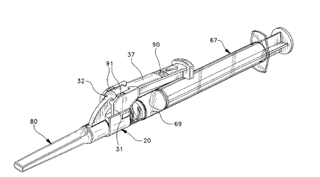
Fig. 1 is a perspective view of the needle assembly having a single-handedly
activatable needle barrier, attached to a hypodermic syringe.
Fig. 2 is an exploded perspective view of the needle assembly of Fig. 1 with
the
needle shield removed.
Fig. 3 is a top plan view of the needle shield assembly of Fig. 2 illustrating
the
burner arm in the retracted position.
CA 02210933 1997-07-21
P-3469
-4-
Fig. 4 is a top plan view of the needle assembly of Fig. 2 illustrating the
barrier
element in the extended position.
Fig. 5 is a partially cross-sectional side elevation view of the needle
assembly of
Fig. 4.
S Fig. 6 is a cross-sectional view of the needle assembly of Fig. 4 taken
along line 6-
6.
Fig. 7 is a top plan view of the barrier arm of the needle assembly of the
present
invention.
Fig. 8 is a partially cross-sectional side elevation view of the barrier arm
of Fig. 7.
Fig. 9 is a side elevational end view of the assembly of the needle cannula,
needle
hub and guide element of the present invention.
Fig. 10 is a partial cross-sectional view of the assembly of Fig. 9 taken
along line
10-10.
Fig. 11 is a top plan view of the needle shield of the present invention.
Fig. 12 is a cross-sectional view of the needle shield of Fig. 11 taken along
line 12-
12.
Fig. 13 is a partial cross-sectional side elevation view of an alternative
barner arm
of the present invention.
Fig. 14 is an alternative embodiment of the needle assembly of Figs. 1-12
wherein
the needle hub and guide element are integrally formed.
Fig. 15 is another alternate embodiment of the present invention wherein the
syringe barrel and the needle hub are integrally formed.
CA 02210933 1997-07-21
P-3469
-5-
DETAILED DESCRIPTION
While this invention is satisfied by embodiments in many different forms,
there is
shown in the drawings and will herein be described in detail preferred
embodiments of the
invention with the understanding that the present disclosure is to be
considered as
exemplary of the principles of the invention and is not intended to limit the
invention to the
embodiments illustrated. The scope of the invention will be measured by the
appended
claims and their equivalents.
Adverting to Figs. 1-12 a needle assembly 20 having a single-handedly
activated
needle barrier includes a needle cannula 21 having a proximal end 22, a distal
end 23 and a
lumen therethrough. Distal end 23 includes sharpened distal tip 25. A needle
hub 27
having an interior cavity 28, which terminates at an open proximal end 29 of
the hub, is
connected to the proximal end of needle cannula 21 so that the lumen is in
fluid
communication with the interior cavity of the hub. In this preferred
embodiment, interior
cavity 28 is frusto-conically shaped.
A guide element 31 is connected to the needle hub and includes a retaining
groove
32. In this embodiment, the guide element is attached to the needle hub
through the use of
any suitable joining technique such as adhesives, ultrasonic welding and the
like. For low
volume production attaching the guide element to an existing hub is desirable
from a cost
standpoint. It is within the purview of the present invention to include an
integrally
molded one-piece hub and guide element. For high volume production it may be
desirable
that the needle hub and guide element be of one-piece integrally molded
thermoplastic, as
illustrated in Fig. 14. The retaining groove in the guide element is generally
axially
oriented and dimensioned to accept an elongate barner arm 37, as will be
described in
CA 02210933 1997-07-21
P-3469
-6-
more detail hereinafter. The elongate barrier arm includes a proximal end 38
and a distal
end 39. The distal end of the barrier arm includes barner element 40 having a
distal end
41, a proximal end 43 and a needle passageway 44 therethrough. The elongate
barner
arm, including the barner element, is preferably integrally molded of the same
material.
S However, the barrier element and the barrier arm can be separately formed
and joined
together by any suitable means such as adhesive, ultrasonic welding and
frictional or snap-
fit type engagement. The barrier arm and barner element can also be separately
formed
and connected by a separate element such as a metal clip. The barrier arm is
positioned
within retaining groove 32 of guide element 31, and needle cannula 21 is
positioned within
needle passageway 44 of the barner element 40. The retaining groove guide
element 31 is
dimensioned and oriented to accept the elongate barrier arm.
Elongate barrier arm 37 is movable from at least a first retracted position as
illustrated in Figs. 2 and 3, wherein distal end 23 of the needle cannula
passes completely
through the barner element so that the distal end of the needle cannula is
exposed, to a
second position, as illustrated in Figs. 4 and 5, wherein the barner element
surrounds distal
end 23 and sharpened distal tip 25 of the needle cannula to prevent accidental
contact with
the distal end of the needle cannula.
The barner arm includes a finger contact surface to allow the single-handed
movement of the barner arm from the first retracted position of Figs. 2 and 3
to the
second extended position of Figs 5 and 5. In this preferred embodiment, finger
contact
surface 47 is provided on the proximal end of the elongate barrier arm. This
position for
the finger contact surface is preferred because it is the farthest position
from the sharp
needle tip. The barrier arm can be single-handedly advanced from the first
retracted
CA 02210933 1997-07-21
P-3469
_7_
position to the second extended position by holding the syringe in one hand
and pushing
on finger contact surface 47 with the thumb or the index finger of the holding
hand. The
ability to allow single-handed operation is an important feature of the
present invention
since it allows the person administering the injection to use the other hand
for other
purposes such as applying pressure to a vein to prevent bleeding.
An advantage of the present invention is that one needle assembly can be sized
so
that it can be used with several different sizes of syringes, for example
syringes having 3ml
and Sml volume capacities.
An important feature of the present invention includes locking means for
preventing movement of the barrier arm from the second extended position
wherein the
locking means is activated by movement of the burner arm into the second
extended
position. In this preferred embodiment, the burner element further includes
burner wall 49
at distal end 41 of the burner element. Barrier wall 49 includes barrier wall
aperture 50,
which is part of needle passageway 44, but having a reduced diameter which is
larger than
the needle cannula diameter and smaller than the passageway diameter thus
forming
annular ledge 51. In the preferred embodiment, locking means includes the
distal end of
the burner arm defining a distal longitudinal axis 45 and the proximal end of
the burner
arm defining a proximal longitudinal axis 46. The burner arm is configured so
that the
distal longitudinal axis and the proximal longitudinal axis are at obtuse
angle A with
respect to each other so that when the burner arm is in the second extended
position the
distal end of the needle cannula is positioned proximally of barrier wall 49
and out of
alignment with burner wall aperture 50 as best illustrated in Figs. 4 and 6.
Because distal
end 23 of the needle cannula is out of alignment with barrier wall aperture SO
any attempt
CA 02210933 1997-07-21
P-3469
_g_
to move the barner arm from the second extended position will cause the
sharpened distal
tip 25 end of the needle cannuia to embed itself into the annular ledge
portion 51 of the
barrier wall to help prevent re-exposing the distal end of the needle cannula.
This is an
important feature of the present invention because the locking means is
accomplished
without any additional parts and structures such as latches, ledges, triggers
and the like
which add to cost and complexity and can adversely affect reliability. The
simplicity of the
present invention is dramatized by the fact that a needle assembly usually
consists of two
components, a hub and a needle, while the present invention provides a
complete needle
assembly having a single-handedly activatable needle barrier with only four
components, a
needle cannula, a hub, a guide element and elongate barrier arm. If the guide
element and
needle hub are integrally molded, the present invention consists of only three
components.
Although it is not necessary to practice the present invention, it is
preferable to
have a second, redundant, component to the locking means to further resist
motion of the
barrier arm from the second extended position to the first retracted position.
This
component of the locking means is accomplished without additional components
and by
configuring the guide element and the barner arm with various combinations of
projections and recesses which will allow the barner arm to be forced through
the guide
element, in a distal direction, by application of digital pressure on finger
contacting surface
47. However, the projections and recesses are configured such that returning
the barrier
arm to the first retracted position is not possible using forces normally
associated with
operation the invention. In this embodiment, the locking means further
includes sidewalls
52 and 53 of the guide element having projections 57 and 58 respectively,
configured to
interact with a raised projection 59 on barner arm 37. Raised projection 59 is
wedge-
CA 02210933 1997-07-21
P-3469
-9-
shaped and larger at its proximal end than at its distal end. When force is
applied to the
burner arm to move the burner arm from the first retracted position to the
second
extended position, distal motion of the barrier arm will cause raised
projection 59 to
contact projections 57 and 58 on the guide element. Additional force will be
required to
force the raised projection past the guide element projections. Once this
occurs, the
projections will snap back to their original position and ledge 61 on
projection 57, and
ledge 62 on projection 58 will form a locking relationship with respect to
back wall 63 of
raised projection 59 to prevent movement, as illustrated in Fig. 4, will help
prevent
movement of the burner arm proximally from the second extended position.
In the preferred embodiment the projections 57 and 58 on the guide element and
raised projection 59 on the barrier arm are configured so that when the
barrier arm is
moved distally into the second extended position, the projections 52 and 53
will snap past
the end of raised projection 59 making an audible sound to provide an audible
indication
that the burner arm is moved into the second extended position. It is
preferred that two
projections be provided on the guide element, however, only one projection
will work and
is in the purview of the present invention.
The preferred embodiment also includes means for visually determining that the
burner arm 37 is in the second extended position which includes color segment
90 on
burner arm 37 and at least one color segment on the guide element. In this
embodiment,
there are two color segments 91 on guide element 31. When the burner arm is in
the
second extended position color segment 90 and color segments 91 will align, as
best
illustrated in Fig. 4, to form a continuous transverse color band. Any color,
including
black and white, can be used to form the color segments. However, green is
preferred
CA 02210933 1997-07-21
P-3469
- I 0-
because it is generally accepted to indicate safety. Accordingly, when the
green color
segments are precisely aligned the needle assembly of the present invention is
safely locked
with the barner arm in the second extended position.
The present invention also preferably includes structure for releasably
holding the
barrier arm in the first retracted position. This fiznction can be
accomplished by
dimensioning the barrier arm and the retaining groove in the guide element to
have a
fi-ictional fit. In this preferred embodiment, where the distal end and the
proximal end of
the barrier arm define longitudinal axes which are at an obtuse angle with
respect to each
other, the non-straight configuration of the barner an-m when it enters a
groove sized for a
straight barner anm will provide the frictional relationship to keep the
barrier arm from
moving distally under less than the desired force. Further, a recess 64 is
provided in the
barner arrn for accepting projection 58 on the guide element when the barner
arm is in the
retracted position. At this position, the barrier arm does not have to be
tightly contained
within the retaining groove. Accordingly, the plastic components are not
stressed during
the long period of time between manufacture and use. Upon applying force to
the barner
arm to move it distally, projection 58 rides up incline portion 65 of recess
64 to
immediately increase the force necessary to move the barrier arm in a distal
direction.
This structure designed to increase the force retains the barner arm in the
retracted
position. The shapes of projection 58 and incline portion 65 can also be
configured so
that there is an audible click when projection 58 leaves recess 64, further
communicating
to the healthcare worker that the barrier arm is in motion toward the second
extended
position. The barrier arm can also be releasably held in the first retracted
position by the
CA 02210933 1997-07-21
P-3469
-11-
action of a rib 34 on the barrier arm and a projection or recess in the guide
element (not
shown) which requires additional force to move rib 34 past the projection or
recess.
Although the needle assembly of the present invention is suitable for use with
a
wide variety of medical devices, including blood collection devices, it is
illustrated in Figs.
1-5 as being used with hypodermic syringe 67. Syringe 67 includes a syringe
barrel 68
having an elongate cylindrical body defining a chamber 69 for retaining fluid.
The barrel
includes an open proximal end 70, a distal end 71 and a fiusto-comically
shaped tip
extending from the distal end having a passageway therethrough in fluid
communication
with the chamber. The fiusto-comically shaped tip of the syringe barrel fi-
ictionally
engages the frusto-comically shaped cavity of the preferred needle hub 27. For
the
purpose of drawing fluid into and out of chamber 69 the syringe includes an
elongate
plunger 75 having a distal end 76 which including a stopper 77 which is in
fluid-tight
slidable engagement with the interior of the chamber.
It is within the purview of the present invention to include a needle hub
which is
integrally molded with a syringe barrel made with thermoplastic or glass
material, as
illustrated in Fig. 15. In this configuration, the tip of the syringe barrel,
which extends
from the distal end of the barrel, and the needle hub are one in the same
element. In this
configuration, the needle is preferably attached to the needle hub/syringe
barrel through
the use of an adhesive so that the needle cannot be removed from the syringe
barrel. This
configuration is ideally suited for prefilled syringes which are usually made
with a
permanently attached needle cannula.
The preferred needle assembly further includes an elongate needle shield 80
having
a distal end 81, a proximal end 82 and a cavity 83 therebetween for receiving
the needle
CA 02210933 1997-07-21
P-3469
-12-
cannula. The proximal end of the needle shield is configured to releasably
engage a portion
of the guide element for holding the needle shield in a needle protecting
position while the
barrier arm is in the ftrst retracted position. The needle shield is
configured so that when
the barrier arm is in the second extended position, the needle shield cannot
be connected
to the needle assembly. Needle shield 80 is removably attached to the guide
element
through action of projections 85 and 86 at the proximal end of the needle
shield which
interact with complimentary recesses 33 on the guide element. Needle shield 80
further
includes proximal top opening which is configured to accept the barrier arm so
that there
can be a substantially complete shielding of the needle cannula. Accordingly,
the needle
shield can effectively protect the needle cannula from damage and inadvertent
contact
from the time of manufacture until the time of use when the shield is
appropriately
discarded. After the barner element is moved to the second extended position,
the needle
shield can no longer be used with the needle assembly of the present
invention.
Adverting to Fig. 13, an alternate barner arm 137 of the present invention
includes
I S a proximal end 138, a distal end 139. The barner arm includes a barner
element 140
having a distal end 141, a proximal end 143 and a needle passageway 144
therethrough.
This alternate needle assembly functions in substantially the same manner as
the needle
assembly taught in Figs. 1-12 except that the needle passageway 144 is
generally
continuous throughout the length of the barrier element. When the barner
element is
moved to the second extended position, the sharpened tip of the needle cannula
will be
pressing firmly against the sidewalls of the needle passageway so that any
attempt to move
the elongate barrier arm 137 from the second extended position to the first
retracted
CA 02210933 1997-07-21
P-3469
-13-
position will cause the needle cannula to embed itself in the sidewall of
needle passageway
144 to inhibit proximal movement of the barner arm.
Fig. 14 illustrates an alternative embodiment of the needle shield assembly of
the
present invention, discussed in more detail herein above, wherein the needle
hub 227 and
S guide element 231 are integrally formed of one-piece construction preferably
of
thermoplastic material.
Fig. 15 illustrates still another embodiment of the present invention,
discussed
herein above, wherein needle hub 327 and syringe barrel 368 are integrally
formed into a
one-piece hub syringe barrel element 326. Needle cannula 321 is permanently
attached to
the hub syringe barrel element preferably through the use of adhesives such as
epoxy.
Guide element 321 is attached directly to the hub syringe barrel element 326
either before
or after needle cannula 321 is installed.