Note: Descriptions are shown in the official language in which they were submitted.
CA 02211180 1997-07-22
W O96/23164 PCTfUS9S/15521
EMERGENCY SAFETY LIGHT
FIELD OF THE INVENTION
The invention relates to a housing ~or an emergency light
source and, more particularly, an emergency light source for
sutomatically illuminating an area in response to a power
failure.
BACKGROUND OF THE INVENTION
Frequently, homes, offices, and industrial plant facilities
experience many types of emergency situations involving power
failures where an interior or exterior area has no light. The
power failures may be caused by electrical short circuits,
brown-outs, ~ire, accidents, natural disasters (i.e.~ floods,
hurricanes, tornadoes, etc.), or a planned shutoff of
electricity to a facility or dwelling. As a result of these
,emergencies, most facilities, and especially residential homes,
do not have emergency generators to provide lighting, or they
only have emergency lighting in the form of portable light
sources, such as ~lashlights.
A need exists for a simple and easily installable emergency
light source which includes a fixedly-attached housing for
replacement of standard switch plates and which activates itself
in response to a power failure of any kind.
DESCRIPTION OF THE PRIOR ART
Switch plate devices having an illumination source and/or
having a rechargeable flashlight contained thereon are
commercially available and have been disclosed in the prior art.
For example, U.S. Patent No. 4,514,789 discloses a housing on a
switch plate having an LED to locate a light switch in the dark.
U.S. Patent No. 4,611,264 discloses a housing adhesively
attached to a switch plate having a light to locate the light
switch in the dark. The housing can be removed and used as a
flashlight.
CA 02211180 1997-07-22
W O 96/23164 PCTrUS95/15521
The prior art devices do not disclose a housing whic~l is
easily installable and connectable to a conventional light
switch to provide automatic illumination to an area when a power
failure occurs.
Accordingly, it is a primary object of the present
invention to provide a simple and easily installable emergency
light source which includes a housing for the replacement of
standard switch plates and which activates itself in response to
a power failure of any kind.
Another object of the present invention is to provide a
housing for an emergency light source which is electrically
connectable to a conventional light switch.
Another object of the present invention is to provide an
emergency light source which is battery operated and can operate
with different types of light sources, such as a fluorescent
lamp or an incandescent lamp.
A further object of the present invention is to provide an
emergency light source which has a sensing device for sensing a
power failure and automatically actuating the emergency light
source.
A still further object of the present invention i6 to
provide a housing for an emergency light source which can be
mass produced in an automated and economical manner and is
relatively inexpensive.
SUMMARY OF THE INVENTION
The present invention provides a housing for an emergency
light source which is electrically connectable to a conventional
light switch. The housing replaces a conventional switch plate
and has at least one opening for receiving the switch actuator
of the light fiwitch. The housing may have several switch
openings for a plurality of switch actuators. The housing
includes wires for electrical connection to the light switch.
The housing is divided into upper and lower sections,
wherein the upper section includes a battery compartment, a
CA 02211180 1997-07-22
W O96/23164 PCT~US95/15521
printed circuit board compartment, and an opening to receive the
switch actuator. The lower housing section includes a compact
fluorescent lamp having reflectors and a diffuser cover.
The fluorescent lamp is connected to the batteries via the
printed circuit board. The printed circuit board includes a
recharger for the batteries; a power-sensing device for sensing
power interruption; an ON/OFF relay switch which is turned on in
response to a power failure; a LED charging indicator light to
show that the batteries are charging; a manual test switch; and
a transformer, fluorescent ballast, and starter components for
the fluorescent lamp. The printed circuit board is electrically
connected to the light switch.
Alternatively, the power source may be located outside of
the housing at a remote location, and the light source may be
one or more incandescent lamps.
BRIEF DESCRIPTION OF THE DRAWINGS
Further ob~ects, features, and advantages of the present
inventio~ will become apparent upon consideration of the
detailed description of the presently-preferred embodiments,
when taken in conjunction with the accompanying drawings,
wherein:
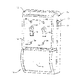
Figure 1 is a perspective vlew of the present invention
showing the emergency safety light having two switch actuators,
a switch cover, and a light diffuser cover;
Figure 2 is a front plan view of the present invention with
the cover removed, showing the upper and lower sections of the
housing having the batteries, the printed circuit board, and the
compact fluorescent lamp;
Figure 3 is a circuit diagram for the emergency light
showins the circuit wiring for the batteries, printed circuit
board, and the compact fluorescent lamp; and
Figure 4 is a breakaway perspective view of the present
invention showing the upper and lower sections of the housing
which depicts the battery compartment, the batteries, the light
CA 02211180 1997-07-22
W O96/23164 PCTrUS9S/lSS21
switch opening, the printed circuit board compartment, the P.C.
board, the fluorescent lamp compartment, the fluorescent lamp,
the mylar reflector, and the plastic reflector.
DETAILED DESCRIPTION OF
THE PREFERRED EMBODIMENT
The preferred embodiment of the present invention provldes
for an emergency safety light housing 10 having front and rear
housing sections 12 and 20, as shown in Figure 1 of the
drawings. The front housing section 12 comprises an upper
plastic switch plate cover 14 having at least one light switch
opening 16 and a lower clear acrylic diffuser cover 18. Switch
plate cover 14, in other embodiments, may have a plurality of
switch openings 16 to accommodate the light switch actuators 60.
Switch actuators 60 may be of any type, such as the one shown,
lS or a rocker-arm type. Switch plate cover 14 may also have a
plurality of mounting openings 48 for mounting screws 36, as
depicted in Figures 1 and 4. Switch plate cover 14 may be of
plastic, metal, wood, ceramic, or other suitable materials of
varying colors and designs. The housing 10, in alternate
embodiments, may have shapes that are spherical, oval,
cylindrical, or other suitable geometrical designs.
The rear housing section 20, as depicted in Figures 2 and
4, comprises an upper section 22 and a lower section 24. The
upper housing section 22 includes an opening 26 for receiving
the light switch assembly 28, a battery compartment 30, a
printed circuit board compartment 32, and a plurality of
mounting receptacle holders 34 for receiving mounting screws 36
for cover plate 14.
The lower housing section 24 includes a metallized mylar
reflective film 38 permanently affixed to the rear wall 40 of
housing section 20; a metallized plastic reflector 42 having a
concave shape and an opening 43 aligned with reflective film 38;
and a compartment 44 for receiving a light source 46. L~ght
source 46 can be a fluorescent lamp fixture of 5, 7, or 9 watts
CA 02211180 1997-07-22
W O96123164 PCTAUS9S/ISS21
of power, or it can be one or more incandescent lamps having 15
or 25 watts of power. Of course, other wattages may be used,
and other types of light sources may be used, where appropriate.
Light source 46 is hard wired at 84 to the circuit board 62.
The electrical arrangement of the present invention, as
shown in Figures 3 and 4, includes circuit wires 64 and 66
connected to circuit board 62 for connection to light switch
assembly 28 after the conventional switch plate has been
removed. Circuit board 62 also includes components for a
battery recharger 68 for charging batteries 50; a charging
indicator light 70, such as an LED, that remains ON to indicate
that the batteries are recharging; a manual test switch 72 for
testing the functioning of light source 46; a power interruption
detector 74 for sensing a power failure; an ON/OFF relay switch
76 which is turned ON in a response to a power failure; and a
transformer 78, a fluorescent ballast 80, and a starter 82 for
fluorescent light source 46. The printed circuit board 62 has
openings 88 for holding braces 86 located on wall 40, which
holds the circuit board 62 firmly in place when emergency light
housing 10 is on a wall in a dwelling or other building.
The power source 50 can be a battery or plurality of
batteries for energizing the light source 46 when a power
failure occurs. In this preferred embodiment, as shown in
Figures 2, 3, and 4, the power source 50 is a series of four AA
batteries. The batteries 50 are placed in the battery
compartment 30 between receptor plates 56, 58 and are
electrically connected via circuit wires 52, 54 to the printed
circuit board 62. In an alternate embodiment, the power source
46 may be located outside of the housing 10 at a remote location
in the form of solar energy cells, a hydrological energy source,
12-volt batteries, or other appropriate power sources, which can
energize the light source 46 when a power failure occurs.
I
CA 02211180 1997-07-22
W O96/23164 PCTrUS95/lSS21
OPERATION AND INSTALLATION
OF THE PRESENT INVENTION
When a power failure occurs, the power interruption
detector 74 senses this loss of power and causes the ON~OFF
relay switch 76 to move to the ON position. This allows energy
to be supplied from the power source 50 to the light source 46,
which instantly illuminates the unlighted area. The mylar
reflective film 38 and metallzied plastic reflector 42 enhance
the amount and area of illumination.
Prior to a power failure, operation of the LED charging
indicator light 70 shows that the power source of batteries 50
is charging, and a manual test of switch 72 tests the
functioning of the light source 46 to see if illumination
occurs.
To install the housing 10 of the present invention, it is
only necessary to remove the conventional switch plate and then
connect switch circuit wires 64 and 66 of the printed circuit
board 62 in the upper housing section 22 to the light switch 28.
The emergency light source 46 is not energized by this
connection until there is a power failure, or until there is a
manual testing of test switch 72, which illuminates the light
source 46.
ADVANTAGES OF THE PRESENT INVENTION
Accordingly, a primary advantage of the present invention
is that it provides a simple and easily installable emergency
light source which includes a fixedly-attached housing for the
replacement of standard switch plates and which activates itself
in response to a power failure of any kind.
Another advantage of the present invention is that it
provides a housing for an emergency light source which is
electrically connectable to a conventional light switch.
CA 02211180 1997-07-22
W O96/23164 . PCTrUS9~115521
Another advantage of the present invention is that it
provides an emergency light source which is battery operated and
can operate with different types of light sources, such as a
fluorescent lamp or an incandescent lamp.
A further advantage of the present invention is that it
provides an emergency light source which has a sensing device
for sensing a power failure and automatically actuating the
emergency light source.
A still further advantage of the present invention is that
it provides a housing for an emergency light source which can be
mass produced in an automated and economical manner and is
relatively inexpensive.
A latitude of modif ication, change, and substitution is
intended in the foregoing disclosure, and in some instances,
some features of the invention will be employed without a
corresponding use of other features. Accordingly, it is
appropriate that the appended claims be construed broadly and in
a manner consistent with the spirit and scope of the invention
herein.