Language selection

Search

Patent 2211202 Summary

Third-party information liability

Some of the information on this Web page has been provided by external sources. The Government of Canada is not responsible for the accuracy, reliability or currency of the information supplied by external sources. Users wishing to rely upon this information should consult directly with the source of the information. Content provided by external sources is not subject to official languages, privacy and accessibility requirements.

Claims and Abstract availability

Any discrepancies in the text and image of the Claims and Abstract are due to differing posting times. Text of the Claims and Abstract are posted:

  • At the time the application is open to public inspection;
  • At the time of issue of the patent (grant).
(12) Patent Application: (11) CA 2211202
(54) English Title: BALL CLAMP BOLT
(54) French Title: BOULON DE SERRAGE A BILLES
Status: Deemed Abandoned and Beyond the Period of Reinstatement - Pending Response to Notice of Disregarded Communication
Bibliographic Data
(51) International Patent Classification (IPC):
  • F16B 5/06 (2006.01)
  • F16B 13/10 (2006.01)
  • F16B 21/16 (2006.01)
(72) Inventors :
  • HALDER, WERNER (Germany)
  • HUMMEL, DIETER (Germany)
(73) Owners :
  • ERWIN HALDER KG
(71) Applicants :
  • ERWIN HALDER KG (Germany)
(74) Agent: KIRBY EADES GALE BAKER
(74) Associate agent:
(45) Issued:
(22) Filed Date: 1997-07-21
(41) Open to Public Inspection: 1998-04-23
Availability of licence: N/A
Dedicated to the Public: N/A
(25) Language of filing: English

Patent Cooperation Treaty (PCT): No

(30) Application Priority Data:
Application No. Country/Territory Date
196 43 708.3-12 (Germany) 1996-10-23

Abstracts

English Abstract


Abstract
The invention refers to a ball clamp bolt used to provide
a detachable connection between two plates each of which has a
hole. The ball clamp bolt has a grip, a positioning bolt
which can be shifted relatively to the grip against the force
of a first spring, this positioning bolt having a locking
piece at its free end. The locking piece can be adjusted by
means of a plunger which can be shifted relatively to the
positioning bolt from a locking position preventing the
passage of the positioning bolt through the holes to a release
position extending into a recess in the plunger and permitting
such passage. Between the plunger and the positioning bolt
there is a second spring. The recess has on the side facing
the locking piece a sidewall inclined to the axis of the
plunger on which the locking piece can slide into the recess.


French Abstract

Cette invention concerne un boulon de serrage à billes servant à établir une connexion détachable entre deux plaques percées toutes deux d'un trou. Ce boulon de serrage à billes comporte une poignée et un boulon de positionnement susceptible de se déplacer par rapport à la poignée en agissant contre un premier ressort, ce boulon de positionnement étant muni d'une pièce de verrouillage sur son extrémité libre. On peut ajuster la pièce de verrouillage au moyen d'un manche mobile pouvant être déplacé par rapport au boulon de positionnement en le faisant passer d'une position de verrouillage, où le boulon de positionnement n'est pas en mesure de traverser les trous, à une position de desserrage où, en se retirant dans un enfoncement du manche, cette pièce laisse alors au boulon de positionnement la liberté de les traverser. Un deuxième ressort est placé entre le manche et le boulon de positionnement. Du côté de la pièce de verrouillage, le renfoncement présente une paroi latérale orientée suivant l'axe du manche, sur lequel la pièce de verrouillage peut glisser pour entrer dans le renfoncement.

Claims

Note: Claims are shown in the official language in which they were submitted.

- 5 -
Claims:
1. A ball clamp bolt providing a detachable connection
between two pieces, especially two plates, each having a hole,
with a grip, a positioning bolt which can be pushed through
the holes and can be shifted relatively to the grip against
the force of a first spring, the positioning bolt having at
its free end a locking piece, adjustable by means of a plunge,
which can be shifted relatively to the positioning bolt, from
a locking position preventing the passage of the positioning
bolt through the holes to a release position extending into a
recess of the plunger and permitting such passage,
characterized in that between the plunger and the positioning
bolt there is a second spring and that the recess has on the
side facing the locking piece a sidewall inclined to the axis
of the plunger on which sidewall the locking piece can slide
into the recess.
2. A ball clamp bolt as in Claim 1, characterized in that
the plunger engages on the side facing away from the locking
piece in a plunger cap, that the plunger cap has a face for
making contact with the positioning bolt and that in the
locking position the gap between the face and the positioning
bolt equals the gap between the locking piece and the inclined
sidewall.
3. A ball clamp bolt as in Claim 2, characterized in that
the plunger has a plunger head located in a pocket of the
plunger cap, and that there is a collar at a distance from the
plunger head in the pocket.
4. A ball clamp bolt as in Claim 3, characterized in that
the second spring is located between the plunger head and the
positioning bolt.
5. A ball clamp bolt as in Claim 1, Claim 2, Claim 3 or
Claim 4, characterized in that the inclined sidewall has a

- 6 -
rounded shape.
6. A ball clamp bolt as in Claim 1, Claim 2, Claim 3, Claim
4 or Claim 5, characterized in that two of the locking pieces
are provided.
7. A ball clamp bolt as in Claim 1, Claim 2, Claim 3, Claim
4, Claim 5 or Claim 6, characterized in that the locking piece
is ball-shaped.

Description

Note: Descriptions are shown in the official language in which they were submitted.


CA 022ll202 l997-07-2l
BALL CL~IMP BOLT
This invention relates to a ball clamp bolt providing a
detachable connection between two pieces, especially two
plates, each of which has a hole. The bolt is provided with a
grip, a positioning bolt which can be pushed through the holes
and can be shifted relatively to the grip against the force of
a first spring, the positioning bolt having at its free end a
locking piece, adjustable by means of a plunge, which can be
shifted relatively to the positioning bolt, from a locking
o position preventing the passage of the positioning bolt
through the holes to a release position extending into a
recess of the plunger and permitting such passage.
sall clamp bolts of this kind are known from industrial
practice. When not in use, they are in the locking position.
When two plates are to be joined together, the plunger is
first adjusted relatively to the positioning bolt to the point
where it will permit the locking piece to enter the recess so
that the locking piece is now in the release position. The
positioning bolt is then shifted further relatively to the
grip and pushed through the holes in the plates. The plates
will, however, only be firmly joined together if, after the
plunger has been released, the locking piece is transferred
from the release position back to the locking position. Until
this happens the ball clamp bolt cannot exert any clamping
force along the axis so that at this stage in the creation of
the connection, the ball clamp bolt merely acts as a ball
locking bolt.
The object of the invention is therefore to provide a
ball clamp bolt of the kind referred to above in such a way
that the plates will be clamped against each other as soon as
the positioning bolt has been pushed through the holes.
This object is accomplished in accordance with the
invention by locating a second spring between the plunger and
the positioning bolt and providing in the recess on the side
facing the locking piece a sidewall inclined to the axis of
the plunger on which the locking piece can slide into the
recess.
The ball clamp bolt in accordance with the invention

CA 02211202 1997-07-21
offers the advantage that the plunger can be adjusted to the
point where the locking piece is beside the recess and stays
there in the locking position. Only when one plate or both
plates are pushed on to the positioning bolt and the
positioning bolt is pushed through the holes is the locking
piece on the inclined sidewall pressed into the recess, the
second spring being then under tension, so that as soon as the
plates have passed the locking piece the spring can withdraw
the plunger and press the locking piece out of the recess, the
consequence being that the locking piece is in the release
position only during the brief period in which the positioning
bolt is being pushed through and that as soon as the
positioning bolt has been pushed through the holes in the
plates the latter are subject to initial tension.
As it is difficult to position the plunger in such a way
that the locking piece will be immediately beside the inclined
sidewall in the recess an especially preferred embodiment of
the invention provides for the plunger to engage on the side
facing away from the locking piece in a plunger cap, for the
plunger cap to have a face for making contact with the
positioning bolt and, in the locking position, for the gap
between the face and the positioning bolt to equal the gap
between the locking piece and the inclined sidewall. The
result is that when the plunger is first actuated, the locking
piece is transferred from a locking position in which it is
secured and cannot slide into the recess into a locking
position from which it can be adjusted into the release
position. This clearly simplifies the operation of the ball
clamp bolt because the positioning of the locking piece
immediately beside the recess no longer depends on the
dexterity of the operator.
It is also provided that the plunger has a plunger head
located in a pocket in the plunger cap and that there is a
collar at a distance from the plunger head in the pocket. The
effect of this is that when the locking piece is transferred
to the release position with the plunger head already in
contact with the positioning bolt the plunger head can only be

CA 02211202 1997-07-21
shifted over a predetermined distance relatively to the
plunger cap so that the locking piece in the recess cannot be
pushed too far along the axis and can immediately after the
passage of the positioning bolt through the holes in the
plates be quickly transferred back to the locking position.
It has in this connection been found advantageous to place the
second spring between the plunger head and the positioning
bolt.
Similarly, it is advantageous for the inclined sidewall
o to have a rounded shape, for then the beginning and the end of
the inclined sidewall are relatively steep, so that relatively
greater force is required to begin the movement from the
locking position to the release position, which prevents an
unintended adjustment.
In order to prevent the positioning bolt from tilting in
the holes in the plates two of the locking pieces provided are
ball-shaped.
The invention is explained in detail below with reference
to a preferred embodiment illustrated in the accompanying
drawing. In the drawing:-
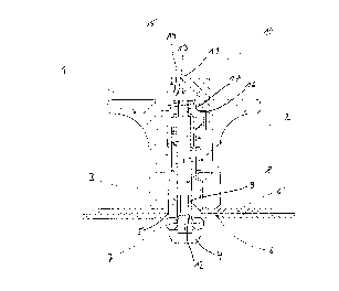
Fig. 1 shows a longitudinal section through a preferredball clamp bolt in accordance with the invention which is
being used to join two plates together.
The ball clamp bolt shown in the drawing has a grip 1 and
a positioning bolt 3 which can be shifted relatively to the
grip 1 along the axis of the latter against the force of a
first spring 2. At the free end 4 of the positioning bolt 3,
which can be pushed through the holes 5 in two plates 6, 6' to
join them together, two ball-shaped locking pieces 7 are
located. A plunger 8 is positioned in a central hole in the
positioning bolt 3, which plunger can be shifted relatively to
the bolt and which has a recess 9 on the side facing the free
end 4 of the positioning bolt 3. The plunger 8 can be
adjusted in the central hole in such a way that the locking
pieces 7 can be transferred from a locking position
illustrated in the drawing in which the locking pieces 7 are
in contact with the outer circumference of the plunger 8, to a

CA 022ll202 l997-07-2l
release position in which the locking pieces 7 are in the
recess.
Between the plunger 8 and the positioning bolt 3, a
second spring 10 is located. The recess 9 has on the side
facing the locking piece 7 a sidewall 12 inclined to the axis
11 of the plunger 8 so that when the positioning bolt 3 is
pushed through the holes 5 in the plates 6, 6' the locking
pieces 7 are pushed into the recess 9 from the edges of the
holes 5; the locking pieces 7 pull the plunger 8 against the
o force of the second spring 10 further towards the free end 4
of the positioning bolt 3. After the locking pieces 7 have
passed through the holes 5, the plunger 8 is shifted by the
force of the second spring 10 back to its initial position and
the locking pieces 7 on the inclined sidewall 12 are pressed
back out of the recess 9.
The plunger 8 has a plunger head 13 located in a pocket
14 of a plunger cap 15, this cap having on the side facing the
positioning bolt 3 a face with which it makes contact with the
positioning bolt 3 when the plunger is shifted, so that when
further force is exerted, the positioning bolt 3 is shifted
along the axis. When the locking pieces 7 are in the locking
position, the gap between the face 16 of the plunger cap 15
and the positioning bolt 3 equals the gap between the locking
piece 7 and the inclined sidewall 12, so that when the plunger
8 is actuated, the locking pieces 7 are positioned on the edge
of the recess 9 at the beginning of the inclined sidewall 12.
There is a collar 17 at a distance from the plunger head 13
located in the pocket 14 of the plunger cap 15, which collar
serves to limit the movement of the plunger 8 relatively to
the plunger cap 15 and consequently to the positioning bolt 3.
In the embodiment shown in the drawing, the second spring
10 is located between the plunger head 13 and the positioning
bolt 3 and the inclined sidewall has a rounded shape.

Representative Drawing
A single figure which represents the drawing illustrating the invention.
Administrative Status

2024-08-01:As part of the Next Generation Patents (NGP) transition, the Canadian Patents Database (CPD) now contains a more detailed Event History, which replicates the Event Log of our new back-office solution.

Please note that "Inactive:" events refers to events no longer in use in our new back-office solution.

For a clearer understanding of the status of the application/patent presented on this page, the site Disclaimer , as well as the definitions for Patent , Event History , Maintenance Fee  and Payment History  should be consulted.

Event History

Description Date
Inactive: IPC from MCD 2006-03-12
Time Limit for Reversal Expired 2003-07-21
Application Not Reinstated by Deadline 2003-07-21
Inactive: Abandon-RFE+Late fee unpaid-Correspondence sent 2002-07-22
Deemed Abandoned - Failure to Respond to Maintenance Fee Notice 2002-07-22
Application Published (Open to Public Inspection) 1998-04-23
Inactive: IPC assigned 1997-10-21
Classification Modified 1997-10-21
Inactive: IPC assigned 1997-10-21
Inactive: First IPC assigned 1997-10-21
Application Received - Regular National 1997-10-01
Filing Requirements Determined Compliant 1997-10-01
Letter Sent 1997-10-01
Inactive: Filing certificate - No RFE (English) 1997-10-01

Abandonment History

Abandonment Date Reason Reinstatement Date
2002-07-22

Maintenance Fee

The last payment was received on 2001-06-13

Note : If the full payment has not been received on or before the date indicated, a further fee may be required which may be one of the following

  • the reinstatement fee;
  • the late payment fee; or
  • additional fee to reverse deemed expiry.

Please refer to the CIPO Patent Fees web page to see all current fee amounts.

Fee History

Fee Type Anniversary Year Due Date Paid Date
Application fee - standard 1997-07-21
Registration of a document 1997-07-21
MF (application, 2nd anniv.) - standard 02 1999-07-21 1999-04-22
MF (application, 3rd anniv.) - standard 03 2000-07-21 2000-05-08
MF (application, 4th anniv.) - standard 04 2001-07-23 2001-06-13
Owners on Record

Note: Records showing the ownership history in alphabetical order.

Current Owners on Record
ERWIN HALDER KG
Past Owners on Record
DIETER HUMMEL
WERNER HALDER
Past Owners that do not appear in the "Owners on Record" listing will appear in other documentation within the application.
Documents

To view selected files, please enter reCAPTCHA code :


To view images, click a link in the Document Description column. To download the documents, select one or more checkboxes in the first column and then click the "Download Selected in PDF format (Zip Archive)" or the "Download Selected as Single PDF" button.

List of published and non-published patent-specific documents on the CPD .

If you have any difficulty accessing content, you can call the Client Service Centre at 1-866-997-1936 or send them an e-mail at CIPO Client Service Centre.


Document
Description 
Date
(yyyy-mm-dd) 
Number of pages   Size of Image (KB) 
Representative drawing 1998-05-11 1 8
Description 1997-07-21 4 203
Claims 1997-07-21 2 51
Abstract 1997-07-21 1 22
Drawings 1997-07-21 1 18
Cover Page 1998-05-11 2 63
Courtesy - Certificate of registration (related document(s)) 1997-10-01 1 118
Filing Certificate (English) 1997-10-01 1 165
Reminder of maintenance fee due 1999-03-23 1 111
Reminder - Request for Examination 2002-03-25 1 119
Courtesy - Abandonment Letter (Request for Examination) 2002-09-30 1 170
Courtesy - Abandonment Letter (Maintenance Fee) 2002-08-19 1 182