Note: Descriptions are shown in the official language in which they were submitted.
CA 022112~0 1997-07-23
~fl
- 1 - CFO 12185 ~5
Developing Device
BACKGROUND OF THE INVENTION
Field of the Invention
The present invention relates to a developing
device used in an image forming apparatus of the
electrophotographic or electrostatic recording scheme
to develop an electrostatic image on an image holding
member.
Related Background Art
In an image forming apparatus of the
electrophotographic scheme, an electrostatic image
formed on the photosensitive member is developed with a
toner in the developing device.
In such a developing device, a developer is held
by the developing sleeve placed to oppose the
photosensitive member so as to perform developing. So,
toner must be prevented from leaking out via the end
portions of the developing sleeve.
To do this, seal members are provided for the
developing sleeve end portions. As such a seal member
for preventing leakage of toner, an elastic member such
as a felt or foam rubber member has widely been used.
Figs. 9 and 10 show a typical example of this member.
Fig. 9 is a sectional front view showing the main part
of a developing device. Fig. 10 is a sectional side
view showing the main part of the developing device.
CA 022ll2~0 l997-07-23
-- 2 --
As shown in Fig. 9, a developing sleeve 5
incorporates a magnetic roller 6. The developing
sleeve 5 is rotatably supported on a developer
container 3 through a sleeve bearing 12, as shown in
Fig. 10. With this arrangement, toner supplied from
the developer container 3 adheres to the surface of the
developing sleeve 5 owing to the magnetic force of the
magnetic roller 6, and is regulated by a developing
blade 7 to a predetermined thickness. Then, with
rotation of the developing sleeve 5, the toner adheres
to a latent image on the photosensitive drum 1 at a
position opposing thereto, thus developing the image.
Elastic seal members 8 are mounted on the two
longitudinal end portions of the developing sleeve 5
outside the developing area. More specifically, the
elastic seal members 8 are mounted on the front portion
(on the opening side) of the developing sleeve 5, which
is mounted on the developer container 3, and the rear
portion (on the opposite side to the opening side) of
the developing sleeve 5. These elastic seal members 8
are pressed against the outer surface of the developing
sleeve 5 to prevent leakage of the toner.
In this sealing method of pressing the elastic
members against the developing sleeve, the torque
required to drive the developing sleeve in a developing
operation becomes large.
CA 022112~0 1997-07-23
In addition, as the number of times the elastic
seal members are used increases, the sealing ability of
each seal member deteriorates.
The sealing method of pressing the elastic members
against the developing sleeve is not suitable for a
developing device to realize higher operation speed and
longer service life.
Under the circumstances, a technique of forming
magnetic seals has been proposed. According to this
technique, magnets are arranged at the two ends of a
developing sleeve through a gap, and magnetic seals are
formed by the magnetic fields generated by the magnets
outside the developing sleeve and the magnet inside the
developing sleeve.
Fig. 11 is a sectional front view showing an
example of a developing device using magnetic seal
members. Referring to Fig. 11, magnetic seal members
20 made of magnets are wound around the two end
portions of a developing sleeve 5 to oppose its outer
surface through a predetermined gap g. In this state,
the magnetic seal members 20 are mounted on a developer
container 3, together with the developing sleeve 5.
Each magnetic seal member 20 is magnetized to a
magnetic pole pattern like the one shown in Fig. 12.
The gap g between the outer surface of the developing
sleeve 5 and the surface of each magnetic seal member
20 is filled with a magnetic brush due to a
CA 022112~0 1997-07-23
triboelectric brush of the toner formed along magnetic
lines of force 24, thereby preventing the toner from
leaking out of the developing area.
As a magnetic seal member, a member having the
magnetization pattern shown in Fig. 13 or 14 may be
used.
With the use of this technical means, since the
developing sleeve 5 and the magnetic seal members 20
can be arranged in a non-contact state, the rotational
torque of the developing sleeve 5 is considerably
small. For this reason, a compact, inexpensive driving
motor can be used. In addition, since variations in
rotational torque are small, the developing sleeve 5
and the photosensitive drum l do not easily undergo
rotation variations. This technique is therefore
suitably used to increase the operation speed of the
devlce .
Furthermore, since the magnetic seal members 20
are free from wear and the like, they can be used
semipermanently and recycled.
In this magnetic sealing method, the sealing
performance is influenced by the magnetic flux density.
Although a sealing effect can be enhanced by using
magnets having strong magnetic forces, the device
increases in size, and the magnetic forces may inflict
adverse effects on the developing area.
CA 022112~0 1997-07-23
SUMMARY OF THE INVENTION
It is an object of the present invention to
provide a developing device which attains a reduction
in driving torque for a developer holding member.
It is another object of the present invention to
provide a developing device which can obtain a high
magnetic sealing performance.
It is still another object of the present
invention to provide a developing device comprising:
a developer container containing magnetic
particles;
a developer holding member formed at an opening
portion of the developer container, the developer
holding member rotating while holding a developer;
a magnetic field generating member placed in the
developer holding member;
a magnet placed along a circumferential direction
of the developer holding member to form a magnetic seal
in cooperation with the magnetic field generating
member; and
a magnetic member placed to be adjacent to the
magnet.
The above and other objects, features, and
advantages of the present invention will be apparent
from the following detailed description in conjunction
with the accompanying drawings and the appended claims.
CA 022112~0 1997-07-23
BRIEF DESCRIPTION OF THE DRAWINGS
Fig. 1 is a sectional view showing a process
cartridge having a developing device according to an
embodiment of the present invention:
Fig. 2 is a partial perspective view of the
developing device;
Fig. 3A is a sectional view taken along a line
3A - 3A in Fig. 2, and Fig. 3B is an enlarged view of a
portion in Fig. 3A;
Fig. 4 is a partial perspective view of a
developing device according to another embodiment of
the present invention;
Fig. 5A is a sectional view taken along a line
5A - 5A in Fig. 4, and Fig. 5B is an enlarged view of a
portion in Fig. 5A;
Fig. 6 is a sectional view taken along a line 5A -
5A in Fig. 4;
Fig. 7 is a sectional view taken along a line 7 -
7 in Fig. 6;
Fig. 8 is a sectional view taken along a line 8 -
8 in Fig. 6;
Fig. 9 is a sectional front view of the developing
device portion of a conventional process cartridge;
Fig. 10 is a sectional view showing the main part
of the conventional developing device;
Fig. 11 is a sectional view showing a developing
device using a magnetic seal;
CA 022112~0 1997-07-23
Figs. 12, 13 and 14 are perspective views showing
the magnetization patterns of a magnetic seal member;
Fig. 15 is a view showing the magnetic lines of
force along a cross-section taken along a line 15 - 15
in Fig. 12; and
Fig. 16 is a view showing part of the developing
device using magnetic seal members.
DETAILED DESCRIPTION OF THE PREFERRED EMBODIMENTS
The embodiments of the present invention will be
described below with reference to the accompanying
drawings.
<First Embodiment>
Fig. 1 is a sectional view showing a process
cartridge which uses a developing device of an
embodiment of the present invention and is detachably
mounted in an image forming apparatus body.
This process cartridge is a unit including at
least a photosensitive member as an image holding
member for holding an electrostatic image and a
developing device for developing the electrostatic
image on the photosensitive member.
As shown in Fig. 1, in the process cartridge
according to the configuration of this embodiment, a
developing means 4 including a charging means 2, a
developer container 3, a developing sleeve 5 as a
developer holding member, and a developing blade 7, and
CA 022112~0 1997-07-23
a cleaning means 11 are arranged around a
photosensitive drum 1. These components are covered
with a housing constituted by frames 15, 16, 17, and
18, and integrated into a cartridge. This cartridge is
detachably mounted in an image forming apparatus body
(not shown).
The developing sleeve 5 incorporates a magnetic
roller 6, and is rotatably mounted on the developer
container 3 through a sleeve bearing (not shown).
Monocomponent magnetic toner as a developer supplied
from the developer container 3 adheres to the surface
of the developing sleeve 5 owing to the magnetic force
of the magnetic roller 6, and is regulated by the
developing blade 7 to a predetermined thickness. The
resultant toner is brought to a position where it
opposes a latent image on the photosensitive drum 1
upon pivotal movement of the developing sleeve 5. At
this position, the toner adheres to the latent image to
develop it.
The developing means 4 has magnetic seal members
21 arranged along the outer surfaces of the two end
portions of the developing sleeve 5. Each magnetic
seal member 21 is mounted on the developer container 3
with a gap g being ensured between the magnetic seal
member 21 and the outer surface of the developing
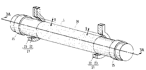
sleeve 5. As shown in Fig. 2, the magnetic seal member
21 is formed by joining a magnetic plate (magnetic
CA 022112~0 1997-07-23
member) 23 to a side surface of a magnet 22 in its
widthwise direction which coincides with the
longitudinal direction of the developing sleeve 5.
Each magnetic seal member 21 in this embodiment
will be described in detail next.
The magnetic seal member 21 is constituted by the
following two constituent elements: the magnet 22 which
is an injection molded member which is 3 mm wide and
made of a nylon binder containing an Nd-Fe-B magnetic
powder; and the magnetic plate 23 which is a l-mm thick
iron member.
As shown in Figs. 12, 13, and 14, the magnet 22 is
magnetized in a plurality of sections along the
circumferential direction of the developing sleeve. It
is preferable that the magnet 22 be alternately
magnetized to south and north poles, as in the magnetic
seal member 20 shown in Fig. 12. Alternatively, the
magnet 22 may be magnetized so as to have opposite
polarities in the side surfaces thereof, as in the
magnetic seal member 20 shown in Fig. 14.
Alternatively, as in the magnetic seal member 20 shown
in Fig. 14, the magnet 22 may be magnetized so as to
have opposite polarities on the front side which
opposes the developing sleeve 5, and the rear side.
The magnetic plate 23 is preferably made of a soft
magnetic material, such as soft iron, silicon steel, or
CA 022112~0 1997-07-23
-- 10 --
Permalloy, which has high magnetic susceptibility and
small magnetic hysteresis loss.
As a method of joining the magnet 22 and the
magnetic plate 23, insert molding of injection molding
is used. Even if, however, these members are joined to
each other by a double-coated adhesive tape or an
adsorbing manner using only a magnetic force, the same
effects to be described later can be obtained. The gap
between the developing sleeve 5 and the magnetic seal
member 21 is 0.1 to 0.7 mm, and the magnetic flux
density on the surface of the developing sleeve 5,
caused by the magnetic force of the magnetic seal
member 21 is about 1,000 to 2,000 Gs. The magnets 22
and the magnetic plates 23 of the magnetic seal members
21 are positioned such that the magnets 22 are located
on the near sides of an opening portion 26 (the middle
portion of the developing sleeve 5 which is indicated
by the dots in Fig. 2) of the developer container 3,
and the magnetic plates 23 are located on the far sides
of the opening portion 26 (the two longitudinal end
portions of the developing sleeve 5 in Fig. 2).
As described above, since the magnet 22 is located
on the near side of the opening portion 26 of the
developer container 3, and the magnetic plate 23 is
located on the far side of the opening portion 26,
magnetic lines of force 24 which run from the front
side to the rear side of the magnetic seal member 21
CA 022112~0 1997-07-23
are formed between the magnet 22 and the magnetic plate
23 to enter the magnetic plate 23 with high
permeability, as indicated by Fig. 3B which is an
enlarged view of a portion A in Fig. 3A. Unlike the
prior art shown in Figs. 15 and 16, almost no magnetic
lines of force run beyond the width of the magnetic
seal member 21.
Since the toner spreading along the magnetic lines
of force 24 on the surface of each magnetic seal member
21 is not present outside the magnetic plate 23 on the
magnetic plate 23 side (outside the opening portion
26), the toner does not come into contact with a spacer
roller 25 upon rotation of the developing sleeve 5.
For this reason, each spacer roller 25 can be placed
near the side surface of the magnetic seal member 21.
Apparently, therefore, the process cartridge can be
reduced in size, and at the same time, the image
forming apparatus body itself can be reduced in size.
In addition, since the toner on each magnetic seal
member 21 does not spread outside the opening portion
26 of the developer container 3 by the magnetic plate
23, the toner can be reliably held within the range in
which the magnetic force on the surface of the magnetic
seal member 21 is strong. Even if a shock or the like
acts on the process cartridge when the user
attaches/detaches it to/from the image forming
CA 022ll2~0 l997-07-23
- 12 -
apparatus, no toner leaks. That is, good sealing
characteristics can be obtained.
Furthermore, since the magnetic plate 23 is joined
to the side surface of each magnet 22, the magnetic
lines of force 24 enter the magnetic plate 23, as
described above. That is, the diverging magnetic lines
of force are converged onto the magnetic plate 23. As
a result, the magnetic flux density on the surface of
the magnet 22 increases to attain a further improvement
in sealing characteristics. Moreover, since compact,
inexpensive magnets with small magnetic forces can be
used when there is a margin in terms of sealing
characteristics, a reduction in cost can be achieved.
<Second Embodiment>
The second embodiment of the present invention
will be described next with reference to Figs. 4, 5A
and 5B.
The same reference numerals in Figs. 4, 5A and 5B
denote the same parts as in Figs. 2, 3A and 3B, and a
repetitive description thereof will be avoided; only
the structure of a magnetic seal which is a
characteristic feature of the second embodiment will be
described below.
A magnet 22 and a magnetic plate 23 constituting a
magnetic seal member 21 in this embodiment are
positioned such that the magnetic plate 23 is located
on the near side of the opening portion 26 of a
CA 022112~0 1997-07-23
- 13 -
developer container 3, and the magnet 22 iS located on
the far side of the opening portion 26, as shown in
Fig. 4-
Each magnetic seal member 21 iS located on the
near side of the opening portion 26 to attain areduction in the size of the device.
As described above, since the magnet 22 iS located
on the far side of the opening portion 26 of the
developer container 3, and the magnetic plate 23 iS
located on the near side of the opening portion 26, the
magnetic seal member 21 delivers magnetic lines of
force 24 between the magnet 22 and the magnetic plate
23, which enter the magnetic plate 23 with high
permeability, as shown in Figs. 5A and 5B. Unlike the
prior art shown in Figs. 15 and 16, therefore, no
magnetic lines of force 24 run beyond the magnetic
plate 23 in the width direction of the magnetic seal
member 21.
The toner spreading along the magnetic lines of
force 24 on the surface of the magnetic seal member 21
does not therefore spread to the magnetic plate 23
side, i.e., the inner wall of the opening portion 26.
That is, the toner in the developer container does not
spread in the axial direction of a developing sleeve 5
so as not to flow over the outer surface of the
developing sleeve 5 along the magnetic lines of forces
from each seal member constituted by the magnet. For
CA 022112~0 1997-07-23
this reason, the toner is not deposited on the inner
wall of the opening portion 26 of the developer
container 3 owing to the magnetic force of each seal
member. This prevents a decrease in density due to
deficiency of toner supply at an end portion of a toner
image. Each seal member constituted by the magnet can
be located far from the opening portion 26 to prevent a
decrease in density. Alternatively, the problem
associated with an increase in the longitudinal size of
the device, which occurs, for example, when the width
of the opening portion 26 becomes larger than the image
area, can be solved.
In addition, a magnetic roller 6 is mounted in the
developing sleeve 5, and the magnetic plates 23 are
arranged to oppose the two ends of the magnetic roller
6. With this arrangement, at the position where the
magnetic roller 6 and the magnetic plate 23 oppose each
other, the magnetic lines of force 24 run as shown in
Fig. 7 which is a sectional view taken along a line 7 -
7 in Fig. 6. Fig. 8 shows the magnetic lines of force24 along a cross-section taken along a line 8 - 8 in
Fig. 6. As shown in Figs. 7 and 8, magnetic brushes
are doubly formed in the longitudinal direction of the
developing sleeve 5, i.e., the magnetic brush between
the magnetic roller 6 and each magnetic plate 23 and
the magnetic brush generated by the magnet of each
CA 022ll2~0 l997-07-23
- 15 -
magnetic seal member 21, thereby improving the sealing
characteristics.
In addition, since the magnetic plates 23 are
placed on the side surfaces of the magnets 22, the
magnetic lines of force 24 from the magnets 22 enter
the magnetic plates 23. For this reason, the magnetic
lines of force 24 concentrate on the magnetic plate 23.
Therefore, the magnetic flux density on the surface of
each magnet 22 increases, and the magnetic force
increases. Consequently, the sealing characteristics
can be further improved.
Moreover, since compact, inexpensive magnets with
small magnetic forces can be used when there is a
margin in terms of sealing characteristics, a reduction
in cost can be achieved.
The embodiments of the present invention have been
described above, but the present invention is not
limited these embodiments. Various changes and
modifications of the embodiments can be made within the
spirit and scope of the invention.