Note: Descriptions are shown in the official language in which they were submitted.
~' CA 02211379 1997-08-07
t
-1-
TITLE
CONNECTOR FOR SECURING A CONDUIT
TO A FLUID SOURCE
FIELD OF THE INVENTION
The present invention relates to a connector, and mare
particularly to a connector for securing a conduit to a fluid source.
BACKGROUND OF THE I1~1VENTION
Liquified petroleum gas (LPG) is generally utilized as a fuel or
liquid which vaporizes at ambient pressures and temperatures, but which is
stored in containers under pressure in liquid form. Most conventional burning
appliances which utilize LPG are relatively simple, comprising a valve adapted
', to connect the pressurized LPG container to a burner. Most of these burning
appliances operate on a vapor-withdrawal principle, drawing vapor from the
CA 02211379 1997-08-07
container. The container is generally oriented so that the liquid settles to
the
bottom and the self pressurized vapor collects at the top. The appliance draws
this vapor from the container in order to fuel the burner.
While simple to operate, this type of burning appliance has
several drawbacks. As the vapor is withdrawn, the pressure in the container
will drop. Also, additional vapor will bubble from the remaining liquid in the
container. As this occurs, the liquid will cool and the pressure in the
container
will drop further. As the pressure drops, so does the output of the burning
appliance. In addition, if the fuel is a mixture of gases, such as a commonly
used blend of propane and butane, these different components will bubble out
of the liquid at different rates. Thus, the mixture of the gaseous components
in
the vapor will change, altering the performance of the appliance as it
consumes
the fuel. All of these factors, which are aggravated at low temperatures,
result
in inconsistent burner output.
Prior attempts to develop burning appliances, which operate on
liquid-withdrawal principles generally involve a porous wick depending from a
check valve within the container. The wick draws liquid fuel from the
container, and the fuel is vaporized after it is extracted from the container.
While these liquid withdrawal arrangements do not suffer from cold weather
performance difficulties to the same extent as vapor withdrawal appliances, it
is
difficult to maintain a sufficient wicking rate to keep up with the output
demands of many appliances, particularly at low fuel levels.
Thus, there is a need in the art for a pressurized LPG container
which permits withdrawal of liquid fuel from the container, and from which
liquid fuel can be withdrawn at an acceptable rate, regardless of fuel levels.
In order to withdraw liquid from a canister of a container using a
dip tube, it is necessary that the dip tube be submersed in the liquid in the
canister. This can be accomplished by orienting the canister. For example, the
dip tube can be straight, and the canister can be designed to operated in the
upright position. Alternatively, the dip tube can be designed to extend to a
sidewall of the canister, and the canister can be designed to be oriented with
the
dip tube pointing down, to where the liquid will accumulate. However, these
CA 02211379 1997-08-07
t
-3-
approaches require the canister orientation to be maintained, which can be
burdensome in a camping setting.
Thus, there is a need in the art for a canister from which liquid
can be withdrawn regardless of the canister orientation.
With liquid withdrawal, it is desired that the liquid fuel be
properly vaporized before it reaches the burner. Thus, there is an additional
need in the art for a connector between the fuel container and the burning
appliance which assists in vaporizing the fuel.
Because campers and backpackers seek to minimize the volume,
weight, and amount of equipment they carry, appliances such as camp stoves
must be compact, lightweight, and versatile, yet easy to assemble and operate.
It is therefore desirable to provide a compact, lightweight, and versatile
portable stove.
U.S. Patent No. 4,177,790 to Zenzaburo, for a "Pocket Camp
Stove", discusses one such approach, in which a stove has three wire legs
attached to a hub. The three legs are movable between a folded position, in
which all three legs are relatively together, and an in-use position, in which
the
three legs are substantially equally spaced apart and extend radially
outwardly
from the hub member. Although this stove is compact and lightweight, the
independently movable legs can be awkward to manipulate and unstable if not
properly oriented.
Thus, there is a need in the art for a stove frame which not only
is compact, lightweight, and versatile but which also is stable and simple to
operate.
It is often challenging to achieve a proper fuel flow to a burning
appliance during start-up. Often, the flow rates will be set too high or low
for
proper ignition. It is difficult to gauge from sight or sound exactly how far
a
valve should be opened prior to ignition. Therefore, it is desirable to
provide a
mechanism by which the fuel flow rate can be properly controlled during start-
up.
It is also desirable to provide a quick and simple mechanism for
securing a container to a burning appliance. One attempt, Iwaniti's CB-SSE
t
CA 02211379 1997-08-07
t
-4-
stove, connects the canister by providing a notch in an extended rim of the
canister cap. This notch matches a lever on the stove adjacent the valve
mechanism. In order to engage the canister to the stove, the canister has to
be
oriented so that the lever fits within the notch. Once engaged, turning the
canister actuates the lever, which, in turn, actuates a revolving collet.
Within
the collet sits a stationary cam. As the collet revolves, it contacts the cam,
which forces fingers of the collet into a groove in the canister cap, securing
the
canister to the stove.
While such a mechanism provides a secure connection between
the canister and the stove, it requires the canister to be oriented properly
for
engagement. It also requires that the canister include an extended canister
rim,
which increases the overall size of the canister.
Thus, there is a need in the art for a connector which permits a
simple mechanism for securing a canister to a burning appliance or other
outlet,
and which does not require considerable effort to orient prior to connection,
and which does not increase the overall size of the canister.
SUMMARY OF THE INVENTION
In one aspect, the present invention relates to a connector for
securing a conduit to a fluid source, which source includes a noncircular
cylindrical pedestal having a fluid source outlet extending therethrough and
an
annular groove surrounding the pedestal. The connector includes an inlet port
engageable with the fluid source outlet and an outlet port in fluid
communication with the inlet port and engageable with the conduit. A collet
includes a base and a plurality of fingers extending from the base
substantially
parallel to an axis of the inlet port, each finger being disposed a common
radial
distance from the axis of the inlet port and including a radially extending
pawl
spaced from the base. An annular cam has a noncircular cylindrical receptacle
correspondingly engageable with the noncircular cylindrical pedestal of the
fluid
source and having an axis coincident with the axis of the inlet port. The cam
is
seated within the collet and disposed to rotate about the coincident axes, so
that
when the pedestal is engaged with the receptacle, rotation of the pedestal
causes
CA 02211379 1997-08-07
-$-
the cam to rotate. The ca.m includes a contact surface which, when the cam is
rotated by rotation of the pedestal, abuts the fingers of the collet and
forces the
pawls away from the coincident axes into the annular groove to secure the
conduit to the fluid source.
In another aspect, the present invention relates to a connector for
securing a conduit to a fluid source, which source includes a pedestal having
a
fluid source outlet extending therethrough and a cap having an inwardly formed
annular groove surrounding the pedestal. The connector includes an inlet port
engageable with the fluid source outlet and an outlet port in fluid
communication with the inlet port and engageable with the conduit. A collet
adapted to be received within the cap includes a base and a plurality of
fingers
extending from the base substantially parallel to an axis of the inlet port,
each
finger being disposed a common radial distance from the axis of the inlet port
and including a slot formed on an inside perimeter surface of each of the
fingers and an annular rib formed on an outside perimeter surface of each of
the fingers, the rib being received in the annular groove. An annular cam has
a
receptacle correspondingly engageable with the pedestal of the fluid source
and
having an axis coincident with the axis of the inlet port. The cam is seated
within the collet and disposed to rotate about the coincident axes, so that
when
the pedestal is engaged with the receptacle, rotation of the pedestal causes
the
cam to rotate. The cam includes a plurality of spaced projections formed on an
outside perimeter surface of the cam, wherein when the cam is rotated by
rotation of the pedestal, each of the plurality of projections enters a
respective
one of the slots formed in the collet and forces the ribs into the annular
grooves
to secure the conduit to the fluid source.
In yet another aspect, the present invention relates to a method of
securing a pedestal to a cam/collet mechanism. The method includes the steps
of inserting a noncircular, cylindrical pedestal into a noncircular,
cylindrical
receptacle of an annular cam and rotating simultaneously the pedestal and the
cam relative to a collet in which the cam is seated so that the cam forces a
plurality of pawls on the collet into an annular groove surrounding the
pedestal
to secure the pedestal to the cam/collet mechanism.
i
CA 02211379 1997-08-07
r
-6-
In still another aspect, the present invention relates to a method
of securing a pedestal to a cam/collet mechanism. The method includes the
steps of inserting a hexagonal cylindrical pedestal into a hexagonal
cylindrical
receptacle of an annular cam and rotating simultaneously the pedestal and the
cam relative to a collet in which the cam is seated so that a plurality of
lugs on
the cam abut against a plurality of fingers on the collet forcing a pawl on
each
finger into an annular groove surrounding the pedestal to secure the pedestal
to
the cam/collet mechanism.
These and ~ other aspects, features, and advantages of the
invention can be better appreciated with reference to the following drawings,
in
which like reference numerals and reference characters refer to like elements
throughout.
BRIEF DESCRIPTION OF THE DRAWINGS:
The invention is described in conjunction with the accompanying
drawings, in which:
FIG. lA is a perspective view of an embodiment of the invention
as applied to a portable camp stove;
FIG. 1B is a perspective view of another embodiment of the
portable camp stove of the present invention;
FIG. 1C is an exploded perspective view of the stove of FIG.
1B;
FIG. 2 is a fragmentary perspective view of a collapsed stove
similar to that seen in FIG. lA, a difference being in the burner cap wind
screen construction - unitary in FIG. lA but segmented in FIG. 2;
FIG. 3 is a perspective view of an aerosol-type canister used in
the present invention to contain liquified petroleum gas fuel;
FIG. 4 is a sectional view of the canister of FIG. 3 and illustrates
the inventive dip tube when the canister is in a normal, stored condition;
_ CA 02211379 1997-08-07
c
_ 7 _
FIG. SA is another sectional view of the canister of FIG. 3 but
showing the disposition of the dip tube when the canister is disposed
horizontally as may be the case in operating the camp stove;
FIG. SB is another sectional view of the canister of FIG. 3 but
showing the disposition of another embodiment of the dip tube when the
canister is disposed horizontally;
FIG. 6A is a fragmentary perspective view of the valve assembly
of FIG. lA;
FIG. 6B is a fragmentary perspective view of another
embodiment of the valve assembly of the present invention;
FIG. 6C is a sectional view of an embodiment of a valve body of
the valve assembly shown in FIG. 6B;
FIG. 6D is an exploded perspective view of the valve assembly
of FIG. 6B; .
FIG. 7 is another perspective view of the valve assembly of FIG.
6A through 6D;
FIG. 8 is another perspective view of the valve assembly of FIG.
lA but taken essentially at right angles to the views of FIGS. 6A and 7;
FIG. 9A is an exploded sectional view of the ramming members
of the valve assembly as also seen particularly in the central portions of
FIGS.
6A, 7, and 8;
FIG. 9B is a sectional view of an alternate embodiment of the
valve assembly of the present invention;
FIG. 10 is a fragmentary exploded sectional view of the valve
assembly and canister of FIG. 9A;
FIG. 11A is a bottom plan view of the collet portion of the valve
assembly as would be seen along the sight line 11 A-11 A as applied to FIG.
10;
FIG. 11B is a perspective view of an embodiment of the collet of
the present invention;
FIG. 11C is a front plan view of the collet of FIG. 11B;
FIG. 11D is a sectional view taken along the line D-D of FIG.
11 C;
_ CA 02211379 1997-08-07
_ g _
FIG. 11E is a side elevational view of the collet of FIG. 11B;
FIG. 11F is another side elevational view of the cam of FIG.
11 B;
FIG. 11G is a perspective view of the collet of FIG. 9B;
FIG. 11H is a sectional view of the collet taken along line H-H
in FIG. 11 G;
FIG. 12A is a bottom plan view of the cam portion of the valve
assembly as would be seen along the sight line 12A-12A as applied to FIG. 10;
FIG. 12B is a perspective view of an embodiment of the cam of
the present invention;
FIG. 12C is a front plan view of the cam of FIG. 12B;
FIG. 12D is a sectional view taken along the line D-D of FIG.
12C;
FIG. 12E is a sectional view taken along the line E-E of FIG.
12C;
FIG. 12F is a side elevational view of the cam of FIG. 12B;
FIG. 12G is a perspective view of the cam of FIG. 9B;
FIG. 12H is a side elevational view of the cam of FIG. 12G;
FIG. 13 is a view similar to FIG. 10 but with the valve assembly
connected to the canister;
FIG. 14 is a view taken along the sight line 14-14 as applied to
FIG. 13 and showing the collet and cam members in condition prior to
operative engagement;
FIG. 15 is a view similar to FIG. 14 but showing the collet and
cam members in operative engagement;
FIG. 16 is a fragmentary perspective view of the stove of FIG.
lA to illustrate the conduits between the valve assembly and one of the
burners;
FIG. 17 is an enlarged sectional view as seen along the line
17-17 as applied to FIG. 16;
FIG. 18 is a longitudinal sectional view as seen along the line
18-18 applied to FIG. 17;
z
- CA 02211379 1997-08-07
_g_
FIG. 19 is a fragmentary perspective view to further illustrate the
conduit on the underside of the burner;
FIG. 20 is still another fragmentary perspective view of the stove
of FIG. l and oriented so as to show the pivot corners of the pivotally
collapsible frame;
FIG. 21 is yet another fragmentary perspective view of the FIG.
lA stove and oriented so as to particularly show the pivots under the burners;
FIG. 22 is a perspective view illustrating the foldability of the
appliance frame;
FIG. 23 is a rear perspective view of the embodiment of FIG.
22;
FIG. 24 is an enlarged fragmentary perspective view of the right
hand end portion of the embodiment of FIG. 22 and with folding just started as
can be appreciated from the gap between adjacent segments making up the
bowl-like wind screen of the burner;
FIG. 25 is a view of the embodiment of FIG. 22 almost
completely collapsed;
FIG. 26 is a view of the final stage of folding as can be
appreciated by the almost total stacking of one bowl segment on the other;
FIG. 27 is a fragmentary perspective view of another
embodiment of the invention - this featuring a stove with a single burner;
FIG. 28 is a view similar to FIG. 13 featuring a second
embodiment of the connector;
FIG. 29 is a fragmentary exploded perspective view of the
connector of FIG. 28;
FIG. 30 is a fragmentary perspective view of a third embodiment
of the connector;
FIG. 31 is a sectional view as seen along the line 31-31 of FIG.
30;
FIG. 32 is a view similar to FIG. 31 but of a modification of the
embodiment thereof.
1
. CA 02211379 1997-08-07
r
- 10-
FIG. 33A is a front elevational view of an embodiment of the
canister cap of the present invention.
FIG. 33B is a top plan view of a pedestal portion of the canister
cap of FIG. 33A;
FIG. 34A is a perspective view of an embodiment of the
collapsible camp stove frame of the present invention; and
FIGS. 34B through 34D are perspective views of the support legs
of the embodiment shown in FIG. 34A.
DETAILED DESCRIPTION
In the illustration given and with reference first to FIG. lA,
reference numeral 50 designates generally the portable camp stove which
exemplifies advantageous use of our invention. The stove includes a
collapsible
or foldable frame 51 (see FIG. 2) which supports two identical burners 52 and
52' - the latter being shown in the upper left of FIG. lA.
Starting at the upper right in FIG. lA, this application of the
invention includes a canister 53 containing pressurized liquified petroleum
gas
(LPG) fuel, lvlore particularly, the fuel may be a butane fuel or a
butane/propane mixture in liquid form and the canister can be of conventional
aerosol design such as that provided for in U.S. Department of Transportation
Specification 2P or 2Q.
Connected to the cap of the canister 53 is a valve assembly 54.
Coupling the valve assembly 54 to the burners 52, 52' are conduit means
generally designated 55. As indicated previously, there are inventive features
in each of the components just mentioned, and these will be described in
serial
fashion, starting with the canister. Thus, there is a flow path from the cap
of
the canister 53 to the burners 52, 52'.
Canister
FIGS. 3 through SA and SB show a canister 53 of the present
invention, for containing LPG fuel. The canister is preferably a generally
cylindrical aerosol-type vessel, and can be largely conventional in design,
with
CA 02211379 1997-08-07
f
-11-
the primary exceptions being a unique outlet pedestal and a unique dip tube,
discussed below. U.S. Department of Transportation Specifications 2P and 2Q
provide examples of conventional aerosol designs.
While the canister of the present invention has utility with
various pressurized liquids, it is particularly applicable for use with LPG
fuels.
In the preferred embodiment, for use with a camping stove, the canister
contains an LPG fuel such as butane fuel or a butane/propane fuel mixture in
liquid form. Vaporized fuel, as well as perhaps a vapor propellant, may be
present in the canister above the surface 61 of the liquid fuel.
The canister 53 includes a cap 58. An outwardly projecting
pedestal 63 extends from the base 58a of the cap 58 and includes a top closure
equipped with a sealable canister outlet 63a. The axis of the pedestal 63 is
substantially coincident with the axis of the canister 53, and the outlet 63a
lies
generally on that axis. Seated within the outlet 63a can be an aerosol-type
check valve, which includes an orifice 75' in a webbing or seal 75, through
which a standard probe or "bayonet" valuing mechanism can be inserted, but
can employ any of a number of valves known in the art. The Applicants
pedestal is n_c~ conventional in shape, as discussed in more detail below.
An annular groove 71 is provided in a perimeter wall 58b of the
canister cap 58 (as best seen in FIG. 10). This groove is a generally standard
feature in aerosol canister caps, formed during the conventional rolling
process
in which the cap is affixed to the canister. However, the canister of the
present
invention takes advantage of this feature in a unique manner, as discussed
below.
Dip Tube
As shown in FIGS. 4, 5A and 5B, a dip tube 56 depends
inwardly from the outlet of the canister 53. In the embodiment shown, the dip
tube 56 includes a rigid tube 57, which comprises the majority of the length
of
the dip tube 56, and a flexible plastic coupling 59. The coupling 59 couples
the
rigid tube 57 in flow communication with the canister outlet. The coupling 59
can be attached to the rigid tube 57 by any of a number of well know means.
CA 02211379 1997-08-07
-12-
In this embodiment, the rigid tube 57 is threaded and has a reduced diameter
at
its proximal end, which is friction fit with the flexible coupling 59.
The rigid tube 57 is preferably formed of metal and weights the
dip tube 56 to insure that the free end 56a of the dip tube always settles
within,
i.e., falls to a low position inside, the canister, regardless of the
orientation of
the canister. FIG. 4 shows the canister in an upright position, in which the
dip
tube 56 depends substantially vertically from the canister cap 58. The dip
tube
56 is sufficiently long to extend almost to the bottom 62 of the canister 53.
FIGS. 5A and 5B, in contrast, shows the canister disposed on its side,
generally
horizontally, as it often will be in operation. Here, the free end 56a of the
dip
tube has fallen within the canister and rests against the side wall of the
canister.
Thus, the weight of the rigid tube 57 and the flexibility of the coupling 59
help
to insure that the free end 56a of the dip tube remains submersed in liquid
fuel,
i.e., below the surface level 61. This promotes withdrawal of liquid fuel, as
opposed to vapors, regardless of the orientation of the canister. Thus, a user
need not be concerned with the orientation of the canister during use, and
there
is no need for any additional mechanism to selectively orient the canister.
The rigid tube 57 is preferably constructed of brass or steel, but
other suitable metals may be used. Alternately, the tube 57 may be formed of
rigid plastic instead of metal, so long as the tube 57 is resistant to the
corrosive
effects of the liquid fuel, and so long as the tube 57 is sufficiently
weighted to
assure that the free end falls to the bottom of the canister. In the case of a
metal rigid tube 57, the tube itself will usually be heavy enough. With a
plastic
rigid tube 57, the weight of the tube may need to be supplemented. The rigid
tube 57 may comprise more or less of the overall length of the dip tube than
is
shown in FIGS. 4 and 5. For example, in one embodiment, not illustrated, the
rigid tube 57 can be made of metal and makes up approximately 20% of the
length of the dip tube 56.
A flexible plastic sleeve 60 may be .provided near the free end of
the rigid tube 57, especially in the case where the rigid tube 57 is metallic.
If
this sleeve 60 is provided, then the rigid tube 57 is preferably terminated
somewhat short of the bottom of the canister to accommodate the terminal
CA 02211379 1997-08-07
-13-
plastic sleeve 60. Without the sleeve 60, if the tube 57 is metal, the free
end of
the dip tube 56 would "clank" against the sidewall of the metal canister.
While
not necessary to the performance of the canister, this sleeve helps to dampen
this clanking noise when the canister 53 is shaken or reoriented. The sleeve
60
might not be as beneficial in the case of a tube 57 formed of rigid plastic.
On
the contrary, if such a sleeve 60 were employed with a rigid plastic tube 57,
additional weight might have to be provided to counteract any tendency of the
plastic sleeve 60 to stick to the metal wall of the canister - a problem
inherently overcome in most cases with a metal tube 57.
The flexible coupling 59 and the plastic sleeve 60 are preferably
constructed of one of the many flexible plastic materials which are capable of
withstanding chemical attack by LPG over many years.
Alternate mechanisms may be employed to hinge the dip tube 56.
It is not necessary to employ a two-piece dip tube with a rigid tube and a
flexible coupling. For example, a single rigid plastic tube with a
circumferentially corrugated section i.e., reminiscent of a bendable drinking
straw, may be employed.
With reference to FIG. 5B, another embodiment of a dip tube 54
is shown with a circumferendally corrugated section 54a formed near the end of
the dip tube proximate to the outlet of the canister 53. In this embodiment a
weight 55 which may comprise a solid cylinder with a plurality of longitudinal
grooves 55(a) formed in its outer surface is inserted in the free end of the
dip
tube 54. The grooves allow the fuel to pass between the outside surface of the
cylindrical weight and the inner surface of dip tube 54.
An angled dip tube with a pivot could achieve the same result.
In either case, it might be necessary to weight the free end of the dip tube
56,
such as with a metallic tubular insert or collar, to insure that it remains
properly oriented within the canister 53. It is possible to fabricate a dip
tube
56 from a single flexible tube, but additional weight or other design features
might be necessary to compensate for its tendency to curl or stick to the
inside
of the canister.
CA 02211379 1997-08-07
-14-
Pedestal
As mentioned previously in connection with the embodiments
illustrated in FIGS. 3 through SA and SB, the pedestal 63 of the canister 53
of
present invention is not conventional in shape. Of particular note is its
noncircular, cylindrical shape, i.e., a cylinder having noncircular cross
section
perpendicular to the axis of the outlet 63a.
More specifically, for purposes herein, it will be understood and
accepted that generally a cylinder has a lateral surface and is bounded by a
pair
of planes, cross-sectioning the lateral surface of the cylinder. For purposes
of
discussion, the cross-sectional planes will be referred to as the bases of the
cylinder. If the bases of the cylinder are circles, the cylinder is referred
to
herein as a "circular cylinder." In contrast, a "noncircular cylinder", as
used
herein, does not include such a circular cylinder having a smooth exterior
lateral surface. Rather, a noncircular cylinder as used herein includes all
other
shapes, including but not limited to cylinders that are elliptical, parabolic,
ovoid, and polygonal, both regular and irregular, and especially includes a
hexagonal shape according to a preferred embodiment. In addition, a
noncircular cylinder as used herein can be a substantially circular cylinder
having a one or more protuberances on its exterior lateral surface.
This noncircular, cylindrical shape has multiple advantages.
First, the shape will not mate well with a conventional valuing mechanism
designed to receive a circular pedestal, thus impeding the use of the canister
53
in an inoperative environment - such as with an appliance designed to be
fueled by gaseous, as opposed to liquified fuel, i.e., vapor withdrawal
systems.
Second, the noncircular, cylindrical pedestal can act as a contact surface to
rotate a cam-activated valuing mechanism or other output connector, permitting
a simple push-and-twist attachment of the canister to a burning appliance.
Briefly, the pedestal 63 of the canister 53 can be inserted into a matching
opening in a valuing mechanism. Once inserted, rotation of the canister 53 -
and the noncircular, cylindrical pedestal 63 - about its axis can impart
torque
to the valuing mechanism. This torque can be used to activate a mechanism to
secure the valve to the canister 53. Examples of a unique cam-activated
CA 02211379 1997-08-07
-15-
valuing assembly are described below, and the interaction of the pedestal 63
therewith will be discussed in more detail later. However, it will be
appreciated that the canister pedestal of the present invention is not limited
to
use with this particular valuing mechanism.
Returning to FIG. 10, the pedestal includes a lower part 63a and
an upper part 63b, which have different cross-sectional shapes. The upper part
63b is slightly narrower than the lower part 63a, and has a circular cross
section and a rounded upper edge. This facilitates insertion of the pedestal
into
a matching valve assembly and seating of the pedestal in seals provided
therein.
However, this feature is not necessary to the invention, and the pedestal 63
can
have a uniform cross section throughout its length.
The lower part 63a is illustrated as having a hexagonal shape, but
may have any non-regular cylinder shape, including a substantially circular
cylindrical pedestal with one or more protuberances on its side. It is
preferred
that the pedestal cross section be substantially regular polygonal, centered
at the
canister outlet 63a, although the realties of metal forming make it unlikely
that
a true polygon can be achieved. This makes it easier to properly orient the
canister relative to a mating valve assembly. It also promotes a more fully
perimetric application of force from the canister 53 to the valve assembly.
Rotation of the canister 53 applies forces to the mating valve assembly at a
plurality of points or portions distributed relatively evenly about the
coincident
axes of the canister and pedestal.
An embodiment of the canister cap 58 is shown in FIGS. 33A
and 33B. The cap has no annular groove because it has not yet been rolled
onto a canister 53. The cap 58 can be formed of any suitable material, and in
this embodiment 0.018 inch tin-plate is used. In one embodiment, the pedestal
has a regular hexagonal cross section. The cross section of the pedestal, in
this
embodiment, has an inscribed diameter (across from side to side) of
approximately 0.420 to 0.426 inches and a circumscribed diameter (across from
corner to corner) of approximately 0.450 to 0.460 inches in order to minimize
the bulk while providing enough space to embed the aerosol valve. While it is
preferred that the tolerances of the dimensions be small, in order to provide
a
' CA 02211379 1997-08-07
- 16-
more precise fit with the valve assembly 46, this is not necessary to the
operability of the invention.
The pedestal must be sized to substantially encase the aerosol
valve. In order to protect the pedestal 63, the pedestal 63 can be designed to
not extend significantly beyond the lip of the canister cap 58. In one
embodiment, the pedestal extends approximately 0.365 to 0.374 inches from the
base of the cap 58, and the upper part 63b is approximately 0.051 inches in
height and has a radius of curvature 63r at its upper edge of approximately
0.029 inches. In this embodiment, a neck 63c, below the lower part 63a of the
pedestal 63 comprises approximately the first 0.094 inches of the height of
the
pedestal 63, and the neck 63c and the upper part 63b of the pedestal each have
an interior diameter 63d of approximately 0.379 to 0.384 inches. The
dimensions set forth throughout this disclosure are intended to be exemplary
and not limiting.
Valve Assembly - Valuing
The valve assembly 54, mentioned previously with reference to
FIG. lA, is describ~l first in conjunction with FIGS. 6 through 8. The valuing
function of the assembly 54 is performed by essentially conventional means,
with the exceptions noted herein. An indented knob 67 is provided for each
valve - one for each burner 52, 52'. A suitable known valve, which can be
adapted for use in the present invention, can be seen in British Patent No. 2
262 156B. However, the valve assembly disclosed herein provides several
unique and advantageous features. As seen in FIGS. 6B through 6D, the
preferred assembly housing 68 has a "clam shell" construction. In other
words, a pair of shells 68a, 68b are secured together by screws, adhesive, or
the like, to form a single housing. In the illustrated embodiment, three
screws
hold the shells together. The shells 68a, 68b are similar in shape. One shell
has bores through which screws can be channeled and is adapted to receive the
heads of the screws, while the other shell has threaded bores for engaging the
threads of the screws. Preferably the assembly housing is made of magnesium
alloy or aluminum alloy.
CA 02211379 1997-08-07
- 17-
As seen in FIG. 6C, contained within the housing is a generally
"T-shaped" valve body 168, preferably made of brass. The valve body has an
inlet probe 74 for insertion into the fuel canister. A "T-shaped" internal
passage 168a leads from the probe to a pair of tapered valve chambers 168b
located at opposite ends of the valve body and sharing a common axis.
Arranging the valve chambers in this manner contributes to the overall
compactness of the valve assembly. Further, the coaxial alignment of the valve
chambers advantageously allows a user to grasp and twist the valve assembly
when connecting a fuel canister thereto. Yet further, arranging the chambers
in
this manner facilitates cleaning of the valve assembly. Each valve chamber is
tapered to fittingly receive a valve stem 67a of a corresponding control knob
67. Extending from the valve body are a pair of parallel cylindrical outlet
fittings 168c, through which outlet passages 168d extend from a respective
valve chamber. A fuel conduit is secured to each fitting by means of a clamp
or the like. In accordance with this arrangement, the valve body defines an
air-
tight flow path from the fuel canister to each fuel conduit.
Each valve chamber is threaded to receive a complementarily
threaded valve stem connected to an actuator, such as a control knob. Rotating
the control knob in one direction, counterclockwise, for example, opens the
valve to allow fuel to flow from the canister to the fuel conduit
corresponding
to that control knob. Conversely, rotating the control knob in the other
direction, i.e., clockwise, closes the valve to stop the flow of fuel.
Advantageously, the valve assembly employs a positive stop
mechanism for limiting the quantity of fuel supplied to the burner during
ignition thereof. The positive stop mechanism comprises a ring-shaped member
100 seated within the assembly housing and through which the valve stem
extends, and two projections 68b, 68c formed on the internal circumference of
the control knob. The ring, preferably made of plastic, is shown in detail in
FIG. 6D and has a release button 102 that projects through a slot 104 in the
assembly housing. Directly below the tab 102 is a stopper 106 that projects
partially into the hollow interior of the control knob. The stopper has a
tapered
shape, with an outer surface curved to slide along the internal circumference
of
CA 02211379 1997-08-07
-18-
the control knob. The ring is broken directly adjacent to the tab and stopper,
thus allowing the ring to elastically deform when the tab is depressed. Spaced
along the internal circumference of the control lrnob are the pair of
projections
68b, 68c (in this embodiment spaced approximately 120° apart), one 68c
of
which is L-shaped and the other 68b of which is wedge-shaped.
In operation of the illustrated embodiment, as the control knob is
rotated counterclockwise to open the valve, the wedge-shaped projection 68b
abuts against the stopper 106, thereby preventing further counterclockwise
rotation of the control knob. At this point, a preselected quantity of fuel is
delivered to the burner for ignition thereof. After the burner is ignited, if
a
higher fuel output is desired, the control knob can be further rotated in the
counterclockwise direction by depressing the release button 102, causing the
stopper 106 to drop below the wedge-shaped projection 68b. When the valve is
fully-open, the L-shaped projection 68c abuts against the stopper 106, thus
preventing further counterclockwise rotation of the control knob, regardless
of
whether the tab is depressed again. This feature, and thus the projection 68c,
are preferred but are not necessary to the operation of the positive stop
mechanism. To close the valve, the control knob 67 is rotated in the clockwise
direction. When the control knob is rotated in the clockwise direction, the
wedge-shaped projection 68b and stopper 106 simply slide past one another
without impeding rotation of the control knob 67.
Either the projection 68b or the stopper 106 should be tapered,
but it is not necessary that both be so tapered. This permits the valve to be
closed without engaging the stop mechanism, which is not a necessary feature
of the invention, but is preferred. The projection 68c need not be L-shaped,
but does need to provide a contact surface that will impinge against the
stopper.
The valves are surrounded in a heat conductive relationship with
a heat sink - as illustrated by the aluminum, magnesium, or other housing 68,
which may additionally be equipped with fins 69. This heat sink assists with
the vaporization of fuel at a low input setting and an initial light up.
Without
the heat sink, the temperature of the valve may drop too low to operate
CA 02211379 1997-08-07
-19-
correctly. The heat sink helps keep the temperature of the valve up to help
avoid such problems.
Although the foregoing description of the valve assembly relates
to a dual valve, the advantageous features such as the positive stop mechanism
and heat sink equally apply to a single valve and to valve assemblies having
three or more valves.
As seen in FIGS. 1B and 1C, the valve assembly 54 includes a
support bracket 54a, which lends stability to the stove. The support bracket
54a impedes a canister, to which the valve assembly 54 is connected, from
rolling, which could cause the stove to tip.
Valve Assembly - Connection to Canister
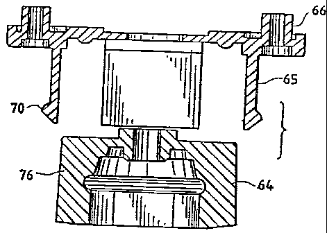
FIGS. 6 through 15 illustrate an embodiment of the unique valve
assembly 54 of the present invention. Referring initially to FIGS. 6 through
9,
the valve assembly includes a cam 64 and a collet 66. The cam 64 and the
collet 66 cooperate in connecting the valve assembly 54 to a canister, such as
the canister 53 discussed above.
The annular collet 66, illustrated in detail in FIGS. 11A through
11F, includes a plurality of cantilevered L-shaped fingers 65, which extend
generally perpendicularly from the collet. In these embodiments, four fingers
65 are spaced substantially evenly about the collet 66, at a common radial
distance from a center of the collet. Enlarged portions or pawls 70 extend
from
the fingers 65, at a distance from the base of the collet. The fingers 65 have
a
tapered leading edge 65a (FIG. 11B), a trailing-edge ridge 65b, and a notch
65c
between the edge 65a and the ridge 65b, the purpose of which will be described
below.
The collet 66 is fixed to the valve assembly 54. This can be
accomplished by a number of means, such as rivets, adhesive, or other like
well-known methods. In the preferred embodiment, the collet has a flange 66a
which fits into a matching groove (not shown) in the valve assembly 54. At
least one notch 66b is provided in the flange, into which a matching
protuberance in the groove fits, to keep the collet 66 from rotating. A
CA 02211379 1997-08-07
-20-
circumferential lip 66c abuts the valve assembly 54 and helps to prevent
lateral
movement of the collet 66. The circumferential lip 66c also acts to limit the
upward movement of the canister into the valve assembly 54.
As illustrated in detail in FIGS. 12A through 12F, the cam 64
has a noncircular, cylindrical receptacle 77, dimensioned to match the
noncircular, cylindrical pedestal 63 of the canister. The cam 64 sits within
the
collet 66 and is disposed to rotate relative to the valve assembly. This can
be
accomplished by any of several well-known mechanisms, such as connecting the
cam to the valve assembly with an outwardly extending lip 64a, as shown in
FIG. 10, or an inwardly extending lip 64a', as shown in FIG. 12B, which sits
in a matching groove (not shown) in the valve assembly 54. The cam rotates
about the valve probe 74, which extends from the valve assembly 54 partially
through the receptacle 77. Preferably, the receptacle 77 has an axis
coincident
with the valve probe 74. Disposed about the perimeter of the cam 64 are a
series of radially extending lugs 76. The lugs 76 can be uniform in cross
section, or be tapered as is apparent from FIG. 12B. Further, the lugs 76 can
each have a raised rib 76a, which corresponds to the groove 65c of each finger
65.
In operation, briefly, when the cam 64 rotates, the lugs contact
and force the collet fingers 65 outwardly, which causes the pawls 70 on the
collet fingers 65 to also spread outwardly - and into the annular groove 71 of
the canister cap 58. This locks the valve body 54 to the canister 53. Seals
can
be provided at contact points between the body 54 and canister 53, such as the
pair of seals 72, 73 best seen in FIGS. 10 and 13.
In more detail, before the valve assembly 54 is connected to the
canister 53, the collet 66 and cam 64 are disposed relative to one another as
shown in FIG. 14. At this point, the lugs 76 of the cam 64 are disposed in
gaps between the fingers 65 of the collet. The valve assembly 54 and the
canister 53 are first aligned with one another as shown in FIG. 10, so that
the
extended probe 74 is aligned with the depression or recess 75' in the seal 72
of
the cap 58. The valve assembly 54 and the canister 53 are then brought
together, and the probe 74 is inserted through the recess 75' in the canister
seal
CA 02211379 1997-08-07
-21 -
75, as best seen in FIG. 13. At this point, the hexagonal, cylindrical (in
this
embodiment) pedestal 63 of the canister 53 sits within the matching hexagonal,
cylindrical receptacle 77 in the cam 64.
In order to secure the connection, the canister 53 is twisted like a
screwdriver relative to the valve assembly 54. Because of the mating
noncircular, cylindrical pedestal 63 and receptacle 77, this twisting rotates
the
cam 64, which forces the lugs 76 of the cam 64 to contact the fingers 65 of
the
collet b6. The inner surfaces of the fingers 65 are disposed slightly closer
to
center than the outer surfaces of the lugs 76. Therefore, as the lugs contact
the
tapered edge 65a of the fingers 65, the fingers 65 will deflect outwardly. As
the lugs 76 slide into alignment with the fingers, the fingers will be spread.
The rotation of the cam 64 is complete when the lugs 76 abut against the
ridges
65b of the fingers 65. At this point, the ribs 76a of the lugs sit in the
grooves
65c of the fingers, providing resistance to accidental rotation of the cam 64
in
the opposite direction. FIG. 15 shows the relative positions of the lugs 76
and
the fingers 65' at this stage. As the fingers 65 spread, the enlarged portions
or
pawls 70 move outwardly and into the annular groove 71 in the cap of the
canister 53. Thus, the valve assembly 54 is locked to the canister 53, and
until
the canister is re-rotated in the opposite direction, the valve assembly 54
and
canister 53 remain locked together.
The above-described arrangement provides a highly reliable
connection, because the axis of the canister 53 (and thus the pedestal 63) is
now
coincident with the axes of both the cam 64 and the collet 66. This inventive
cam/collet arrangement promotes a more or less fully perimetric application of
force from the canister 53 to the cam 64 to the collet fingers 65, even if the
cross section of canister pedestal 63 and/or the receptacle 77 is not regular
polygonal in shape. Whether the receptacle 77 is hexagonal, cylindrical or
other noncircular, cylindrical shape, the rotational forces imparted by the
canister will be transferred by the cam at a plurality of locations about the
coincident axes, which promotes easy and complete seating of the pawls 70 in
the groove 71. Further enhancing the connection is the fact that the fingers
move only radially - and not circumferentially - because only the cam 64 -
CA 02211379 1997-08-07
-22-
and not the collet 66 - rotates. This promotes quick and secure seating of the
pawls 70 in the groove 71.
An alternate embodiment of the cam-and-collet mechanism is
shown in FIGS. 9B, 11G and 12G. The collet 66 is similar to the previously
discussed embodiments in many respects, but has an inwardly facing set of
threads 66d. The collet fingers 65 include inwardly extending pawls 70a
opposite the outwardly extending pawls 70. The collet 66 is fixed relative to
the valve assembly by any conventional means, such as a noncircular flange,
screws, rivets, adhesive, or the like.
The cam 64 sits within the collet and includes a set of threads
64b which mate with the threads 66d of the collet 66. In this embodiment, the
cam 64 does not include radially extending lugs, but instead has a contact
surface 64c on its leading edge.
In operation, as the cam 64 is rotated by the canister, the mating
threads 64b, 66d force the cam 64 to move axially relative to the collet 66.
As
the cam 64 moves in the direction indicated by arrow A in FIG. 9B, the contact
surface 64c will impinge upon the inwardly extending pawls 70a of the collet
fingers 65, forcing the fingers 65 to spread. As with the previously discussed
embodiments, this forces the outwardly extending pawls 70 into the groove of
the canister cap (not shown in these figures).
In the embodiment shown, both the inwardly extending pawls 70a
and the contact surface 70c are tapered. While these features improve the
interaction between these elements during operation, it is not necessary that
both or either of the pawl and the contact surface be so tapered.
While the valve assembly 54 of the present invention is
particularly well suited for use in combination with the LPG canister of the
present inventi8n, it will be appreciated that the unique cam-and-collet
design
provides for a simple push-and-twist attachment operation that can be employed
with other canisters, supply lines, and the like, as well. It will also be
appreciated that the cam/collet mechanism of the present invention can utilize
more or fewer lugs and fingers, which can also be spaced or sized differently.
It is not, for example, necessary that the lugs and fingers be evenly spaced
CA 02211379 1997-08-07
- 23 -
about the cam and collet, although this does provide the advantages describe
above. Also, the lugs and fingers can be shaped differently. For example,
rather than taper the fingers 65, the lugs 76 can be tapered; or the grooves
65c
and mating ribs 76a can be switched, so that the grooves are on the lugs 76
and
the ribs on the fingers 65.
Conduit
This portion of the invention is explained with reference to FIGS.
16 through 19. For example, FIG. 16 shows the lower right hand burner 52 of
FIG. 1 A. The conduit means 55 of FIG. 1 A includes two tubular conduits 78,
79 going from the valve assembly 54 (shown only fragmentarily in FIG. 16 -
and in the lower right corner) to the burner 52 (and to the "not shown" burner
52'). The conduit 78 extends from the valve assembly 54 to the right hand
burner in FIG. lA - this being the lower burner in FIG. 16.
The novel and advantageous construction of both conduits 78, 79
is exemplified by the conduit 78 depicted in FIGS. 16 through 18. Turning
first to FIG. 17 and starring at the outside, there is a protective braid 80
which
may be metal or plastic. In the illustration given, the braid 80 is
constructed of
metallic material, and the flexible tubing 81 is constructed of TEFLON. The
tubing 81 is packed with a solid, flexible plastic rod 82, such as a TEFLON'~
or rubber rod that is resistant to degradation in LPG. In one embodiment, the
conduit tubing 81 has an inner diameter of approximately 0.125" (about 3 mm)
and the plastic cylindrical rod has an outer diameter of approximately 0.010 -
0.015" less.
The purpose of the rod is to reduce the volume of the conduit
and to provide a large heat absorbing surface. It also causes a pressure drop
across the conduit. The combination of heat absorption and pressure drop helps
to produce consistent vaporization during lighting. An additional advantage of
the reduced volume is that burner control is improved. Changes in flow
settings will be more quickly reflected in burner output, because there will
be
less fuel in the conduit between the control valve and the burner.
CA 02211379 1997-08-07
-24-
The rigid conduits, which extend from the ends of the flexible
conduits 78, 79 to where these rigid conduits meet the frame 51, are also
partially filled with a solid rod. For example, the flexible conduit 78
connects
with a rigid conduit 84. See the central part of FIG. 16. The rigid conduit
lies
along and is supported by frame member 85. The conduit 84 connects to the
burner 52 as seen in FIGS. 16 and 19. In one embodiment, the solid rod in the
rigid conduit is brass rodding having an outer diameter of approximately
0.063"
(1.6 mm) with the brass tubing having an inner diameter of approximately
0.068" (1.7 mm). The packed brass conduits operate in the same fashion as the
packed flexible conduits.
The same structural arrangement applies for the brass (rigid)
conduit coupled to the flexible conduit 79 for delivering fuel to the other
burner
(not shown in FIGS. 16 and 19).
The rigid fuel conduit 84, for example, is connected to a brass
block 86 positioned below the burner air inlets (not shown). Fuel is conducted
through a passage in the brass block 86 to a generator tube 87 which extends
upwardly toward the burner flame zone. The tubular passage then goes through
the generator 83 and then downwardly back via tube 88 to the brass block 86.
Thereafter, the flow path continues through another passageway in the block 86
upwardly to a conventional orifice. The orifice discharges fuel, now a gas, to
a
conventional venturi and then the resulting fuel/air mixture flows to the
burner
for burning. The portion of the generator tube 87, 88 in the flame zone may be
provided with a heat sink plate - see the wider or enthickened portion 83 to
increase the transfer of heat from the flame to the generator and thereby
increase vaporization of fuel in the generator. Alternatively, the top portion
of
the generator may include a loop to increase the heat transfer area exposed to
the flame.
T6e Frame and Burners
Several of the accompanying figures illustrate a two burner stove.
If only one burner 52 is desired, only a single pair of support members 92, 93
need be employed. Unless otherwise noted, the following detailed description
CA 02211379 1997-08-07
-25-
of the various features of the collapsible frame applies to both single and
multiple burner stoves.
In a preferred embodiment of the collapsible stove as shown in
FIGS. 19, 1B, and 1C, a collapsible frame 51 includes two X-shaped support
members 92, 93 pivotally attached together at crossover points, or pivots 90,
91, of each support member 92, 93. Extending from each pivot 90, 91 are a
pair of opposing support legs 92a, 93a and a pair of opposing support arms
92b, 93b.
Refernng to FIGS. 21 and 1C, each X-shaped support member
92, 93 has a pivot 90, 91, shown here as an annular hub, through which a
portion of a burner assembly 52a extends. In the embodiment shown, the
burner assembly 52a serves as a pivot axis, about which one support member
92 pivots. A rigid fuel conduit 84, mounted on the other support member 93,
prevents the other support member 93 from pivoting about the burner assembly
52a. However, if the rigid fuel conduit 84 were not mounted on the support
member 93, both support members 92, 93 could pivot about the burner
assembly 52a. Although in the present embodiment both support members are
(or potentially are) pivotally attached to the burner assembly 52a, a similar
collapsible frame could be constructed by fixedly attaching a first support
member to the burner assembly, and pivotally attaching a second support
member to either the burner assembly or the first support member.
Pivots 90, 91 of support members 92, 93 each include a rotation
limiter 90a, 91a. As illustrated in FIG. 1C, the rotation limiter 90a, on the
uppermost support member 92, extends downwardly. The rotation limiter 91a,
on the lowermost support member 93, extends upwardly. Each rotation limiter
90a, 91a is positioned along the outer circumference of the respective pivot
90,
91 so that when the frame S 1 is in the operating configuration, the rotation
limiter 90a, 91a of each support member 92, 93 abuts against the other support
member 93, 92. Accordingly, the rotation limiters 90a, 91a restrict the amount
that the support members 92, 93 can pivot relative to one another. In a
preferred embodiment, the rotation limiters 90a, 91a permit the support
members 92, 93 to pivot approximately 90° relative to one another.
CA 02211379 1997-08-07
-26-
By integrating two or more frames of the above-described type,
additional burners can be accommodated. For example, in the two burner
embodiment shown in FIGS. lA, 20, and 21, two pairs of pivotally connected
X-shaped support members 92, 93, 92', 93' are arranged in quadrilateral
relation to provide burners 52, 52' at two opposing corners and pivots at the
other two "non-burner" corners 94, 95. Reference to FIG. 20 (and also FIG.
1 A) reveals that the two burner frame 51 is generally rectangular when
uncollapsed. In this uncollapsed or operating configuration, the support
members 92, 93, 92', 93' cooperate to provide a stable base for the stove 50.
In a collapsed configuration, shown in FIG. 2, in which the support members
92, 93, 92', 93' are juxtaposed in a compact arrangement, the frame 51 has a
narrow elongated shape that is suitable for transport in a backpack or the
like.
The compactness of the frame 51 can be appreciated from the sequence of
views in FIGS. 22 through 26. Opposing support members 92 and 92', 93 and
93' remain substantially parallel to one another as the frame moves between
the operating and collapsed configurations.
In the single burner embodiment, the support legs 92a, 93a and
support arms 92b, 93b are of equal length. See FIGS. 1B and 1C. In the two
burner embodiment, a support leg 92a, 92a' and corresponding support arm
92b, 92b' of two opposing support members 92, 92' have an extended portion,
the distal end of which is attached with a pivot pin to a corresponding
portion
of an adjacent support member 93', 93. See FIG. 20. However, a two burner
collapsible frame could have support members 92, 93, 92', 93' all of equal
length. Likewise, a single burner collapsible frame could have support
members 92, 93 of unequal length.
Advantageously, the support members may be constructed of
lightweight metal, preferably magnesium alloy or aluminum alloy. However,
depending upon usage and other physical conditions, other materials may be
suitably employed. As shown in FIGS. lA and 2, to further reduce the weight
of the frame 51, material may be removed from the inside of the support
members by reducing the thickness or creating through-holes in the support
CA 02211379 1997-08-07
-27-
arms and legs. The support members can be formed by any conventional
means, and are preferably formed by die casting.
In the operating configuration, the support arms 92b, 93b
cooperate to form a cooking utensil support. As shown in~ FIG. 1 A, each
support arm 92b, 93b has a series of steps 100 to optimally support pots,
pans,
or other cooking utensils. The steps 100 increase in height above the ground
or
other support surface as they are located farther from the pivot center 90, 91
of
the frame 51. Also, the steps 100 may slope down toward the pivot center 90,
91, i.e., the center of the pot, pan, vessel or other cooking utensil, to
provide
greater stability. In the illustration given, four steps 100 are provided to
accommodate different size pots, pans, vessels or other cookery utensils.
However, fewer or more steps can be provided depending on the intended
application of the stove. The steps shown in this embodiment are merely for
purposes of illustration. Equivalently, the steps could be a series of raised
bumps on the support arms or a series of notches formed in the support arms.
Those skilled in the art will appreciate the various other possible
configurations
of steps.
In a preferred embodiment, rather than integrally forming steps
on the support members, grate wires similar to wires 152a shown in FIG. 27
are employed. FIGS. 1B and 1C illustrate how such grate wires 92c, 93c are
mounted on the support members 92, 93. Each grate wire slopes toward the
center of the stove and has a series of spaced notches 92d, 93d formed therein
for stabilizing cooking utensils of different sizes. The grate wires
preferably
are constructed of stainless steel. Alternatively, the grate wires can be
formed
of plated steel, or other materials capable of withstanding the high
temperatures
encountered during use. The grate wires are mounted to the support members
by pressing, crimping, pinning, bonding or other attachment techniques. By
using grate wires in this manner, less heat is conducted to the frame than
when
the support members directly support a cooking utensil. This is especially
advantageous when the support members are formed of a highly heat-conductive
material such as an aluminum or magnesium alloy.
CA 02211379 1997-08-07
-28-
In the single burner embodiment, a rigid fuel conduit 84 rests
against one support leg 93a of the burner frame 51. A bracket 93e extends
from the support leg 93a to hold the rigid fuel conduit 84 against the support
leg 93a. See FIGS. 19 and 1C. In the two burner embodiment, "non-burner"
corner 95 serves as the entry of the flexible fuel conduits 78, 79. A bracket
92e' on one extended support leg 92a' holds a rigid fuel conduit 96 for
burner 52'. A bracket 93e on the adjacent support leg 93a, which is pivotally
attached to the extended support leg 92a', holds another rigid fuel conduit 84
for burner 52. With the two burner frame 51 is folded into a relatively
compact or "flat" configuration, the rigid fuel conduits 84, 96 are
substantially
parallel, with their ends remote from the burner assemblies 52a, 52a'
protruding slightly from the folded frame 51. This arrangement permits the
flexible fuel conduits 78, 79 and the valve assembly 54 to fold over the
collapsed frame 51 for compact storage.
The burner 52 of FIG. lA is equipped with a 360° unitary,
bowl-shaped wind screen 89. See also FIGS. 19 and 21. The wind screen is
positioned between the burner 52 and the support member pivots 90, 91. See
FIGS. 20, 21, and 1C.
Alternatively, the burner 52 may be equipped with a segmented,
bowl-shaped wind screen 89a. See FIGS. 2 and 22 through 26. The wind
screen 89a is constructed of four curved segments 97, 98, 97', 98', or
quadrants, each of which is attached to an appropriate support member. In
accordance with this arrangement, each wind screen segment can rotate with a
respective support member to provide a compact storage configuration. Rather
than attaching each wind screen segment to an appropriate support member,
another arrangement may have an opposing pair of segments attached to one
support member, and the other opposing pair of segments attached to the burner
assembly itself. The general compactness of the frame and wind screen can be
appreciated from the sequence of views shown in FIGS. 22 through 26. In
FIG. 26, the wind screen segments are virtually completely stacked, or
overlapping, i.e., each upper segment 97, 9T almost eclipses the associated
lower segment 98, 98'. In the operating configuration shown in FIG. 22, the
t
CA 02211379 1997-08-07
-29-
gap 99' between the upper and lower segments 97, 98 is virtually nonexistent.
At a preliminary stage of folding shown in FIG. 24, there is a gap 99 of about
20°. In the completely collapsed configuration shown in FIG. 26, the
gap 99"
is almost 90°.
In order to properly position the support members 92, 93 relative
to the burner assembly 52a, a helical spring 52b is provided on the burner
assembly 52a below the support members 92, 93. The spring 52b urges the
support members 92, 93 toward the underside of the burner 52.
Understandably, the wind screen 89 tends to become hot when
the stove is operated. To reduce the heat transferred from the windscreen 89
to
the support members 92, 93, a "corrugated" washer 52c may be interposed
between the windscreen 89 and the uppermost support member 92. See FIG.
1C. The "waves" in the washer 52c reduce the surface contact and
consequently the heat transferred from the windscreen 89 to the support
members 92, 93. Other devices or arrangements, such as an insulative washer
formed of heat insulating material can be used to reduce the transfer of heat
from the wind screen to the support members.
Second Connector Embodiment
Reference is now made to FIGS. 27 through 29. At the outset it
will be understood that this embodiment may be used with either circular or
noncircular cylindrical pedestals. Two alternative features of the invention
are
illustrated. First, in FIG. 27, there is a single burner form of camp stove -
seen mounted directly on the canister 153, i.e., without the interposition of
flexible conduit means. However, conduit means are provided as part of a
valve assembly 154, which advantageously provide the promotion of
vaporization of the conduits, etc., of the first described embodiment.
The burner 152 is equipped with U-shaped supports for
supporting a pot, pan, vessel, cooking utensil or the like. The canister 153
is
equipped with a cap 158. See also FIG. 28. Positioned immediately above the
cap 158 is the valve assembly 154. The burner 152 is rigidly carried by the
' CA 02211379 1997-08-07
-30-
valve assembly 154. What is especially novel and advantageous is the
connection between the valve assembly 154 and the cap 158.
This embodiment also employs a collet-type member 166 -
better seen in FIG. 29 - and a cam member 164 also seen in perspective in
FIG. 29. The cam member 164 also has associated therewith the probe 174 -
carried by the valve assembly 154 in fixed relation to the cam member 164
which is also rigidly mounted on the valve assembly 154.
Differing from the first embodiment is the fact that the collet
member 166 is provided as part of the cap 158. The cap 158 again has the
inwardly facing annular or circumferential groove 171 into which an annular
rib
170 (corresponding to the pawls 70 of the first embodiment) provided on the
collet 166 is received.
As the cam member 164 is brought toward engagement with the
collet member 166 carried by the cap 158 - the condition depicted in FIG. 29
- the radially outwardly extending lugs 176 on the pan member 164 are
aligned with the open ends of the L-shaped slots 101 provided in the fingers
165. These fingers 165 in collet-like fashion are separated by axially-
extending
slots or separations 101.
As the lugs 176 engage the L-shaped slots 101, they follow the
slot contour as the canister 153 is rotated. Again, the canister is provided
with
a stepped pedestal 163 where the lower step 163a is non-circular. Again, in
the
illustration given, a hexagonal shape is employed - to match opening 177 in
the cam member 164. As the canister is rotated relative to the valve assembly,
or vice versa, the lugs 176 move further down the L-shaped slots 101 which
become shallower - developing a more secure seat of the cam member 164
(and therefore the valve assembly 154) in the collet member 166 (and therefore
the cap 158 of the canister 153). This results in two advantageous functions.
First, the fingers 165 are forced outwardly - further seating the annular rib
170 in the annular recess 171. Second, this brings the probe 174 downwardly
through the web 175 - more particularly, the orifice 175' - to effectuate a
secure seal.
_. CA 02211379 1997-08-07
-31-
Third Connector Fanbodiment
The third embodiment is seen in FIGS. 30 through 32. At the
outset it will be understood that this embodiment also may be used with either
circular or noncircular cylindrical pedestals. This embodiment has the collet
and cap combined and also provides the same vaporization promoting operation
downstream of the canister.
In each of FIGS. 30 and 31, reference numeral 253 designates
the canister equipped with a rolled-on cap 258. The cap is equipped with a
centrally apertured boss 263 somewhat akin to the pedestal of the preceding
embodiments. The boss 263 has fitted therein a seal 275 having a recessed
thinner area 275' . This is engaged by the probe 274 provided as part of the
lower housing 264 of the valve assembly generally designated 254. Seen only
in FIG. 30.
The lower housing 264 is equipped with a pair of opposed lugs
276 which are engageable with a pair of opposed camped slots 201. As the
lugs enter the slots, relative turning movement (e.g., a 1/4 turn) of the
valve
assembly and canister cap results in the parts being pulled together, the
probe
274 rupturing the thin web 275' and the lugs being temporarily locked by the
detent 202 adjacent to, but spaced from, the lower end of each slot 201. This
results in the two parts, i.e., canister cap 258 and valve assembly 254,
remaining connected. And when disconnection is indicated, all that is required
is a reverse 1l4 turn, for example.
To provide a greater engagement or entry of the lower housing
into the cap, the modification of FIG. 32 may be employed. There, all the
parts
are the same except the vertical wall of the cap is lengthened and has a
rolled
top - as at 258'. Also, the camped slot is different. In FIG. 32, the slot
201'
is seen to have its upper terminus in the rolled upper edge of the cap, rather
than the flared upper edge of the FIG. 31 embodiment. In either event, the
same advantageous operation relative to promoting flow path vaporization is
available.
CA 02211379 1997-08-07
-32-
Alternate Frame Embodiment
FIGS. 34A through 34D illustrate another embodiment of the
stove frame S 1, which includes three pivotally connected support legs 191,
192,
193. The legs 191, 192, 193 extend, respectively, from annular pivots 194,
195, 196 with openings 194a, 194b, 194c, through which the burner assembly
52 is secured. Support leg 191 includes a bracket 196, which is provided to
hold the rigid fuel conduit 84 against the support leg 191, essentially fixing
the
support leg 191 to the burner assembly.
In order to facilitate collapsibility of the frame 51, the support
leg 192 extends approximately radially from the annular pivot 195, while
support legs 191, 193 are askew relative to the annular pivots 194, 196,
respectively. The support legs 191, 193 are offset from the annular pivots
194,
196 in opposite directions. That is, when viewed from above with the support
legs 191, 193 oriented similarly, annular pivot 194 will be offset to one side
of
support leg 191, while annular pivot 196 will be offset to the other side of
the
support leg 193. In the embodiment shown, when the frame 51 is assembled,
annular pivot 194 is stacked on top of annular pivot 195, which is, in turn,
stacked on top of annular pivot 196. A rotation limiter 192a (discussed below)
on support leg 192, prevents the support legs 191, 193 from pivoting beyond a
certain degree away from the support leg 192. This permits the legs to be
collapsed against one another in only one direction. Thus, when the frame 51
is collapsed, support legs 191, 193 lie closely against opposite sides of
support
leg 192.
Support legs 191, 193 are also offset vertically relative to annular
pivots 194, 196, respectively. When viewed from the side, annular pivot 194
extends from a higher point on support leg 191 than does annular pivot 195
from support leg 192, which is in turn higher than annular pivot 196 is
relative
to support leg 193. This permits the legs 191, 192, 193 to be at a
substantially
common height when the annular pivots 194, 195, 196 are stacked when the
frame 51 is assembled.
The rotation limiter 192a extends from annular pivot 195
opposite the support leg 192. This limiter 192a extends above and below
CA 02211379 1997-08-07
-33-
annular pivot 195, and is dimensioned to contact each of the other support
legs
191, 193 when they are pivoted approximately 120° away from support leg
192. This defines a fully-open position, shown in FIG. 34A, in which the
support legs 191, 192, 193 are approximately evenly distributed about the
burner assembly 52. Because the support legs 191, 193 are offset relative to
annular pivots 194, 196, respectively, the limiter 192 can be relatively small
and still maintain the separation between these support legs 191, 193. In the
embodiment shown, for example, the annular pivot 195 has an outer radius of
approximately 0.60", and the limiter 192a is only approximately 0.37" across
its widest portion, which is approximately 0.70" from the center of the pivot
195. It is not necessary that the stove be designed so that the support legs
191,
192, 193 will be evenly separated when the stove is fully open. Any desired
separation can be achieved by altering the size and location of the limiter
192a.
One particular advantage of this configuration is the ease with
which the frame 51 can be opened and collapsed. From the collapsed position,
with the support legs 191, 192, 193 lying closely against one another, a user
need only grasp and rotate support leg 193 about the burner (clockwise, when
viewed from above, in the illustrated embodiment) away from support leg 191
as far as possible to open the stove. As support leg 193 rotates to
approximately 120° away from support leg 192, it will contact the
limiter 192a.
Further rotation of the support leg 193 in the same direction will force the
limiter 192a, and therefore the support leg 192, to rotate in the same
direction
relative to the support leg 191. This continues until the limiter 192a
contacts
the support leg 191, at which point the stove will be in the illustrated,
fully-
opened positioned. To close the stove, support 193 is simply rotated about the
burner assembly 52 in the opposite direction (counterclockwise, when viewed
from above, in the embodiment shown).
Summary
The invention of an LPG canister connector for a combustion
appliance 52, 52' includes means providing a flow path from a canister 53,
153, 253 containing liquid fuel and having a cap 58, 158, 258 with outlet
CA 02211379 1997-08-07
-34-
means at the upstream end of the flow path, a valve assembly 54, 154, 254
adapted to be connected to the cap and equipped with conduit means adapted to
be connected to a combustion appliance 52, 52', 152 at the downstream end of
the flow path, the flow path means being equipped with means for promoting
vaporization of the fuel intermediate the ends of the flow path.
The vaporization promoting means may take a variety of forms.
For example, the most upstream position for this to occur is in the valve
assembly 54, 154, 254. In addition to the aluminum or other metal body which
makes up the valve assembly, other heat sink producing structures may be
. employed such as the fins 69.
Another example of the vaporization promoting means are the
flexible and rigid conduits. By "packing" them, it is reasonably convenient to
achieve a large heat absorbing surface and a reduction of volume in the flow
path downstream of the canister, viz., lower flow rates.
Still further, the use of metal in junctions, particularly when flow
directions change, can be helpful in promoting vaporization of the last
vestiges
of liquid. Exemplary of this are the block 86 and the generator 83.
The invention, as indicated above, finds use in connection with
lanterns - particularly the mantle type which operates advantageously on
liquid
fuel. There, we interpose thermal insulation in the flow path between the
generator and the burner tip or jet. This promotes vaporization prior to the
burner in a configuration generally like that of FIG. 27. A suitable burner
for
the lantern and the other embodiments hereof can be seen in British Patent 2
262 157B.
While in the foregoing specification a detailed description of
embodiments of the invention have been set down for the purpose of
illustration
and compliance with the statute, many variations in the details herein given
may
be made by those skilled in the art without departing from the spirit and
scope
of the invention as defined by the following claims.