Note: Descriptions are shown in the official language in which they were submitted.
CA 02211~01 1997-07-2~
16616
METHOD AND APPARATUS FOR ~AKTr~
WIDE MOUTH HOLLOW GLASS ARTICLES
This invention relates to a method and apparatus for
making wide mouth hollow glass articles.
Background and Su_ ary of the Invention
Commercial glass container forming processes employ
s two stages: (1) a blank mold to form a preliminary shape called
a parison from a gob, and (2) a finish or blow mold, where the
parison is expanded with compressed air to conform to the cavity
shape. Various patents have been directed to utilizing plural
neck rings and plural molds in an effort to increasing the
lo efficiency, as shown in United States patents 3,198,617 and
3,434,820.
These patents disclose processes that are similar.
Both utilize three coupled neck rings to transfer the glass
between stations. The rings move simultaneously at the same
velocity. Patent 3,434,820 discloses a chain operated neck
ring carrier, while 3,198,617 mounts the rings on a rotary
turret. Patent 3,434,820 delivers the gob to the blank, then
moves the blank mold under the neck ring and plunger, while
patent 3,198,617 loads the blank mold through the neck ring and
moves the plunger into pressing position above the ring. Patent
3,434,820 opens the ring to deposit the formed container on the
CA 02211~01 1997-07-2~
dead plate or conveyor with the carrier in motion, while patent
3,198,617 opens the ring after the rotary turret index portion
has been completed.
The blank mold pulls away from the formed parison as
the plunger retracts. When the blank mold clears the parison
and the plunger clears the first neck ring, the ring transfers
the parison to the blow mold. For an efficient operation, the
parison reaches the blow mold just as it is closing. Before
the take out mechanism can remove the bottle from the blow mold,
the blow head must be retracted and the mold must be partially
open, and it must remain open until the container clears. The
second ring must arrive at the pressing position before the
blank mold moves into pressing position. The cavity rate can
be increased by reducing the neck ring transfer times. (Speed,
or cavity rate, in units per cavity per minute is equal to 60
divided by the blank or mold cycle time in seconds. The blank
and mold cycle times are equal).
Among the objectives of the present invention are to
provide a method and apparatus for making wide mouth hollow
20 glass articles wherein the productivity and process stability
is increased while using comparable forming times and mechanism
times; which maintain required glass contact times and mechanism
times, while reducing the blank mold and blow mold cycle times
and increasing parison transfer time; wherein the finish is
25 held in the neck ring until the mold blow opens to prevent the
CA 02211~01 1997-07-2~
~ ,
container from pulling to one side and causing checks in bottom
and/or base of neck; wherein machine speed is increased by using
two neck rings to minimize parison transfer and reheat time
appearing in the blank mold and blow mold cycles; wherein the
blank and mold cycle times are equal; wherein the total parison
reheat time can also be decreased while maintaining sufficient
parison elongation; and wherein the blow mold can be located
under the blank mold without altering the basic method.
In accordance with the invention, the method of forming
o a hollow glass article comprises delivering a gob of glass to
a blank mold, providing a first neck ring to a position adjacent
the blank mold, forming the gob in the blank mold into a parison,
moving the first neck ring to transfer the parison to a blow
mold, blowing the parison in the blow mold to form a hollow
article, releasing the engagement of the first ring relative
to the blow mold with the hollow article, moving the first neck
ring away from the blow mold, removing the hollow article from
the blow mold, returning the first neck ring to a position
adjacent the blank mold to repeat the cycle, providing a second
neck ring adjacent the blank mold while the first ring is moving
toward the blow mold, delivering a second gob of glass to the
blank mold while the second ring is in position adjacent the
blank mold, forming the second gob into a second parison, moving
the second parison to a position adjacent the blow mold while
the first neck ring is being returned to a position adjacent
CA 02211~01 1997-07-2~
said blank mold; and controlling the positioning and movement
of the first neck ring and second ring independently of one
another such that the velocity and movement of each neck ring
is varied without affecting the overall forming cycle.
An apparatus for forming a hollow glass article
embodying the invention comprises a blank mold, a blow mold,
means for delivering a gob of glass to a blank mold, a first
neck ring, means for moving said first mold between a position
adjacent the blank mold and a position adjacent a blow mold,
o means for forming a gob in the blank mold into a parison, a
second neck ring adjacent the blank mold, means for moving the
second ring between a position adjacent the blank mold and a
position adjacent the blow mold, means for removing a hollow
article from the blow mold, each said means for moving said
first ring and means for moving said second ring being controlled
independently of the other such that the velocity and movement
of each neck ring is varied without affecting the overall forming
cycle and such that the reheat and transfer time of each neck
ring is controlled independently of the other neck ring.
The cycle of the present invention utilizes two
independently operated neck rings, with a conventional take out
mechanism. Since the rings have individual operating mechanisms,
they can start and stop independently and move at different
velocities. This allows more flexibility in the process, since
the reheat and run time can be varied without affecting the
CA 02211~01 1997-07-2~
machine speed. After the blank and plunger are clear, the first
ring transfers the parison to the blow mold. When the blow
head retracts, the second ring releases the container and the
mold opens. Then, the second ring moves to the pressing station
and the take out removes the formed container from the mold.
The mold cannot close until the bottle clears and the first
ring arrives with the parison, and the blank mold cannot move
up until the second ring is in pressing position.
CA 02211~01 1997-07-2~
Description of the Drawings
FIGS. l through 6 are partly schematic sectional views
showing the sequence of operations for the method and apparatus
embodying the invention.
FIG. 7 is a fragmentary elevational view of a multiple
cavity apparatus embodying the invention.
FIG. 8 is an end view of the apparatus shown in FIG. 7.
FIGS. 9A and 9B are elevational views of the apparatus
in different operative positions.
lo FIG. lO is a plan view of a portion of the apparatus
shown in FIGS. 7, 8, 9A, 9B.
FIG. ll is a forming cycle of an apparatus embodying
the invention.
FIG. 12 is a forming cycle of a prior art I.S.
apparatus.
CA 02211~01 1997-07-2~
\
Description of the Preferred Embodiment
In accordance with the invention, the method of forming
a hollow glass article comprises delivering a gob of glass to
a blank mold, providing a first neck ring in a position adjacent
the blank mold, forming the gob in the blank mold into a parison,
moving the first neck ring to transfer the parison to a blow
mold, blowing the parison in the blow mold to a hollow article,
releasing the engagement of the first ring with the hollow
article, moving the first neck ring away from the blow mold,
o removing the hollow article from the blow mold, returning the
first neck ring to a position adjacent the blank mold to repeat
the cycle, providing a second neck ring adjacent the blank mold
while the first ring is moving toward the blow mold, delivering
a second gob of glass to the blank mold while the second ring is
in position adjacent the blank mold, forming the second gob into
a second parison, moving the second parison to a position
adjacent the blow mold while the first neck ring is being
returned to a position adjacent said blank mold; and controlling
the positioning and movement of the first neck ring and second
ring independently of one another such that the velocity and
movement of each neck ring is varied without affecting the
overall forming cycle.
An apparatus for forming a hollow glass article
embodying the invention comprises a blank mold, a blow mold,
means for delivering a gob of glass to a blank mold, a first
CA 02211~01 1997-07-2~
neck ring, means for moving said first mold between a position
adjacent the blank mold and a position adjacent a blow mold,
means for forming a gob in the blank mold into a parison, a
second neck ring adjacent the blank mold, means for moving the
second ring between a position adjacent the blank mold and a
position adjacent the blow mold, means for removing a hollow
article from the blow mold, each said means for moving said
first ring and means for moving said second ring being controlled
independently of the other such that the velocity and movement
o of each neck ring is varied without affecting the overall forming
cycle and such that the reheat and transfer time of each neck
ring is controlled independently of the other neck ring.
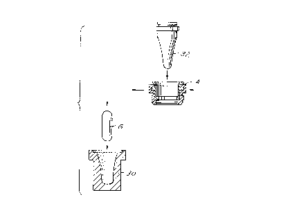
Referring to FIGS. 1-6, which diagrammatically show
the method, the method comprises the use of a blank mold 30 and
a sectional blow mold 31, a plunger 32, as in conventional I.S.
glass forming machines, and two sectional neck rings A, B. The
blank mold 30 and blow mold 31 may be single cavity or multiple
cavity.
The description of the present invention applies to
a top loading, upright, one piece press-and-blow blank mold,
but other variations are possible such as the use of a segmented
mold. Multiple cavity operation is contemplated.
The steps of the method are summarized as follows:
CA 02211~01 1997-07-2~
.
FIG. 1: A glass gob G is loaded into the blank mold
30 while neck ring "A" is in the press position, or is moving
into press position, and the plunger 32 is retracted.
FIG. 2: The blank mold 30 moves relatively upward
to engage the neck ring "A", and the plunger 32 is extended
downward through the ring "A" to press the gob G into a parison P.
FIG. 3: The blank mold 30 pulls relatively away from
the parison P on the neck ring A and moves to a loading position
as the plunger 32 is retracted. When the blank mold 30 clears
lo the formed parison P and the plunger 32 clears neck ring "A",
the ring "A" moves toward the blow mold 31. Neck ring "B"
releases the previous container after the mold 31 starts to
open and neck ring "B" moves toward the press position before
the take out tongs T move in to remove the container from the
blow mold 31.
FIG. 4: Neck ring "B" moves into the press position
as the next gob G is loaded into the blank mold 30. Neck ring
"A" with the parison P therein lowers to the final blow position
as the blow mold 31 closes and the blow head H moves in. The
parison P reheats and elongates from the time the blank retracts
until final blow air is applied.
FIG. 5: Compressed air is applied through the neck
ring "A" to expand the parison P and form a container C.
FIG. 6: Neck ring "A" releases the finish after the
2s blow mold 31 starts to open. Finally, neck ring "A" clears the
CA 02211~01 1997-07-2~
mold before the take out tong T moves in to engage the finish,
and neck ring "A" shifts to the press position to repeat the
cycle. The container C is transferred to the dead plate for
additional cooling.
Referring to FIGS. 7, 8, 9A, 9B and 10 the method is
shown as applicable to an apparatus with multiple cavities
wherein corresponding parts have been indicated with the suffix
"a".
FIGS. 7, 8, 9A and 9B show apparatus which can be used
to perform the method and make multiple containers in each
cycle. As shown in FIG. 7, previously formed multiple parisons
P are being transferred from multiple cavity parison mold 30a
by multiple neck rings Aa to the multiple cavity blow mold 31a.
During this transfer, multiple neck rings 36 are being returned
into position adjacent the blank mold 30 after having released
previously formed containers at the blow molds 31a. As further
shown in FIGS. 9A, 9B and 10, multiple neck rings Aa are provided
on a first shuttle 33 movable on a slide 34 by an elevated servo
driven mechanism. Similarly, multiple neck rings Ba are provided
on a second shuttle Bb movable on a slide 37 by a servo. At
the parison forming station, cylinders 40 move the multicavity
parison molds 30a upwardly into position for pressing the
parisons P by plungers 32a and downwardly out of position to
permit shunting of the neck rings Aa, Ba. Similarly, the blow
molds Ba are moved vertically into and out of position by
--10--
CA 02211~01 1997-07-2~
.
cylinders. As shown in FIGS. 7 and 8, the neck rings Aa, Ba
move only horizontally and the parison molds 30a and blow molds
31a move upwardly into and out of position with respect to the
neck rings Aa, Ba. Tongs T are similarly mounted on a shuttle
45 movable on a slide 46 by a servo mechanism.
The cycle of the present invention utilizes two
independently operated neck rings, with a conventional take out
mechanism to remove the bottle from the mold. Since the rings
have individual operating mechanisms, they can start and stop
lo independently and move at different velocities. This allows
more flexibility in the process, since the reheat and run time
can be varied without affecting the machine speed. After the
blank and plunger are clear, the first ring transfers the parison
to the blow mold. When the blow head retracts, the second ring
releases the container and the mold opens. Then, the second
ring moves to the pressing station and the take out removes the
formed container from the mold. The mold cannot close until
the bottle clears and the first ring arrives with the parison,
and the blank mold cannot move up until the second ring is in
pressing position.
Referring to FIGS. ll and 12, the forming or timing
cycle of a wide mouth glass container forming apparatus embodying
the invention is shown in FIG. ll and the forming or timing
cycle of a prior art wide mouth glass container forming apparatus,
CA 02211~01 1997-07-2~
known as an I.S., is shown in FIG. 12. In these diagrams, the
definitions are as follows:
PD - Plunger down
PU - Plunger up
MO - Mold open
MC - Mold close
BHU - Blow head up
BHD - Blow head down
TOI - Take out in
TOO - Take out out
NRO - Neck ring open
NRl - First neck ring
NR2 - Second neck ring
NR20 - Second neck ring open
It can be seen that the timing cycle of the present
invention requires less time to execute than an equivalent I.S.
cycle with comparable mechanism and forming times. The cycle
of the present invention maintains required glass contact time
while reducing blank mold and blow mold cycle times and increasing
parison transfer time.
It can thus be seen that there has been provided a
method and apparatus for making wide mouth hollow glass articles
wherein the productivity and process stability is increased by
using comparable forming times and mechanism times; maintaining
required glass contact times and mechanism times while reducing
CA 02211~01 1997-07-2~
the blank mold and blow mold cycle times and increasing parison
transfer times; wherein the finish is held in the neck ring
until the mold opens to prevent the bottle from pulling to one
side and causing checks in the bottom and/or base of the neck;
wherein machine speed is increased by using two neck rings to
minimize parison transfer and reheat time appearing in the blank
mold and blow mold cycles; wherein the parison reheat time can
also be decreased while maintaining sufficient parison
elongation; and wherein the blow mold can be located under the
o blank mold without altering the basic method.