Note: Descriptions are shown in the official language in which they were submitted.
, CA 02211611 1997-07-2~
TOOL FOR ROLL CRIMPING A FLANGE COVER
BACKGROUND ON THE INVENTION
1. Technical Field
This invention generally relates to a tool and method for crimping a flange cover onto a
flange and, more particularly, to a tool and method for roll crimping a flange cover or sealing strip
to a flange at an opening to a vehicle body.
5 2. Discussion
Openings in a vehicle body, such as a door opening or a tr~nk opelling, often contain
several flanges which are welded together to join an interior panel or reinforcement, ~ith an
exterior body panel of the vehicle. These flanges are often exposed when the door or trunk is
opened and are commonZy covered by 2 flange cover to improve the aesthetic appearance, or are
I û covered using a sealing strip which improves both the aesthetic appearance and provides a sealing
surface which is used to prevent water or other environmental conditions from entering the
interior of the vehicle or the trunk, as the case may be.
It is cornmon within the industry to have the flange cover formed in a generally U-shaped
configuration such that the mouth of the U is generally the same width as the thickness of the
15 flanges which it will cover. Tnct~ tion of the flange cover in this condition is oflen difficult since
the cover must be forced over the flanges. This operation is commonly done by hand, and may
result in variations of the flange cover height relative to the flange. Further, it is important that
the flange cover be tight to the flange on both sides of the flange, since the friction between the
flange cover and the flange is the primary or sole means of retention.
CA 02211611 1997-07-2~
The invention disclosed and described herein reduces or resolves several of the
disadvantages encountered with the current method of installation as described above.
SUMMARY OF THE INVENTION
In accordance with the t~ching~ of the present invention, there is provided a tool having
5 a body from which extends a first roller having a fixed axis, and a second roller having a fieely
floating axis which remains parallel to the fixed axis of the first roller. A first biasing means urges
the first and second roller to a closed position wherein the rollers are nearer to o ne another. A
driving means is connected to the tool either directly or remotely, such that the first and secord
roller are rotatingly driven.
BRIEF DFSCRIPTION OF THE DRAWINGS
The various advantages ofthe present invention will become apparent to orie shiiled ir ehe
art upon reading the following specification and by reference to the drawings in whlch:
- - FIG. I is a side elevation view of a preferred embodiment s)f the present invenLion as
utilized on a typical automobile door opening;
FIG. 2 is a sectional view s)f a flange cover positioned on the flange of the door opening
in Figure 1 prior to being crimped by a tool made in accordance with the teachings of the present
invention;
FIG. 3 is a sectional view of a flange cover positioned on the flange of the door opening
in Figure I after being crimped by a tool made in accordance with the teachings of the present
20 invention;
FIG. 4 is a perspective view of a preferred embodiment of the present invention;
CA 02211611 1997-07-2~
FIG. 5 is a perspective view of a second preferred embodiment of a tool made in
accordance with the teachings of the present invention;
FIG. 6 is a partial sectional view through a preferred embodiment of the present invention
shown in an open position; and
FIG. 7 is a partial sectional view through a preferred embodiment of the present invention
shown in a closed position.
DETAlLED DESCRIPTION OF THE I'REFERRED E~ ODIMENTS
The following description ofthe plefelled embodiments is merely exemplary in nature and
is in no way intended to limit the scope ofthe inventic)n, i~s application, or its uses.
Referring to Figure l, there is sho~l a first prefened embodiment of the roll crimping tool
l 0 made in accordance with the teachings of the present invention. The crimping tool l 0 is used
to secure a flange cover 12 to a weld flange or flanges 14 which are typically !ocated in an
opening 16 of a vehicle body 18. Examples of such openings include, but are not limited to, the
front and rear door openings, a trunk opening, or a liftgate opening.
l 5 As shown in Figure 2, the flange cover 12 is generally comprised of an extluded plastic
or rubber retention portion 20 within which is embedded a core 22. The core 22 of a flange cover
12 utilized in conjunction with crimping tool l 0 may be either a stamped metal core, a wire mesh
core, or any other core constmction which when compressed along its leg portions 24 and 26 will
substantially remain in such a compressed state by being permanently deformed, as opposed to
plastic deformation wherein the material returns to its prior formation after being acted upon by
the compressive forces. This permanent deformation increases the retention forces between the
flange cover 12 and flange 14, thereby securing flange cover 12 to flange 14.
CA 02211611 1997-07-2~
The flange cover 12 is originally presented to the flange 14 in an open condition as shown
in Figure 2. This open condition allows an operator to easily position the flange cover 12 around
the entire periphery of the opening 16 (shown in Figure I ) and onto the flange 14 pnor to fully
securing the flange cover 12 to flange 14 by using crimping tool 10. The open condition is
S created by having the leg portions 24 and 26 of the generally U-shaped flange cover 12 initially
formed at an angle greater than 90 degrees relative to the web 28 of the flange cover 12.
Figure 3 shows the'flange cover of Figure 2 after being positioned on flange 14 and being
- crimped by crimping tool 10. Leg portions 24 and 26 of the U-shaped flange cover 12 are forced
to a generally parallel condition with flange 14, and retention portion 20 is forced to sscvrely
contact flange 14 by core 2~ having been permanently deformed by the closing forces of crimping
. tool 10. This secure c.ontac.t between retentioll portion 20 and flange 14 provides suff:cient
frictional retention ofthe flange cover 12 such that it will not lift from or move on the flange 14.
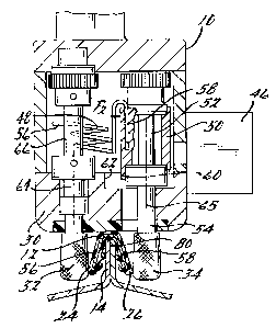
~ Figure 4 generally shows a preferred embodirnent of a roll crimping tooi ~() made ir.
- accordance with the teachings of the present invention. As shown, crimping tool 10 has a ~cdy
. 30 supporting a first roller 32 and a second roller 34. Rollers 32 and 34 are used s~- 3pp~y a
- compressive force on the leg poltions 24 and 26 of flange cover 12 when rollel s 32 and 34 are
activated and are in a closed position (shown in Fig. 7). The body 30 further provides for
attachment to a drive means 36. Drive means 36 may be attached directly to body 30 if it is of
appropriate size and weight for the operator to handle conveniently.
Alternately, as shown in Figure 5, a handle 38 may be utilized in conjunction with body
30, and a remote drive means 37 may be used. A flexible shaft 40, or other appropriate means,
is then required between remote drive means 37 and tool 10 to transfer the driving force from
remote drive means 37 to tool 10.
CA 02211611 1997-07-2~
Referring now to Figures 4 and 5, the body 30 further includes a contact surface 42 which
is placed in contact with flange cover 12 when tool 10 is being used by an operator. The contact
surface 42 may be made ofthe same material as the remainder of body 30 and includes at least
that portion of body 30 which is located between the first roller 32 and the second roller 34.
5 Alternately, a surface insert 44 can be added, as shown in Figure 5. Surface insert 44 is a
removable piece that can be replaced as tool 10 is used and the contact surface 42 experiences
wear. Surface insert 44 may be made of the same material as body 30, or may be made of a
di~re~ material, such as nylon or polytetrafluorethylene, which will reduce any friction between
the flange cover 12 and the tool 10 as it advances around the periphery of operling 16. By
10 utilizing a material which reduces friction and improves the interface between flange cover i 2 and
tool 10 any damage which may have otherwisc occurred to i~lange cover 12 cail be reduced or
eliminated.
With reference now to Figures 4, 6, and 7 it is shown that first rvller 32 and second roller
34 each extend beyond the body 30 oftool lG. T he first roiler 32 is fixed in its position while the
15 second roller 34 ~eely floats relative to the fixed position of the first rcller 32. The free fioating
position of the second roller 34 is determined by the coordination of a first biasing means 46 and
a second biasing means 48 acting in opposition to one another, the variation in thickness of flange
14, and any variation in flange cover 12 itself
The first biasing means 46 is utilized to urge the first roller 32 and the second roller 34 to
20 a closed position (shown in Figure 7) in which the distance between first and second rollers, 32
and 34 respectively, is reduced. This is accomplished by the first biasing means 46 acting on a
movable block 50 which supports movable shaft 52. Free floating second roller 34 is attached to
a first end 54 of movable shaft 52. First biasing means 46 includes any variable position biasing
CA 02211611 1997-07-2~
device, such as, but not limited to, an air cylinder, or electrical positioning device, which will
apply a generally consistent force (indicated in Fig. 7 by the arrow Fl) through substantially the
full range of motion of the free floating second roller 34.
The second biasing means 48 operates to urge the first roller 32 and the second roller 34
S to an open position (shown in Figure 6) in which the distance between first and second roll~rs 32
~ and 34 respectively, is increased. In the preferred embodiment shown, this is accomplished by a
first end 56 of the second biasing means 48 being held in a fixed position relative to the fi~.ed
position first roller 32, and a second end 58 of the second biasing means 48 attached to ancE acting
on movable block 50 which supports the shaft 52 to which the free floating second roller 34 is
10 . attached. The second biasing means 48 ma.y include a compression spring, a ~ension sp-ing, ~
torsional spring (as showr.), or any other biasing device which gives a generaliy constant force
(indicated in Figure 6 by the arrow F2) through substantially the full range of rnotion of the free
floating second roller 34.
When the crimping tool 10 is i.n a non-activated or deactivated state (fo! exampls when
15 no air pressure or electrical power is supplied to the first biasing means 46) the force F2 of secoi:ld
biasing means 4~ overcomes force F, of first biasing means 46 thereby urging the secGnd roller
34 to an open position as shown in Figure 6. This open position allows an operator to easily
position the tool 10 over the fiange cover 12, placing first roller 32 on a first side 56 of flange
cover 12, and second roller 34 on the opposite side 58 of flange cover 12, without forcing the leg
portions 24 and 26 to a closed position. When, for example, air pressure or electrical power is
supplied to first biasing means 46, the tool 10 is in an activated state (shown in Figure 7) and first
biasing means 46iS energized. When energized first biasing means 46 provides a consistent force
Fl to the free floating second roller 34 by way of movable block 50. Force F, is greater than the
CA 02211611 1997-07-2~
force F2 of the second biasing means 48, thereby causing second roller 34 to close upon the flange
cover 12, and crimp the flange cover 12 onto flange 14 positioned between leg portions 24 and
26.
Depending upon the particular application, the closing force F, can be incrementally
5 varied. A first configuration is to set F, sufficiently high so that a stop portion 60 of moveable
block 50 comes in contact with or "bottoms out" on a stop surface 62 of body 30. rhis is
considered to be a full closed position. This configuration has the advantage of providing a
generally kno~vn distance between the axes 64 and 65 of fixed shaft 66 and moveable shaft 52,
respectively. The radius of first roller 32 and secvnd roller 34 can be selected to provide the
10 applopli~te or desired spacing which will properly crimp flange cover 1 2. At the same time the
above describe~ configuration provides an open position when first biasing means 46 is in the non~
activated state allowing for easy positioning oftool 10 over flange cover 12 in its open condition.
Stop poltion 60 or stop surface 62 may have an adjustment to set the final spacing behh-een first
roller 32 and second roller 34.
A sec~nd configuration provides for setting the closing force Fl at a specific setting (less
than that ofthe first configuration). Closing force Fl urges the second roller 34 toward first roller
32 until the combined force ofthe second biasing means 48 (F2) and the outward directed reaction
force (FR) resulting from compressing flange cover 12, equal closing force Fl. (i.e. F2 + FR = Fl)
This provides an equilibrium in which the reaction force FR~ which is the force compressing and
crimping flange cover 12,is a known, consistent force since F, and F, are known and generally
consistent throughout the range of motion of free floating roller 34. The second configuration
still has the advantage of an open position when first biasing means 46 is in the non-activated state
allowing for easy positioning of tool 10 over flange cover 12 in its open condition. Further, the
CA 02211611 1997-07-2~
second configuration allows for applying a known generally consistent crimping force (equal to
and opposite from reaction force FR) instead of a particular fixed distance between first roller 32
and second roller 34. A consistent force is applied to crimp flange cover 12 regardless of the
thicknesses of flange 14 that occur around the periphery of opening 16 (shown in Figure 1).
5 Further, the distance between axis 64 and axis 65 can vary to accommodate variations in flange
14 or flange Gover 12, or both, while still providing a generally consistent force for crimping
flange cover 12.
Generally coincident with the activation of first biasing means 46 is the activation of the
drive means 36, or remote drive means 37 as the case may be. This provides rotational dri~,-ing
force to both first roller 32 and sesond roller 34. The drive means 36 or rernote drive means 37,
may be powered by an electric motor, by compressed air, or by any other suitable me3ns The
fixed position first roller 32 and the free floating second roller 34 are driven in opposite directions
and at generally ~he same rotativnal speed. The tool moves in a forward direction (Ar, ow D in
Figure 1) when contact is made witll first side 56 and opposite side 58 ofthe flange cover 12.
15 The theoretical linear speed of tool 10 is generally equal to the revolutions per minute of shaf~ 66
or 52 multiplied by the circumference of roller 32 or 34 as shown in the equation:
Linear Speed = RPM x 21lr.
The drive means, 36 or 37, incorporates a power bypass (not shown), such as a clutching
mechanism or a bleed off valve as appropriate for the type of drive means used. The power
20 bypass is adjusted such that as the combined frictional forces between the contact surface 42 and
flange cover 12, and the side loading forces on shafts 52 and 66 increase the power transferred
by the drive means, 36 or 37, to first roller 32 and second roller 34 is reduced. The combined
forces and the power bypass slow the linear speed of the tool 10 along the flange cover 12
CA 02211611 1997-07-2~
providing greater operator control along areas of the flange which require it. The frictional
portion of the forces increases due to first and second roller 32 and 34 being forced away from
one another when a thicker flange 14, or multiple flanges, are encountered. As first and second
roller 32 and 34 are forced further apart, a greater amount of contact surface 42 is brought in
contact with web 28 of flange cover 12, thereby creating a greater frictional resistance because
of the increased surface area contact. The side loading on shafts 52 and 66 will also typically
increase as a thicker flange or multiple flanges are encountered.
The profile 68 of first roller 32 and second roller 34 is specifically designed depending
upon the type of flange cover 12 which they are to be used with. Profile 68 is intended to
coordinate with each flange cover 12 such that after the flange cover 12 is crimped by first roller
32 and second roller 34, the core 22 is generally parallel to flange 14 and there is no palticula1.
area of leg portion 24 or 26 which is crimped tighter than any other area. 'rhe final position of
leg portions 24 and 26 are generally shown in Figure 3.
In addition to the profile 68 of first and second rollers 32 and 34 being coordinated with
each flange cover 12 it is intended to be used with, the surface 70 of rol]ers 32 and 34 may have
a gnarl pattern 72 or some other texture superimposed upon surface 70. This pattern 72 provides
sufficient friction between rollers 32 and 34 and flange cover 12 such that tool 10 will be pulled
in the direction of travel (arrow D in Fig I ) around opening 16 and will overcome the frictional
resistance between surface 42 and flange cover 12. Pattern 72 also prevents slipping of rollers
32 and 34 on flange cover 12 which could damage the surface appearance or degrade
performance of the flange cover.
A protective cap 74 may also be attached to or incorporated in a first end 76 of rollers 32
and 34. Cap 74 prevents the first end 76 of rollers 32 and 34 from contacting a body panel 78
CA 02211611 1997-07-2~
from which flange 14 is formed. Cap 74 is typically made of a non-abrasive, non-marring
material, such as teflon or nylon, which will not harm panel 78 or any finish which has been
applied to panel 78.
It is envisioned that a further alternate embodiment of a tool built according to the
5 teachings of the present invention could incorporate a third roller parallel to and offset from
contact surface 42, and positioned to contact the web 28 of flange cover 12 prior to the first and
second rollers 32 and 34 applying a crimping force. Alternately, the contact surface 42 could
incorporate a forrnation which partially encapsulates a ball bearing or a roller bearing such that
an exposed portion of the bearing is in contact with the flange cover prior to the first or second
10 roller applying a crimping force. Other low friction means or devices may also be incorporated
with the intent and purpose of applying an increased load upon the web 28 of flange cover 12
such that flange cover 12 is securely posit;oned again.st an end portion 80 of flange 14 prior to the
crimping force being appiied.
One skilled in the art will readily understand that the structure of the free floating secon(i
1 S roller can be incorporated in place of the first fixed roller, thereby providing a roll crimping tooi
having two free floating rollers. As shown in figure 5, the free floating first roller 82 and free
floating second roller 84 are allowed to travel within coordinated slots 85 and 86.
The foregoing discussion discloses and describes preferred embodiments of the present
invention. One skilled in the art will readily recognize from such discussion and from the
20 accompanying drawings and claims, that various changes, modifications, and variations can be
made therein without departing from the true spirit and fair scope of the invention.