Note: Descriptions are shown in the official language in which they were submitted.
- - -
CA 0221181~ 1997-07-29
FIELD OF THE INVENTION
This invention relates to a method and apparatus
for determining vehicle brake effectiveness and
changes in vehicle mass.
BACRGROUND OF THE INVENTION
In order for a driver to operate a vehicle
safely he must know and have confidence in the
stopping distance, and thereby the deceleration rate,
of the vehicle in all environments. Drivers learn to
judge this distance based on vehicle speed, road
slope, road surface and load conditions.
Two conditions that can alter the driver's
perception of a safe stopping distance are a non-
functioning or partially functioning brake system or
an unknown overload condition. As brakes do not wear
linearly and can be affected by temperature, brake
lining condition, moisture, adjustment, and mechanical
problems, stopping distance can change over a short
period. In addition, a vehicle may take on an
unexpectedly heavy load, thus affecting stopping
distance or vehicle deceleration rate.
Various systems for checking the effectiveness of
vehicle braking systems are known. Common methods
include visual inspection, mechanical devices (roller
testers, plate testers), brake pressure gauges, and
weigh scales to assure proper vehicle mass.
CA 0221181~ 1997-07-29
U.S. Patent S,299,452 (Caron et al.) determines
vehicle braking effectiveness by first measuring
engine torque to automatically calculate vehicle mass
and then employing a complex averaging method to
attempt to mitigate the effects of road slope, head
winds, tail winds and the like. The accuracy of
vehicle mass calculated by this method, using engine
torque, is dependant on constant engine horsepower,
transfer of horsepower to the wheels, fuel
consumption, altitude, road surface and a level
acceleration area. Changing vehicle conditions and
variations in normal driving conditions such as uneven
terrain, can significantly distort the calculation of
vehicle mass using this method. In addition,
estimating brake effectiveness based on level road
conditions does not account for travelling up or down
a slope. A brake effectiveness test that does not
take into consideration road slope does not offer the
real time feedback necessary to provide a true safety
application.
It would therefore be desirable to provide a
method and apparatus for providing feedback on vehicle
brake effectiveness for vehicles that do not
decelerate in the expected rate over a large spectrum
of environments.
It would further be desirable to provide a method
and apparatus of assessing vehicle brake effectiveness
which takes into consideration travelling up or down
a slope, differences in drag forces such as air
friction and engine friction and engine brake
engagement.
CA 0221181~ 1997-07-29
It would also be desirable to provide a method
and apparatus of assessing vehicle brake effectiveness
which includes a means of manually or automatically
inputting the actual mass of the vehicle for use in
calculating vehicle brake effectiveness.
It would further be desirable to provide a method
and apparatus of assessing vehicle brake effectiveness
based on a comparison with known vehicle deceleration
rates for a known vehicle mass at 100% braking
effectiveness.
It would also be desirable to provide a method
and apparatus of assessing vehicle brake effectiveness
based on a comparison with the minimum acceptable
deceleration rate for the vehicle.
It would also be desirable to provide a method
and apparatus of assessing vehicle brake effectiveness
~0 based on driver expected deceleration rates or on
vehicle braking effectiveness history. Data collected
on historical braking effectiveness can provide trends
which may be critical in assessing real time vehicle
safety and monitoring vehicle maintenance
requirements.
A further desirable object is to provide an
apparatus and method for alerting an operator to a
deterioration in braking effectiveness or to a mass
overload situation so that corrective action could be
taken before the problem becomes critical.
CA 022ll8l~ l997-07-29
It i8 also desirable that a method and apparatus
be provided which will permit easy access to stored
vehicle brake effectiveness data by certain authorized
government regulatory agencies for the purpose of
S accessing vehicle safety.
While other methods of assuring effective braking
for the main purpose of driver feedback and safety
have a certain degree of efficiency in certain
environments or braking areas, they do not provide the
advantages of the improved methods and apparatus of
the present invention as hereafter more fully
described.
SUM~IARY OF THE INVENTION
Determination of vehicle brake effectiveness is
accomplished by comparing predicted vehicle
deceleration rates and driver expected deceleration
rates, with actual measured vehicle deceleration.
Predicted and expected deceleration rates are adjusted
for variations in driving conditions such as slope and
drag.
If vehicle brake effectiveness is considered to
be 100%, relative gross vehicle weight (GVW) can also
be estimated by a comparison of predicted vehicle
deceleration rates with the actual measured vehicle
deceleration rate.
An input device, which may be an interactive
display/input device, allows the operator to input
load information manually, or automatically through a
CA 0221181~ 1997-07-29
radio frequency (RF) input interface or other standard
communication means connected to an automated weigh
scale. In this way, mass stored in memory provides an
accurate figure, which can always be assured. As mass
has a great impact on deceleration it is important
that this figure be accurate and consistent. A
minimum acceptable deceleration rate is also input and
fixed in memory for comparison to actual vehicle
deceleration rates.
For economic considerations it is desirable that
the device obtain data from various existing sensor6
which gather and use the data for other purposes.
This eliminates the need for the installation of
additional sensors and control devices. Most modern
tractor semi trailers are equipped with an electronic
control unit (ECU) which generates a signal
representative of vehicle wheel speed, distance, RPM,
gear ratio and brake system pressure. In some older
vehicles which do not have the necessary 6ensors or
ECU, it may be necessary to install sen60r6 and ECUs
to gather and process the required data.
Pressure transducers located throughout the
vehicle measure pressure applied to the brake air
chambers when the vehicle is being decelerated during
an application of its brakes. This data is sent to
the vehicle ECU via the automatic braking system (ABS)
and a signal representative of the brake system
pressure is generated. At the same time, or in the
alterhative~ a brake treadle pressure sensor may be
used to determine brake system pressure.
-
CA 0221181~ 1997-07-29
Road slope is calculated by comparing
measurements from a low-G accelerometer with wheel
based deceleration rates taken from the ABS. Slope
angle is used to adjust deceleration rates for a more
accurate comparison with actual and expected values.
In addition, the main ECU provides data on
vehicle speed, engine torque, engine RPM and engine
brake engagement (exhaust brake) which is used to
adjust deceleration for drag forces. Engine brake
engagement is monitored to assess the validity of any
results. If the engine brake is engaged, results are
invalidated and discarded.
Actual deceleration is compared to predicted
deceleration which has been adjusted for slope and
drag. Actual deceleration is also compared to driver
expected deceleration rates and a minimum acceptable
deceleration rate. Historic deceleration data stored
by the computer can be used to assess vehicle brake
effectiveness over time and determine maintenance
schedules or provide data for government safety
inspections. Comparisons are highly accurate due to
the various adjustments for slope and drag and the
accurate value for vehicle mass which has been
manually or automatically input. The computer
collects and stores data on vehicle brake
effectiveness over time for the purposes of historical
comparison, maintenance assessment and brake
inspection.
The invention provides feedback on vehicle
deceleration rate and signals a trend of degrading
- . -
CA 0221181~ 1997-07-29
brake effectiveness during vehicle deceleration.
Deviations from expected values could be the result of
brake problems, normal wear or an unknown vehicle mass
overload condition.
Results are automatically stored in memory for
future reference and historical brake effectiveness
compari60ns,~ and may be transferred via various
communications interferes to external devices for
other purposes such as maintenance control, government
monitoring or corporate data gathering.
It is therefore an object of the present
invention to provide an apparatus and method for
determining vehicle brake effectiveness.
It is a further object of the present invention
to provide a method and apparatus to give feedback on
vehicle brake effectiveness for vehicles that do not
decelerate in the expected rate over a large spectrum
of environments.
It is a still further object of the present
invention to provide a method and apparatus of
assessing vehicle brake effectiveness which takes into
consideration travelling up or down a slope,
differences in drag forces such as air friction and
engine friction and engine brake engagement.
It is also an object of the present invention to
provide a method and apparatus of assessing vehicle
brake effectiveness which includes a means of manually
or automatically inputting the actual mass of the
- - 7 -
CA 0221181~ 1997-07-29
vehicle for use in calculating vehicle brake
effectiveness.
It is a further object of the present invention
to provide a method and apparatus of assessing vehicle
brake effectiveness based on a comparison with known
vehicle deceleration rates for a known vehicle mass at
100% braking effectiveness.
It is an object of a preferred embodiment of the
present invention to provide a method and apparatus of
assessing vehicle brake effectiveness based on a
comparison with the minimum acceptable deceleration
rate for the vehicle.
It is another object of a preferred embodiment of
the present invention to provide a method and
apparatus of assessing vehicle brake effectiveness
based on a comparison with driver expected
deceleration rates or with vehicle braking
effectiveness history.
It is yet another object of a preferred
embodiment of the present invention to provide a
method and apparatus of determining a potential
vehicle mass overload condition that affects the
vehicle deceleration rate.
A further object of a preferred embodiment of the
present invention is to provide an apparatus and
method for alerting an operator to a deterioration in
braking effectiveness or to a mass overload problem 60
CA 0221181~ 1997-07-29
that corrective action can be taken before the problem
becomes critical.
It is also an object of a preferred embodiment of
the present invention to provide a method and
apparatus which will permit easy access to the stored
data on vehicle brake effectiveness for the purposes
of vehicle maintenance or for providing the data to
certain authorized government regulatory agencies for
the purpose of assessing vehicle safety or vehicle
load conditions.
According to the present invention then, there is
provided an apparatus for estimating the effectiveness
of a braking system in a wheeled vehicle, the
apparatus comprising: a means for inputting the mass
of said vehicle; a means for determining brake system
pressure during deceleration of said vehicle in a
normal operating mode; a means for determining road
slope; a means to determine air friction of said
vehicle and engine friction of said vehicle; a means
for determining predicted deceleration of said
vehicle; a means for determining actual deceleration
of said vehicle; a calculating means for calculating,
from data representing said actual deceleration, said
road slope, said air friction, said engine friction,
said brake system pressure and said mass, vehicle
brake effectiveness by comparing said actual
deceleration with said predicted deceleration for said
vehicle under comparable circumstances, and generating
a signal representative of said vehicle brake
effectiveness; and a means to record and store data.
CA 0221181~ 1997-07-29
~RIEF DESCRIPTION OF THE DRAWINGS
Preferred embodiments of the present invention
will now be described and will be better understood
when read in conjunction with the accompanying
drawings, in which:
Fig. 1 is a flow diagram illustrating the method
of the present invention;
Fig. 2 is block diagram illustrating the major
elements of the present invention;
Fig. 3 is a perspective view of a typical tractor
semi-trailer vehicle;
Fig. 4 is a schematic view of the brake control
system of the tractor as shown in Fig. 3.
20Fig. 5 is a schematic view of the brake control
system of semitrailer as shown in Fig. 3.
Fig. 6 is a schematic view of a free body
acceleration diagram showing the measurement of slope
angle.
Similar reference numerals are used in the
Figures to denote similar components.
- 10 -
CA 0221181~ 1997-07-29
DETAILED DESCRIPTION OF THE INVENTION
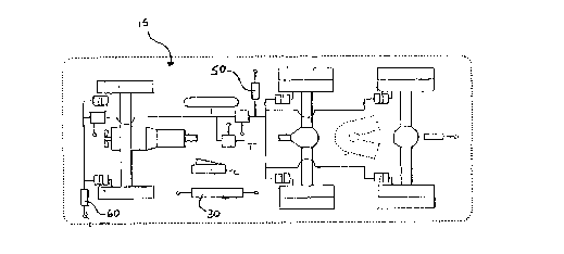
The apparatus for determining vehicle brake
effectiveness 100 is best understood by reference to
Figs. 2, 3, 4 and 5. Fig. 3 shows a typical tractor
semi-trailer vehicle 40 comprising a tractor 15 and a
trailer 20.
As shown in Figs. 4 and 5 tractor 15 and trailer
20 include a drive axle pressure transducer 50, a
steering axle pressure transducer 60, and a trailer
pressure transducer 70. These transducers monitor air
pressure delivered to the corresponding brake air
chambers and provide a signal to the automatic brake
system (ABS) 120. The signal provided to ABS 120 by
pressure transducers 50, 60 and 70 is representative
of overall brake system pressure and is used to
determine the predicted vehicle deceleration rate of
the vehicle as will be described below. At the same
time, or in the alternative, brake system pressure can
be determined by a brake treadle pressure sensor 130
(Fig. 2) on the brake treadle itself. Tractor 15
includes an electronic control unit (ECU) 30 connected
to ABS 120. ECU 30, ABS 120, pressure transducers 50,
2560, and 70 and brake treadle pressure sensor 130 are
standard equipment on most tractor semi-trailer
vehicles, however, vehicles not having such equipment
can be easily retrofitted.
30With re~erence now to Fig. 2, the apparatus for
determining vehicle brake effectiveness 100 also
includes a computer 110 comprising memory, a central
processing unit (CPU) and mass storage. Included in
- 11 -
CA 0221181~ 1997-07-29
the circuits of computer 110 are drag calculation
circuits 150 for calculating vehicle drag force and a
slope sensor 140 which includes a low-G accelerometer.
Computer 110 is connected to existing vehicle
automatic brake control system (ABS) 120 via existing
vehicle electronic control unit (ECU) 30. A means 160
for inputting actual vehicle mas6 (M) or maximum gross
vehicle weight is provided. Mass may be input
manually by the operator or entered automatically
directly from automated weigh scales. A further input
means 190 is provided to input driver expected
deceleration rate and minimum acceptable deceleration~
rate to computer 110.
The apparatus for determining vehicle brake
effectiveness 100 is provided with an output interface
170 including a data transfer circuit, communication
means and means for saving data to a storage device.
It will be clear to those skilled in the art that
output interface 170 may include various communication
means including a physical connector or an automatic
remote radio frequency (RF) output which can be used
to send and receive data without the need for the
vehicle to stop. Included as well is an indicating
device 180 which may include a video display terminal
(VDT), a series of lights or analog dials, or an audio
signalling means to provide output on vehicle brake
effectiveness and a warning of vehicle brake
deterioration to the vehicle operator.
Road slope sensor 140 produces a signal
representing road inclination angle ~ (Fig. 6). Road
610pe sensor 140 includes a low-G accelerometer to
CA 0221181~ 1997-07-29
measure vehicle acceleration. Circuits within
computer 110 compare vehicLe acceleration measured by
the low-G accelerometer to wheel based acceleration
measured by ABS 120 to calculate road slope angle ~.
With reference to the free body diagram shown in Fig.
6, inclination angle ~ is calculated using the
following formula:
~ = SIN-1 [[Af-Ax]/g];
where: ~ = inclination angle or slope;
Af = forward vehicle acceleration obtained
from a measurement of the change in
wheel based speed over time, calculated
by ABS lZ0 using the formula:
Af = dVf/dt
where Vf = wheel speed in the forward
. direction and t = time;
Ax = forward vehicle acceleration as
measured by the low-G accelerometer;
g = gravity (Constant)
The measurement of vehicle acceleration Af as
calculated by ABS 120 from the derivative of steering
wheel speed is an accurate measurement of vehicle
acceleration when the wheels are not slipping. It
will be appreciated that under most conditions,
CA 0221181~ 1997-07-29
steering wheels of tractor semi-trailers are not
capable of locking. Wheel based acceleration measured
in this way is unaffected by road slope.
By contrast, vehicle acceleration Ax measured by
the low-G accelerometer on the slope sensor 1~0 is
affected by slope angle. If the vehicle is travelling
on an upward 61Ope, as shown in Fig. 6, the force of
gravity (g) acting on the low-G accelerometer will
have two components; gy acting perpendicular to the
direction of travel of the vehicle will have no effect
on the acceleration rate measured by the low-G
accelerometer; and gx acting 180 degrees opposite to
the direction of travel of the vehicle will have a
negative effect on the acceleration rate measured by
the low-G accelerometer. Since wheel based
acceleration Af, as measured by ABS 120, is unaffected
by gravity, the difference between wheel based
acceleration Af and the acceleration measured by the
low-G accelerometer Ax is, by the above-noted formula,
an accurate measure of the angle of inclination ~ or
road slope.
If the vehicle is travelling on an downward slope
the force of gravity (g) acting on the low-G
accelerometer will again have two components; gy acting
perpendicular to the direction of travel of the
vehicle will have no effect on the acceleration
measured by the low-G accelerometer; and gx, this time
acting in the direction of travel of the vehicle, will
have a positive effect on the acceleration measured by
the low-G accelerometer. Again, since wheel based
acceleration, as measured by ABS 120, is unaffected by
CA 0221181~ 1997-07-29
gravity, the difference between wheel based
acceleration Af and acceleration measured by the low-G
accelerometer Ax is, according to the above-noted
formula, the angle of inclination ~ or road slope.
In another embodiment of the present invention
(not shown), a second low-G accelerometer i6 mounted
on the slope sensor circuit 140 and positioned to
provide readings for lateral acceleration during
cornering. Lateral acceleration readings are used to
warn the vehicle operator of a potential roll-over
condition during excessively sharp cornering.
Drag friction caused by air resistance and engine
friction is determined by drag calculation circuits
150 in computer 110. Drag calculation circuits 150
use vehicle speed, engine RPM, engine torque and
engine brake output as provided by ECU 30 and ABS 120
to calculate a figure for vehicle drag. Monitoring of
engine brake engagement is important since any
engagement of the engine brake will corrupt the test
results and prevent any meaningful comparison with
known standards. If the engine brake i6 engaged,
results are invalidated and discarded.
Actual vehicle mass is input to computer 110
manually by the operator or automatically from
automated road scales. Also included is a value for
the maximum legal gross vehicle weight (GVW) which is
the maximum load legally allowed for a particular
vehicle. The system will always calculate brake
effectiveness based on the maximum legal gross vehicle
- 15 -
CA 0221181~ 1997-07-29
weight figure, but will also calculate brake
effectiveness based on other mass values provided.
Operation of the apparatus for determining
vehicle brake effectiveness 100 is best understood by
reference to Figure 1. A driver expected deceleration
rate (DED) 200 is input by the operator via keyboard,
read/write identification tag or card or semi-
conductor chip. This rate i8 one which the operator,
may have obtained from the last vehicle driven and
represents a safe estimated deceleration rate against
which the operator wishes results compared. - Vehicle
mass ~M) 20~ is input manually by the operator or
automatically by automated weigh scales. A figure for
maximum legal GVW may also be input at this time or
can be stored permanently by computer 110. Brake
pressure is applied 204, and brake system pressure
(SP) 206 is determined, from a measurement of brake
treadle pressure and/or brake air chamber pressures,
during a deceleration procedure. All measurements of
air chamber pressures from transducers 40, 50 and 60
are sampled every 1/100 second and averaged for the
test period which may range from a minimum .3 seconds
to a maximum 3 seconds. At the same time, or in the
alternative, brake system pressure is determined by
brake treadle pressure sensor 130. Road slope angle
~ is calculated 208 and drag force (R) is determined
210. It should be noted that road slope angle ~ and
drag force (R) are monitored continuously by computer
110 so that figures are immediately available when
required. A figure for vehicle wheel based
deceleration (Af) 212 is obtained from ABS 120 and a
figure for actual vehicle deceleration (AD) is
- 16 -
CA 0221181~ 1997-07-29
obtained from the low-G accelerometer on the slope
sensor 140.
Predicted deceleration (PD) 216 is calculated by
a comparison of measured brake system pressure (SP)
with a table of known deceleration data stored by
computer 110 obtained from tests at 100~ brake
effectiveness. Predicted deceleration (PD) i8
adjusted for slope 218 and for drag 220. Actual
vehicle deceleration rate (AD) is compared to the
adjusted value of predicted vehicle deceleration ~NPD)
222 to provide a figure for vehicle brake
effectiveness (BE) compared to known values. Actual
vehicle deceleration (AD) is also compared to the
vehicle minimum acceptable deceleration rate (MD) 224,
adjusted driver expected deceleration (NDED) 226, and
historical stored values (HD) 228. Output 230 is
provided to an indicating device 180 (Fig. 2) to
provide a means of warning the operator of potential
brake problems or a mass overload condition, or for a
comparison with historical braking effectiveness data.
Output 230 is also sent to a storage device connected
to computer 110 for use in future historical
comparisons of brake effectiveness data. Output 230
can be in the form of a visual display or an audible
signal or both. Output 230 is also provided to an
output interface 170 (Fig. 2) which is used to
communicate data from the invention to remote devices
for monitoring of brake maintenance or to provide data
on brake effectiveness to government regulatory
agencies.
CA 0221181~ 1997-07-29
To determine a potential mass overload situation,
the operator compares the reading for vehicle brake
effectiveness taken immediately before loading to a
reading for vehicle brake effectiveness obtained
immediately after loading. Any significant difference
between the two readings would be due to either a mass
overload situation or faulty brakes. To confirm the
cause, the operator could weigh the load or di~connect
the load and perform another brake effectiveness test.
If brake effectiveness returns to the reading prior to
loading, a mass overload would be confirmed. If not,
a brake problem would be indicated. Alternatively, if
the operator does not have any immediate prior
readings for vehicle brake effectiveness, a comparison
can be made with stored test data for unloaded and
maximum load conditions which were obtained at 100%
vehicle brake effectiveness. Any significant
differences would indicate a mass overload situation
or a brake problem.
As noted, the apparatus for determining vehicle
brake effectiveness lOO can assess vehicle brake
effectiveness by any one of four different methods:
a5 1) compare actual vehicle deceleration (AD) with
adjusted predicted vehicle deceleration rate (NPD) for
the same mass at 100% brake effectiveness 222;
2) compare actual vehicle deceleration (AD) with
a minimum acceptable vehicle deceleration rate (MD)
a24;
- 18 -
CA 0221181~ 1997-07-29
3) compare actual vehicle deceleration (AD) with
a driver expected vehicle deceleration rate (DED)
entered by the operator via keyboard, read/write
identification tag or card or semi-conductor chip 226;
and
4) compare actual vehicle deceleration (AD) with
historical data of deceleration rates (HD) for that
particular vehicle 228.
In accordance with method number one, in order to
compare actual vehicle deceleration (AD) with known
vehicle deceleration rates at different vehicle masses
and brake system pressures, computer 110 is provided
with storage for a table of test data representing
deceleration rates for the current vehicle in which
brake effectiveness is known to be 100%. At 100%
brake effectiveness, braking force has a constant
relationship with brake system pressure.
Test data is obtained by decelerating test
vehicles on a flat surface using various brake system
pressures (SP). Deceleration rates are measured with
an accelerometer. This produces a brake system
pre6sure versus deceleration rate curve for a given
vehicle mass. Net braking force (F) is derived by the
formula:
F = SP x k = M x D
where M = actual vehicle mass, D = deceleration rate
and k represents the constant relationship between
brake system pressure and force. The re6ults are
- 19 -
CA 0221181~ 1997-07-29
( '
stored as a table by computer 110. It should be
obvious to one skilled in the art that a computerized
algorithm or graph stored in computer 110 could
perform the same function as the above-described
table.
Once actual brakè system pressure (SP) has been
measured during an actual vehicle braking procedure,
computer 110 locates the same brake system pressure in
its table of stored test data and determines the
predicted vehicle deceleration (PD) by the formula:
PD = F / M
The result is a predicted deceleration rate (PD) which
is then adjusted for road slope using the following
formula and the slope angle calculation described
above, to give a slope adjusted predicted deceleration
rate ( SPD ):
SPD = PD - [ g x sin ~]
Variation in drag force (R), such as that caused
by air resistance and engine friction have a very
limited effect on deceleration rates in most vehicles.
Nevertheless, these forces can be estimated by
monitoring vehicle speed, engine RPM and engine
torque. Net predicted deceleration is calculated by
the following formula:
NPD = SPD - [R / M]
- 20 -
CA 0221181~ 1997-07-29
Vehicle brake effectiveness (BE) is calculated as
follows:
BE = AD / NPD
where AD is actual vehicle deceleration as measured by
the low-G accelerometer. The result can be shown as
a percentage or represented by a graph and an audible
or visual warning can be sent to the vehicle operator
to warn of a brake effectiveness reading outside a
particular pre-determined range.
In accordance with method number two, the minimum
acceptable vehicle deceleration rate (MD), which is
independent of current vehicle mass, road slope or
drag force, is determined. MD represents the minimum
rate at which the vehicle must stop, regardless of the
mass. Vehicle brake effectiveness compared to minimum
acceptable vehicle deceleration is calculated by the
formula:
BE = AD / MD
and is displayed as a percentage or represented on a
graph. Again, an audible or visual warning can be
sent to the vehicle operator to warn of a brake
effectiveness reading less than the accepted minimum.
This will signal a serious problem with the vehicle
brakes or a mass overload situation.
In accordance with method number three, driver
expected deceleration rate (DED), entered manually by
- 21 -
CA 0221181~ 1997-07-29
the operator, is adjusted for slope and drag using the
following formula:
NDED = DED - [g x sin ~] - [R / M]
to arrive at net adjusted driver expected deceleration
(NDED). Vehicle brake effectivene6s compared to net
adjusted driver expected effectiveness is:
BE = AD / NDED
This result is displayed as a percentage or
represented on a graph and warnings are given to the
15 operator should the brake effectiveness be less than
expected by the operator.
In accordance with method number four, computer
110 compiles and stores historic data of actual
vehicle decelerations (HD), recording actual
deceleration rate, brake system pressure, slope,
drag force, vehicle mass and date. This data is
stored in the same type of table used to store known
deceleration rates used in method number one
described above.
Historic data is compared to the current data
from a current vehicle deceleration to assess
vehicle brake effectiveness. Current data can be
compared to data from any previous deceleration or
to an average of data for all previous
decelerations. This comparison provides the
operator with a means of asses6ing current brake
- 22 -
CA 0221181~ 1997-07-29
('''
performance based on historical brake performance
for that vehicle.
Historic data can also be used to determine a
brake maintenance schedule or can be sent to remote
devices for monitoring brake effectiveness or to
provide data on brake effectiveness to government
regulatory agencies.
A preferred embodiment of the invention has
been described, however, numerous modification,
variations and adaptations, obvious to one skilled
in the art, may be made to the particular embodiment
of the invention described above without departing
from the spirit and scope of the invention as
defined in the claims.